
Chapter 8
Build a Motorized Wooden Platform
You read in the preceding chapter how to use wood to create robots. In this chapter you can put that knowledge to good use to build the PlyBot, a simple, affordable, and expandable robot base using just a small sheet of 1/4″ plywood. Only simple straight cuts are used. You need to drill just six holes to mount the two motors and the ball caster.
The construction of the PlyBot requires no special tools. You need a saw for cutting the wood and a drill for making holes. Plus: a screwdriver and small pliers for assembling the pieces. Parts for the PlyBot are available online and at better-stocked hobby stores.

In the text that follows I provide the exact model numbers for the pieces you need. But remember that you’re free to substitute with something else if you already have it or if you’ve found substitutes that are cheaper or easier to get. See also the RBB Online Support site (check out Appendix A) for additional parts sources and alternatives.
Making the Base
Refer to Table 8-1 for a list of parts.
Figure 8-1 shows the completed PlyBot, with wooden base, twin gear motors, wheels, and support caster. The robot measures 5″ × 7″ overall. The base is constructed from 1/4″-thick 5-ply birch plywood and is driven by two Tamiya worm gear motors; the motors come in kit form, and assembly takes 10 to 15 minutes for each motor. The wheels, also made by Tamiya, securely lock onto the axles of the motors using hardware that’s included.
The “third wheel” of the PlyBot is a ball caster—more technically called a ball transfer, as they are used on conveyor belts to literally transfer goods (boxes, palettes, machinery) throughout a warehouse or factory. I used a ball caster/transfer from McMaster-Carr (www.mcmaster.com), a large and well-known online industrial supply retailer. The caster costs under $5, and you can substitute another for it if you like, as long as it’s about the same size. Your caster should have a flange-to-ball depth of about 1″ to 1.5″.

CUTTING AND DRILLING
Begin construction by cutting the wood to 5″ × 7″. Then, using Figure 8-2 as a guide, cut the sides of the wood to create a narrowing shape. The finished base should look like Figure 8-3.
Once the base is cut, use a sander or small rasp to round off the four corners. This is not mandatory, but it makes for a nicer overall shape and appearance. You should also apply a light sanding to the base now, to remove any rough edges caused by cutting. If you wish, you may apply a coat of sealant or varnish to close the pores of the wood. This will prevent it from absorbing moisture, which could cause warping.
Consult the drilling template in Figure 8-4. Use a 1/8″ drill bit for all holes. The location of the holes are not supercritical except for the distance between the two holes for each of the motors. These need to be fairly accurate, though take note that the holes in the mounting flanges of the Tamiya gear motor are oblong. This allows a few millimeters’ leeway in matching the motors to their mounting holes.
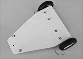
Figure 8-1 The PlyBot uses two Tamiya gear motors and wheels, plus a ball caster (or skid) for balance. It’s made using a single piece of quarter-inch-thick 7″ × 5″ aircraft plywood.
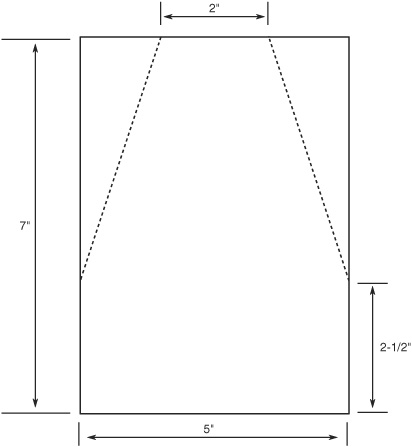
Figure 8-2 Cutting guide for the PlyBot. Dimensions are flexible, and you can scale the robot up in size if you need something a bit bigger.
Before assembly of the motors, use the motor flange itself to mark the spacing on a piece of paper. You can then transfer the marks to the wooden base using a small punch or a nail.

Figure 8-3 Plywood panel cut to shape for the PlyBot. Use a sander or small rasp to round off the corners for a sleeker look.
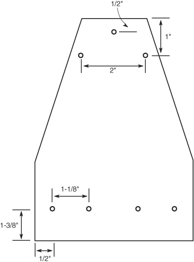
Figure 8-4 Drilling template for the PlyBot. The extra hole at the top is for the optional skid, should you wish to not use a ball caster. Turn the robot over so the clearance between the ground and the base is reduced.
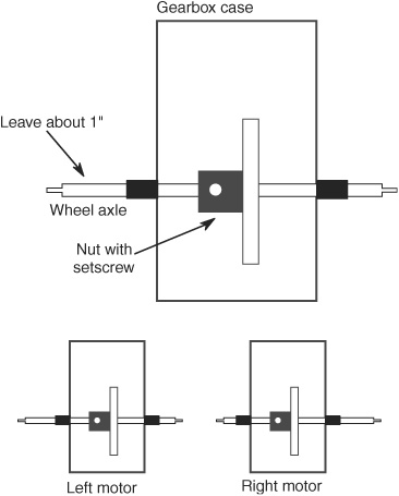
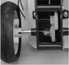
Figure 8-5 Tamiya worm gear motors, showing the alignment of the wheel axle through the output gear. Leave about an inch of the axle showing for mounting the wheel. Make a “left” and a “right” motor, as shown.
Building and Attaching the Motors
The PlyBot uses two Tamiya #72004 worm gear motors. They’re called worm gear because of the type of gearing mechanism that’s used. Even though the gearbox of the motor uses just three gears, it has a high gear reduction, meaning the wheels turn fairly slowly—about the right speed for a small bot.
While assembling the motor you may select either of two ratios: 216:1 or 336:1. I built the prototype PlyBot using the lower, 216:1, ratio, so that the robot scooted around the floor a bit faster. You can opt for either ratio, but make sure both motors are assembled the same way, or your PlyBot will run around in circles! Assembly instructions are included with the motor. You’ll need a small Philips-head screwdriver and pair of needle-nose pliers to build it.
The motor comes with two long wheel axles. You want the axle with the holes drilled into each end. You can save the other axle for some other project.
The axle is secured to the gearbox gears using a set screw. Initially position the axle so that about 1″ sticks out of the side of the motor (see Figure 8-5). You’ll be adjusting the position of the axle after you’ve mounted the motors, so for now just lightly tighten the set screw.
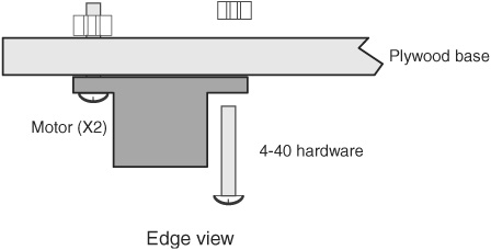
Figure 8-6 Mounting the motors using 4-40 hardware fasteners.
You’ll be building one left motor and one right motor. That means the 1″ of axle should point to the left on one of the motors and to the right on the other.
Important! Prior to inserting the motor into the gearbox, manually rotate the gears so that the set screw on the wheel axle points upward (away from the mounting flanges). This allows you to fine-tune the position of the axle once the motors have been mounted. If you don’t do this now, you might not be able to access the set screw.
Attach each motor to the underside of the plywood base, as shown in Figure 8-6. Use two 4-40 × 1/2″ machine screws and nuts. Feed the screws from the motor side, and tighten the nuts on the top of the base. You may use #4 washers (if you choose) on the nut side.
Building and Mounting the Wheels
The Tamiya wheels specified in the parts list are designed to directly attach to the axle of the worm gear motor. The wheels are in kit form and come with two different hubs. You want the hubs for the 4mm round axles, the kind used in the worm gear motor. These hubs are visually identified with a thin slot that runs through the center. Assemble the wheels according to the instructions that come with the set.
Before mounting the wheels, use a pair of pliers to insert the small spring pin (included with the motor) into the hole at the outside (wheel) end of the axle. The pin engages into the slot in the wheel hub. Without the pin, the wheel will just freely rotate over the axle.
The wheel securely mounts to the axle using the supplied nut. The Narrow Tire wheel set comes with a small plastic wrench for use in tightening this nut over the axle. The wheel set only comes with two nuts, so don’t lose these! They can be hard to replace because of their small size.
Attaching the Ball Caster
The ball caster attaches to the front of the robot using two 4-40 × 1/2″ screws and nuts. The screws should be inserted from the top side of the base; tighten the nuts against the mounting flange of the ball caster. Figure 8-7 shows the 4-40 hardware used with the ball caster, and Figure 8-8 shows the caster attached to the bottom of the PlyBot base.

Figure 8-7 Mounting the ball caster using 4-40 hardware fasteners.
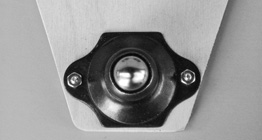
Figure 8-8 Ball caster (a.k.a. ball transfer) as specified in Table 8-1. You can substitute any other caster mechanism that is the same approximate size.
The PlyBot is “invertible,” meaning you can turn it over, and the side with the motors becomes the top of the bot. If you do this, there’s isn’t enough clearance for a ball caster. Instead, construct a skid using an 8-32 × 3/4″ machine screw and matching 8-32 hex nut and acorn (cap) nut. The acorn nut provides a smooth surface for the skid to glide against. You can adjust the height of the skid using the hex nut.
Drill a hole just smaller than the diameter of the screw, so that the screw makes it own threads when you insert it. Be careful not to make the hole too small, or else the wood may chip as the screw is tightened.
Using the PlyBot
The Tamiya motors used in the PlyBot are rated for 3 to 6 volts. You can rig them up to switches to manually control the motor (on/off and direction) or use electronic control. These topics are covered in Chapter 22, “Using DC Motors,” as well as the My First Robot lessons found on the RBB Support Site.
![]()
We’re getting a bit ahead of ourselves here, but this needs to be mentioned now: When run at 4.5 volts, the motors draw less than 100 milliamps of current. But if the motors stall—meaning they are physically stopped while voltage is still applied to them—current consumption goes up to about 1.5 amps.
Bear this in mind when using electronic control of the motors. Be sure the drive electronics can handle the current. See Chapters 21 and 22 for more details on current consumption of motors and what it means.
The PlyBot has plenty of room on top (and underneath, too) for mounting electronics, batteries, sensors, and other paraphernalia. Because the base is made of wood, it’s easy to drill additional holes for mounting components.
Variations on a Theme
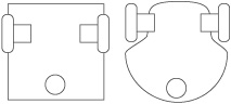
The PlyBot is the basic “T-bone” robot, where there’s a pair of two motors on one end of the bot and a supporting caster or skid on the other. Figure 8-9 shows the concept, whereby you can readily visualize the “T” shape of the bot.

Figure 8-9 Concept of the “T- bone”-shaped robot, where—like the PlyBot—the wheels are located on one end of the base, and a balancing caster or skid at the other.
An advantage of this style of robot is that it’s easy to construct using common materials. The motors attach to the top of the “T,” and the caster or skid to the opposite end. As shown in later chapters (see, for example, Chapter 14, “Rapid Prototyping Methods”), you can often find materials that are already in this shape. Just stick on the caster and the two motors and wheels, and you’ve made yourself a robot.
The exact shape of the base is not relevant to the function of the robot, though for best results smooth or round contours work best. The corners of square robots can snag on furniture and other objects. Though it’s a bit more work, smoothing out the shape of the base provides a more streamlined look, and it allows the robot to navigate more easily, and with less potential damage to its surroundings.