
Chapter 32
Using Solderless Breadboards
Solderless breadboards let you experiment with circuits without having to solder together components. You literally plug in the parts and string some wires to complete the connections. You save time, and you get to play with your creation that much sooner.
And, just as important, you can easily change the value of components to see if another one works better. Just unplug the old, and switch in the new.
While solderless breadboards are intended for experimentation and testing, there’s no law that says you must eventually solder your circuit together to make it permanent. Many robot builders construct the solderless version only and use it that way for weeks, months, even years.
But, of course, you always have the option of someday transforming your brightest sans solder ideas into gleaming soldered-together circuits. In this chapter you’ll learn how to best leverage solderless breadboards in your robotics projects. The next chapter is devoted to making circuit boards using soldering and other more permanent electronics construction techniques.
Anatomy of a Solderless Breadboard
A solderless breadboard (see Figure 32-1) is made of plastic and is composed of many columns and rows. The columns are wired inside the board so that anything attached to that column shares a single electrical connection (see Figure 32-2). To use the board, you start by plugging in ICs, resistors, and other components. You then establish how they’re interconnected by stringing wires from one column to another.
SIZES AND LAYOUTS
All solderless breadboards consist of holes with shared internal contacts. These contacts are spaced one-tenth of an inch apart—just right for integrated circuits, most transistors, and discrete components like capacitors and resistors. The holes, called contact points or tie points, are the proper size for 22-gauge solid conductor wire. On each column you can connect together as many as five wires or components.

Figure 32-1 Solderless breadboard with 400 tie points.
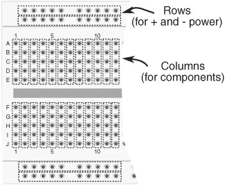
Figure 32-2 Underneath the holes in the breadboard are strips of conductive metal with spring contacts. Plugging a wire into a hole pushes the wire into the contacts.
In addition to the column connections, many solderless breadboards have long rows on the top and bottom. These provide common tie points for the positive and negative power supply.
But from here, the size and layout of breadboards can differ greatly. Some measure a few inches square and contain only 170 holes. The 170-tie-point boards are made for simple circuits with one or two small ICs or a handful of small components. For bigger circuits you need a bigger breadboard. You can pick among models with 400, 800, 1200, even 3200 tie points.
Which size should you get? I believe in starting out small, the extra benefit being that small breadboards cost less. They’re usually more than adequate for testing the typical robot control or sensor circuit. You can always get a larger board as your needs grow.
MAKING CONTACT
The contact points are usually made from a springy metal coated with nickel plating. The plating prevents the contacts from oxidizing, and the springiness of the metal allows you to use different-diameter wires and component leads without seriously deforming the contacts. However, the contacts can be damaged if you attempt to use wire that’s larger than 20 gauge. (Remember: Wire gets bigger with smaller gauges.)

The more you use your solderless breadboard, the faster it’ll wear out. After a while, the springy metal isn’t so springy. Dust can settle inside the contact points and decrease the electrical contact. This is another reason not to invest in a large and expensive breadboard. The cheap ones don’t cost as much when they need to be replaced.
Things you should not try to plug into a solderless breadboard contact point include:
Stranded conductor wire, which won’t work reliably, even if you twist the strands.
Larger than 20-gauge wire or fat component leads.
Smaller than 26-gauge wire or really skinny component leads (the electrical contact will be iffy, at best).
High-voltage sources of any kind—these include wires from an AC wall socket or any circuit that uses high voltage. Solderless breadboards are for low-voltage DC circuits only.
CONNECTING WIRES FOR YOUR BREADBOARD
No solderless breadboard is complete without wires, but you can’t use just any wire. The best wire for solderless breadboards is:
![]() 22-gauge
22-gauge
![]() Solid conductor
Solid conductor
![]() Plastic insulated
Plastic insulated
You want wires of different lengths, with about 1/2″ of the insulation stripped off each end. These jumper wires are available premade, or you can make them yourself. I prefer the pre-made kind.
If you decide to make your own set of breadboard wires, look for wire spool assortments with different colors. For starters, cut the wires into the following lengths:
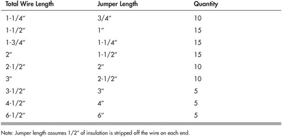
1. Start by cutting the wires to the total wire length, as indicated.
2. Use a pair of wire strippers to remove 1/2″ of insulation off each end, as shown in Figure 32-3. While stripping the insulation, insert one end of the wire into the stripping tool (if it’s adjustable, dial it for 22-gauge) and hold the other end with a pair of needle-nose pliers—the kind without serrated jaws is the best.
3. After stripping the insulation, use your needle-nose pliers to bend the exposed ends of the wire at 90°, as shown.
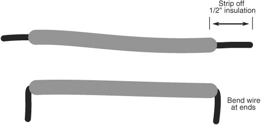
Figure 32-3 To make your own breadboard jumpers begin by stripping of 1/2″ of insulation from both ends, being careful not to nick the wire (that weakens it and can cause the wire to break off easily). Finish by bending the wires at the ends.
USING PIN JUMPERS
Solid conductor wire can break when it’s used too much. Due to metal fatigue, the wire just snaps off—sometimes right inside the breadboard contact point (use a small needle-nose pliers to remove these).
For longer-lasting wires, you want to purchase or make a set of jumpers made with stranded conductor wire, with soldered-on machine pin ends. These last much longer than regular solid conductor jumpers, though they’re a lot more expensive if you buy them ready-made.
![]()
Check out the RBB Online Support site for a step-by-step pictorial on making your own pin jumpers. See Appendix A for more details about the support site.
MAKING PIN HEADERS FOR OFF-BOARD COMPONENTS
There are times when you want to use components—speakers, switches, potentiometers—that just won’t fit into the holes of the breadboard. You can make pin jumpers for these, too. But instead of soldering a pin to each end of the wire, you solder a pin to one end, and on the other end you connect to the component. Figure 32-4 shows the general idea.
For components that you don’t want to permanently solder to, use just a single header pin and an alligator or pushpin jumper wire. The pushpin type is smaller and wraps around the small-diameter pin a little better. Then connect the other end of the jumper to the component.
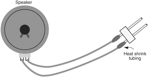
Figure 32-4 Example of a pin header permanently soldered to a component (a speaker shown here) that cannot by itself plug into the breadboard.
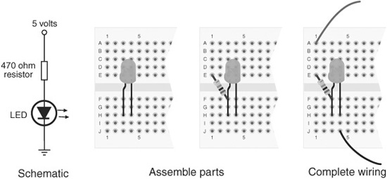
Figure 32-5 Steps for assembling a solderless breadboard circuit from a schematic. Start with the largest components, and insert them into the breadboard. Add smaller components, then attach connecting wires.
Steps in Constructing a Solderless Breadboard Circuit
Building a solderless breadboard project is merely a matter of placing the electronic components into the tie points and then completing the circuit using jumper wires. Start with a schematic or other plan, as shown in Figure 32-5.
1. Identify the components of the circuit and collect them before you begin. There’s nothing worse than starting to build a circuit, only to discover you’re missing some important part.
2. Visualize the best placement for the components. On simple circuits this is easy to do, as you’ll have plenty of room. On more complex projects you’ll want to carefully plan the best spot for each part, so that everything will fit.
3. Place the parts into the tie points of the breadboard starting from one end of the schematic and proceeding to the other. For the example circuit, the “ends” are the + and − power leads, but on others it could be a signal input or a sensor output. I’ve elected to start with the LED, as it’s the largest of the components.
4. Finish the construction by adding any jumper wires that are needed, including the power leads.
Though the breadboard is constructed with columns and rows at right angles, there’s no rule that says you must place parts in such rigid rank-and-file order. Feel free to turn parts this way and that, to take best advantage of the tie points.
Making Long-Lasting Solderless Circuits
Of course, you already know solderless breadboards are not “intended” for permanent circuits. But if your aim is to build a circuit on a solderless breadboard and keep it that way, you’ll want to ensure a solid construction. Bird’s-nest wiring and loose components just won’t cut it.
Use a new board, one where the spring contacts aren’t already getting loose. The low price of a small breadboard means you can keep a stock of these and use them as needed.
Firmly seat all components, including resistors, capacitors, and diodes. This means you need to trim the lead lengths so that the body of the component sits flush with the surface of the board.
Cut jumpers to length, and carefully route them around components and other jumpers so that none will accidentally pull out. Push the jumpers flush against the board.
To help prevent parts and wires from coming loose, strap them in using some rubber bands. Avoid the use of things like cling plastic wrap for storing food. This generates lots of static electricity when you apply and remove it, possibly ruining your circuit.
Mounting the Breadboard to Your Robot
If you’re using the breadboard directly on your robot, you’ll want to securely mount it to keep it in place. Otherwise it may fall off the next time your bot does a pirouette turn, and all your hard work will be ruined as parts scatter onto the floor.
If the breadboard is readily accessible—so you can work on it—you can simply use double-sided foam tape to secure it to the robot (see Figure 32-6). Otherwise, use Velcro or other hook-and-loop material, so you can peel the board off to work on it.
When double-sided tape and Velcro won’t work, use long cable ties to hold the board in place. Use two wraps, one at each end. Cinch the tie for a secure fit. If you need to later remove the board (so you can work on it on your bench), just cut the ties and discard. Use new cable ties when you’re ready to remount the board on your robot.
Some breadboards, such as the Global Specialties EXP-350, have mounting holes in the corners. The holes are usually pretty small, so you need 4-40 or maybe 2-56 miniature screws and nuts. The EXP-350 accepts 4-40 machine screws and nuts; use flathead screws for a flush look. Or it accepts 6-32 screws from the back, which tap straight into the plastic.
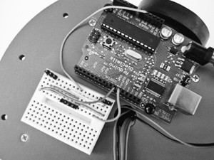
Figure 32-6 A breadboard mounted on top of a robot, alongside a microcontroller. Jumper wires connect the microcontroller to the breadboard, which serves as a way to quickly and easily experiment with different robot sensors.
Tips for Using a Solderless Breadboard
Here are some tips for solderless breadboard success:
![]() When using static-sensitive components like CMOS integrated circuits or MOSFET transistors, build the rest of the circuit first, using “dummy” parts to make sure you wire everything properly. When you are ready to test the circuit, remove the dummy chip and replace it with the CMOS parts.
When using static-sensitive components like CMOS integrated circuits or MOSFET transistors, build the rest of the circuit first, using “dummy” parts to make sure you wire everything properly. When you are ready to test the circuit, remove the dummy chip and replace it with the CMOS parts.
![]() When inserting wire, use a small needle-nose pliers (no serrated jaws please) to plug the end of the wire into the contact hole. Use the pliers to gently pull it out of the hole when you are done with the breadboard.
When inserting wire, use a small needle-nose pliers (no serrated jaws please) to plug the end of the wire into the contact hole. Use the pliers to gently pull it out of the hole when you are done with the breadboard.
![]() Never expose a breadboard to high heat, or the plastic could be permanently damaged. ICs and other components that become very hot (because of a short circuit or excess current, for example) may melt the plastic underneath them. Check the temperature of all components while the circuit is under power.
Never expose a breadboard to high heat, or the plastic could be permanently damaged. ICs and other components that become very hot (because of a short circuit or excess current, for example) may melt the plastic underneath them. Check the temperature of all components while the circuit is under power.
![]() Use a chip inserter and extractor to implant and remove ICs. This reduces the chance of damaging the IC during handling.
Use a chip inserter and extractor to implant and remove ICs. This reduces the chance of damaging the IC during handling.
![]() Avoid building a bird’s nest, where the connection wires are routed carelessly. This makes it harder to debug the circuit and it greatly increases the chance of mistakes.
Avoid building a bird’s nest, where the connection wires are routed carelessly. This makes it harder to debug the circuit and it greatly increases the chance of mistakes.
![]() Remember! Solderless breadboards are designed for low-voltage DC circuits only. They are not designed, nor are they safe, for carrying AC house current.
Remember! Solderless breadboards are designed for low-voltage DC circuits only. They are not designed, nor are they safe, for carrying AC house current.