
Chapter 22
Using DC Motors
DC motors are the mainstay of robotics. A surprisingly small motor, when connected to wheels through a gear reduction system, can power a hefty robot seemingly with ease. A flick of a switch, a click of a relay, or a tick of a transistor, and the motor stops in its tracks and turns the other way. A simple electronic circuit enables you to gain quick and easy control over speed—from a slow crawl to a fast sprint.
This chapter shows you how to apply continuous DC motors (as opposed to stepping or servo motors) to power your robots. The emphasis is on using motors to propel a robot across your living room floor, but you can use the same control techniques for any motor application, including gripper closure, elbow flexion, and sensor positioning. What follows applies to DC motors with and without gearboxes attached to them.
FYI
This chapter discusses electronic components and circuits related to controlling DC motors. If you are brand-new to these subjects, be sure to see Chapter 30, “Building Robotic Electronics—the Basics,” and Chapter 31, “Common Electronic Components for Robotics.”
The Fundamentals of DC Motors
There are a many ways to build a DC motor. By their nature, all DC motors are powered by direct current—hence the name DC—rather than the alternating current (AC) used by most motorized household appliances.
THE PERMANENT MAGNET MOTOR: AFFORDABLE, EASY TO USE
Perhaps the most common DC motor is the permanent magnet type, so called because it uses two or more permanent magnet pole pieces that remain stationary. The turning shaft of the motor, the rotor (or armature), is composed of several sets of wires—called windings. These wires are wrapped around pieces of metal. At the end of the rotor is a commutator, which is used to alternately apply current to the windings.

Figure 22-1 Simplified block diagram of a DC motor. Current flows from the battery to brushes, which are electrically connected to the commutator. Windings around the rotor are energized, causing the rotor to spin.
Figure 22-1 shows a simplified diagram of current passing from a battery, through the commutator (shown here simplified), and energizing the rotor, which is in the middle. As the rotor spins, current is applied to the windings of the motor in such a way that the rotor is kept in motion. Only when current ceases to flow through the windings (or the motor shaft is physically blocked from turning) does the motor stop.
Note the two dark gray bars in the motor diagram shown in Figure 22-1. These are brushes, and they serve as terminals to apply the current from the battery to the commutator. On very inexpensive hobby motors, the brushes are often just pieces of copper wire, bent to a handy shape. On more expensive motors, brushes are made of conductive carbon. Both of these motors are known as brushed motors.
Both types of brushes can wear down over time, which can break the electrical connection between the battery and the commutator. This is why, when used long enough, a DC motor will just go kaput.

Brushless motors use electronics, not brushes, to alternate the current between windings. Brushless motors are used extensively in computer disk drives, “noiseless” fans, CD and DVD players, and precision electronics. You should know about them, as motors pulled from these components and sold as surplus may require additional electronics in order to operate.
You may also encounter brushless motors used in R/C servo motors. These motors tend to be quite expensive and are reserved for applications where motor failure could be catastrophic, like suddenly losing control of a $1000 R/C helicopter.
REVERSIBLE DIRECTION
One of the prime benefits of DC motors is that most (but not all) are inherently reversible. Apply current in one direction—the + and − on the battery terminals—and the motor spins clockwise. Apply current in the other direction, and the motor spins counterclockwise. This capability makes DC motors well suited for robotics, where it is often desirable to have the motors reverse direction. Use it to back a robot away from an obstacle or to raise or lower a mechanical arm.
If you’re buying your DC motors surplus, you may encounter some that are not reversible. This could be due to the way the motor windings are constructed inside the motor or it could be due to an intentional mechanical design. Read the description for the motor carefully. It will usually indicate whether it’s bidirectional; or at least, if it’s not, the description will specify that the shaft turns CW (clockwise) or CCW (counterclockwise) only.
See the sections later in this chapter under “Controlling a DC Motor” for various ways DC motors can be reversed.
Reviewing DC Motor Ratings
Motor ratings, such as voltage and current, were introduced in Chapter 21. Here’s a quick recap of the main points of interest when selecting and using a DC motor for your robot:
![]() DC motors can often be operated at voltages above and below their specified rating. If the motor is rated for 12 volts and you run it at 6 volts, the odds are the motor will still turn but at reduced speed and torque. Conversely, if the motor is run at 18 volts, the motor will turn faster and will have increased torque.
DC motors can often be operated at voltages above and below their specified rating. If the motor is rated for 12 volts and you run it at 6 volts, the odds are the motor will still turn but at reduced speed and torque. Conversely, if the motor is run at 18 volts, the motor will turn faster and will have increased torque.
![]() But this does not mean that you should intentionally underdrive or overdrive the motors you use. Significantly overdriving a motor may cause it to wear out much faster than normal. However, it’s usually fairly safe to run a 10-volt motor at 12 volts or a 6-volt motor at 4 or 5 volts.
But this does not mean that you should intentionally underdrive or overdrive the motors you use. Significantly overdriving a motor may cause it to wear out much faster than normal. However, it’s usually fairly safe to run a 10-volt motor at 12 volts or a 6-volt motor at 4 or 5 volts.
![]() DC motors draw the most current when they are stalled. Stalling occurs if the motor is supplied current but the shaft does not rotate. Any battery, control electronics, or drive circuitry you use with the motor must be able to deliver the current at stall, or major problems could result.
DC motors draw the most current when they are stalled. Stalling occurs if the motor is supplied current but the shaft does not rotate. Any battery, control electronics, or drive circuitry you use with the motor must be able to deliver the current at stall, or major problems could result.
![]() The rotational speed of a DC motor is usually too fast to be directly applied in a robot. Gear reduction of some type is necessary to slow down the speed of the motor shaft. Gearing down the output speed has the positive side effect of increasing torque.
The rotational speed of a DC motor is usually too fast to be directly applied in a robot. Gear reduction of some type is necessary to slow down the speed of the motor shaft. Gearing down the output speed has the positive side effect of increasing torque.
Controlling a DC Motor
As I’ve noted, it’s pretty easy to change the rotational direction of a DC motor. Simply switch the power lead connections to the battery, and the motor turns in reverse. And when you want the motor to stop, merely remove the power leads to it.
That’s fine for when you’re playing around on your workbench, but what are the options when the motor is part of a robot? You have several, actually, and each has its place. The ones you’ll read about in this book are:
![]() Switch
Switch
![]() Relay
Relay
![]() Bipolar transistors
Bipolar transistors
![]() MOSFET transistors
MOSFET transistors
![]() Motor bridge modules
Motor bridge modules
Motor Control by Switch
You can manually operate your robot using switches. This is a good way to learn about robot control and experiment with different types of robot base designs. The switches attach to your robot by wires. You can control both the operation and the direction of the motors.
SIMPLE ON/OFF SWITCH CONTROL
A very basic single-pole single-throw (SPST) switch can control whether a motor is on or off. Most robots use two motors, so having two switches lets you independently control each motor.

![]() To make the robot go forward, turn both switches on at the same time.
To make the robot go forward, turn both switches on at the same time.
![]() To make the robot turn one direction or another, turn one switch on while leaving the other off.
To make the robot turn one direction or another, turn one switch on while leaving the other off.
![]() And, of course, to stop the robot, turn both switches off.
And, of course, to stop the robot, turn both switches off.
CONTROLLING DIRECTION USING SWITCHES
By using a double-pole, double-throw (DPDT) switch (read more about these in Chapter 31, “Common Electronic Components for Robotics”), you can control the direction of your motors—push the switch forward to have the motor spin one way; pull the switch back and the motor spins the other way.
Even if you don’t plan on controlling your robot using switches, it’s still handy to review the material that follows so that you understand how DPDT switches handle the reversal of the motor. The same basic technique of polarity reversal is used in all the other approaches.
Again, for the typical robot that uses two motors and two wheels, you use a pair of DPDT switches to control both motors. One switch operates the left motor, and the other switch operates the right motor. And if your DPDT switches have a center-off position, the same switches can be used to turn the motors off when you want to stop your robot.
See Figure 22-2 for an example of how to connect two DPDT switches from a battery pack to the pair of motors on your robot. Put the batteries and switches in a project box. Use two sets of wire pairs (four wires total) to connect your switch control panel to the motors on the bot.

Figure 22-2 How to wire a double-pole, double-throw switch to control the direction of a DC motor. Use two switches to manually control the direction of two motors. A switch with a center-off position allows you to stop the motors.

Figure 22-3 How current flows through the double-pole, double-throw switch. As shown here, the switch is wired in a way that it literally reverses the polarity of the battery connection to the motor.
Remember to use DPDT switches with a center-off position. When they are in the center position, the motors receive no power, so the robot does not move.
Try to get momentary-contact switches so that when you release them they spring back to the center. This makes it a lot easier to control your robot by flipping the switch. Momentary-contact DPDT switches cost a little more, but they’re much more convenient.
Figure 22-3 shows how the switches (the technique also applies to relays, discussed next) are wired in order to achieve motor reversal. It may look a little a little weird at first, but it’s actually quite logical in how it works. The switches are wired so that in one position—say, Position A—current from the battery flows through the motor in one direction. Flipping to Position B changes the direction of battery flow to the other way around. This naturally makes the motor go the other way.
Some things to try:
![]() Steer by turning on one motor only (leave the other one off). Note the speed of the turn.
Steer by turning on one motor only (leave the other one off). Note the speed of the turn.
![]() Now steer by making one motor go forward and the other motor go backward. Note the speed of the turn … it’s faster. The robot actually spins, turning in place. This is how military tanks turn. It’s referred to as tank steering, or, more commonly in robotics, differential steering.
Now steer by making one motor go forward and the other motor go backward. Note the speed of the turn … it’s faster. The robot actually spins, turning in place. This is how military tanks turn. It’s referred to as tank steering, or, more commonly in robotics, differential steering.
Operating your robot with switches is great for learning how things work, but you’ll soon want to graduate to hands-off methods, where your mechanical creations will steer themselves. The remainder of the DC motor control methods concentrate on techniques that allow for fully autonomous robots.
Motor Control by Relay
Before getting to the all-electronic methods of motor control, I want to take a moment to talk about another, somewhat more old-fashioned approach: using relays. Yes, I know this is the twenty-first century, and what’s all this about using something like a relay that was invented almost 200 years ago. Daft indeed!
But there are many good reasons to look at relays, if only because they’re a natural stepping-stone from switch control to fully electronic control. But also, small relays for small robots are very cheap and very easy to use.
While it’s true that relays wear out in time, and they’re slower than electronic motor control, neither is a particularly relevant excuse to avoid them. Small reed relays for the average-size desktop amateur robot can switch several hundred thousand times before even beginning to act funny. As for their slowness, the motors are even slower—the slowest part of your robot.
INSIDE A RELAY
A relay is an electrically operated switch. It’s just like the manual switches detailed in the previous section, but with the added feature of being controlled via electric signals.
The operation of a relay is simple: an electric coil is placed around or near a piece of metal that acts as a switch plate. When current is applied to the coil, the coil acts like an electromagnet. The magnetism pulls the metal switch plate closer to it. This engages the switch.
Nearly all relays self-reset; that is, when current is removed from the coil, a spring on the switch plate pulls it back into its original position. This disengages the switch.
SIMPLE ON/OFF RELAY CONTROL
You can accomplish basic on/off motor control with a single-pole relay, just as you did with manual switches. The relay is wired so that when it’s inactive (OFF) current from the battery is not switched to the motor. When the relay is activated (ON) the circuit between battery and motor is complete, and the motor turns.
How you activate the relay is something you’ll want to consider carefully. You could control it with a push-button switch, but that doesn’t get you anything more than using manual switches alone. Relays can easily be driven by digital signals, the kind from a simple board or microcontroller on your robot.
See Figure 22-4 for the basic way of connecting a relay to any kind of controlling electronics.
If you’re new to electronics in general, a review of some terminology is in order.
![]() Logical 0 (referred to as LOW) is digital terminology that means 0 volts is applied to the relay.
Logical 0 (referred to as LOW) is digital terminology that means 0 volts is applied to the relay.
![]() Logical 1 (referred to as HIGH) means that voltage (of some level) is applied to the relay. In most digital electronic circuits, this is 5 volts. In fact, we can just assume it’s 5 volts, unless told otherwise.
Logical 1 (referred to as HIGH) means that voltage (of some level) is applied to the relay. In most digital electronic circuits, this is 5 volts. In fact, we can just assume it’s 5 volts, unless told otherwise.
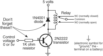
Figure 22-4 A relay can be used to electronically turn a motor on and off. A transistor and a resistor drive the relay; you control the operation of the relay by applying 0 or 5 volts as a control voltage.
![]() Gates are inputs or outputs on a digital circuit, such as from a computer or a microcontroller. As you might guess, you’d use an output gate when operating a relay via a digital circuit.
Gates are inputs or outputs on a digital circuit, such as from a computer or a microcontroller. As you might guess, you’d use an output gate when operating a relay via a digital circuit.
In this circuit, LOW turns the relay off and HIGH turns it on. The relay can be operated from most any digital gate. The chapters in Part 5 deal much more extensively with using electronic and computerized control. If you’re wanting to try relays, familiarize yourself with the wiring diagram in Figure 22-4. It will prepare you for these later chapters.
CONTROLLING DIRECTION VIA RELAY
Changing the direction of the motor is only a little more difficult using relays than turning it on and off. As with the manual switches in the previous section, this requires a DPDT relay, wired in series after the on/off relay just described. Refer to Figure 22-5 for how these two relays are connected. With the switch contacts in the DPTD relay in one position, the motor turns clockwise. Activate the relay, and the contacts change positions, turning the motor counterclockwise.
Again, you easily control the direction relay with digital signals. Logical 0 makes the motor turn in one direction (let’s say forward), and logical 1 makes the motor turn in the other direction.
You need two relays, not just one, to duplicate the functionality you enjoyed with the DPDT center-off switch. An SPST relay is used to turn the motor on and off, and a DPDT relay is used to control the direction of the motor.
You can see how to control the operation and direction of a motor using just two signals (data bits) from a digital circuit like a computer or microcontroller. Since most robot designs incorporate two drive motors, you can control the movement and direction of your robot with just four data bits. In fact, this is true for all the electronic motor control schemes in this chapter.

Figure 22-5 How to combine two relays to fully control a motor: turn it off and on, and reverse direction. The top relay is a single-pole type; the bottom relay is a double-pole type.
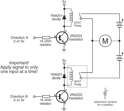
Figure 22-6 An alternative method for controlling a motor is to use two single-pole relays and a split power supply (it provides both positive and negative voltage; this can be done by simply combining two separate battery packs, as shown). With no input signal, the motor doesn’t turn.
CREATING A RELAY HALF-BRIDGE
The SPST/DPDT method described here is the electrical equivalent of using switches, and it works with a wide variety of motors you might encounter in your robot travels. But there’s yet another, and even simpler, method for controlling small, low-voltage hobby DC motors when using relays. It’s ideally suited for those motors that are meant to be run from 1.5 to 3 volts, like those in the very popular Tamiya Twin Motor Gearbox kit.
Figure 22-6 illustrates using two SPST relays to make what’s called a half-bridge. To make this work, you need a pair of battery packs, as shown. One pack provides the + positive voltage to the motor, and the other pack provides the − negative voltage.
You can use a pair of two-cell AA battery holders to power the motor, using either alkaline or rechargeable NiCd or NiMH batteries. When using alkalines, the voltage for each battery holder is 3 volts; it’s 2.4 volts when using rechargeables. Either voltage is fine when using the Tamiya Twin Motor Gearbox or a DC motor of similar design.
Follow this table to control the motor, being careful to never turn both relays on at the same time.

If you prefer an all-electronic approach, see the next sections on using transistors, where the half-bridge concept comes up again.
CURRENT SPECS FOR RELAYS
When selecting relays for your robot, make sure the contacts are rated for the motors you are using. All relays carry contact ratings, and they vary from a low of about 0.5 amp to over 50 amps, at 125 volts. Higher-capacity relays are larger and require more current to operate. This means they need bigger transistors to trigger them and require much more care in selecting all the components in the system. Not very pretty.
As this book is primarily about creating amateur robots under about 20 to 30 pounds, you’ll be using smaller motors, which means smaller relays. For the robots described in this book, you don’t need a relay rated higher than 2 or 3 amps. If you plan on building bigger robots with much bigger motors, you should consider the motor bridge module, detailed later in this chapter.
SIMPLIFIED RELAY DRIVER ELECTRONICS
With two motors you need four relays, which means four transistors, four diodes, and four resistors. What are these extra components for?
![]() The transistors are used to boost the current from the digital gate (for example, from your microcontroller), as not all gates have sufficient current to directly drive the relay. The transistors act as current amplifiers.
The transistors are used to boost the current from the digital gate (for example, from your microcontroller), as not all gates have sufficient current to directly drive the relay. The transistors act as current amplifiers.
![]() The diodes protect the transistors from current that flows backward from the relay coil when it is switched off. This happens because, when the relay coil is deengergized, some of the current that was flowing through it is regurgitated back out. This back EMF (EMF stands for electromotive force) can damage the transistor; the diode prevents this mess from happening.
The diodes protect the transistors from current that flows backward from the relay coil when it is switched off. This happens because, when the relay coil is deengergized, some of the current that was flowing through it is regurgitated back out. This back EMF (EMF stands for electromotive force) can damage the transistor; the diode prevents this mess from happening.
![]() The resistors control the amount of current flowing from the digital gate to the transistor. Without the resistor, the transistor would suck up too much current and possibly damage the gate.
The resistors control the amount of current flowing from the digital gate to the transistor. Without the resistor, the transistor would suck up too much current and possibly damage the gate.
A typical value for these resistors is between 1 kΩ (1000 ohms) and 4.7 kΩ (4700 ohms), assuming 5-volt circuitry. The lower the value of the resistor, the more current will flow from the gate and to the base of the transistor. Use the 1 kΩ value for larger relays that need more current; otherwise, select a higher value.
Use the highest-value resistor connected to the base of the transistor that allows for reliable operation of the relay. You might start with 4.7 kΩ and work downward until you find a resistor value that works best for your specific circuit.
The transistor-resistor-diode combination is the typical way of connecting a relay to the rest of your electronics. But you can save some space and wiring time by using a single 16-pin IC that has everything built in. The ULN2003 integrated circuit contains seven drivers; each driver is the equivalent of the transistor-diode-resistor combo in the previous examples.
To use, connect the control gate to a driver input, and connect its output to the relay, as shown in Figure 22-7. The illustration shows using only one of the available seven drivers. You can use the remaining drivers for other relays or even something else completely—like lighting up some superbright light-emitting diodes. If a driver is not used, disable it by connecting its input to ground. Leave its output unconnected.

Figure 22-7 The ULN2003 Darlington array integrated circuit contains seven independent drive circuits. These drive circuits include the flyback diode shown in the previous relay diagrams. The ULN2003 is a simpler method when using many relays.
You may see similar circuit diagrams showing diodes used on the outputs of the ULN2003. That’s okay. The chip has its own diodes built in, but some designers like to take the extra precaution and add their own. For the smallish relays typically used in hobby robots, the extra diodes are not usually needed, but you can add them if you wish.
Motor Control by Bipolar Transistor
No, bipolar transistors don’t exhibit manic-depressive behavior. In this case, bipolar is merely the term used to describe their internal construction—which we won’t be getting into here since it’s not particularly relevant (besides, there are, like, 10,000 books and Web sites that already talk all about it). There are other types of transistors, but the ones we’re interested in for the time being are the bipolar variety.
Bipolar transistors are more accurately known as bipolar junction transistors, or BJTs. Same thing, slightly more words.
For robotics motor control, you use a bipolar transistor much as you would a switch. In fact, the transistor acts just like a switch: apply or remove current, and the transistor (switch) turns on or off. In order to do its work as a motor control switch, the transistor needs a few extra common electronic components, specifically, a resistor and a diode. The purpose of these are described shortly.
BASIC TRANSISTOR MOTOR CONTROL
See Figure 22-8 for the most basic implementation of using a transistor to operate a motor. A digital LOW or HIGH signal is applied to the input of the transistor circuit. Depending on whether the input is LOW or HIGH, the motor turns on or it turns off.
![]() When you connect the Motor control input to 5 volts (HIGH), the motor turns.
When you connect the Motor control input to 5 volts (HIGH), the motor turns.

Figure 22-8 Fully electronic control of a motor is done using a transistor. This simple circuit starts and stops a motor, depending on the input signal. Select the value of the resistor so that the transistor switches fully on when the input signal is applied (the motor should turn at almost full speed).
![]() When you connect the Motor control input to the ground connection (LOW), the motor stops.
When you connect the Motor control input to the ground connection (LOW), the motor stops.
Transistors of the type shown in Figure 22-8 exhibit an inherent voltage drop between its collector (“C”) and emitter (“E”) connections. The drop is usually about 0.7 volt. It’s enough that you may notice your motor runs a bit slower than when it’s directly connected to the battery. This side effect can be largely avoided by using MOSFET transistors, described below.
Figure 22-9 goes a step further, creating a half-bridge using a two bipolar transistors. One transistor is the NPN type, and the other is a PNP type (see Chapter 31, “Common Electronic Components for Robotics,” for more information on this terminology). It’s best if you use so-called complementary pairs, NPN and PNP transistors that have similar specifications. Refer to the control table in Figure 22-9 for operating the motor. It’s a little unusual because of the use of both NPN and PNP transistors.
Note the use of diodes. When current to the motor is removed, the motor continues to spin until it comes to a natural stop. While spinning, the motor creates a backward-flowing current, which could damage transistor. When diodes are used in this fashion they are often called by various descriptive names—flyback diodes, snubber diodes, free-wheeling diodes, suppression diodes, and a bunch of others. They all mean the same thing; the different terms describe their function, not their type.

Figure 22-9 Simple split-supply motor control circuit, using two batteries (or battery packs) wired in series. Note that the transistors are different types: one is an NPN type, and one is a PNP type.
You need two battery sources to provide the split voltage necessary for this circuit to run. Use a pair of two-cell battery holders, and wire them as shown.
FULL-BRIDGE TRANSISTOR CONTROL
A more elaborate form of transistor motor control uses the full-bridge, also called an H-bridge. The “H” comes from the way the motor is connected to its control circuitry, looking a wee bit like the letter H.
H-bridges require four transistors, along with associated components—resistors, flyback diodes, and perhaps more, depending on the design. They’re harder to build, and harder to get right. Given the availability of other motor control circuitry, it makes more sense to use these other techniques, which tend to be easier and cheaper.
Instead, you can use MOSFET transistors, as described in the following section, or rely on one of the many low-cost motor bridge ICs or modules. Those are covered later in this chapter. Both provide more flexibility, and they are often cheaper and easier to build.
Motor Control by Power MOSFET Transistor
MOSFET stands for “metal oxide semiconductor field effect transistor.” Metal oxide indicates the process used to manufacture them, and field effect refers to the way the transistor conducts current. Power MOSFET is a further classification that indicates the device is intended to drive some kind of load, like a motor.
MOSFETs look like bipolar transistors (they come in the same type of packages), but internally there are some important differences. First, due to their MOS construction, they are more susceptible to being damaged by static electricity. Always keep the protective foam around the terminals of the device until you’re ready to use it.
Second, the names of the terminals are different from what you find on bipolar transistors. These variations are discussed in more depth in Chapter 31, “Common Electronic Components for Robotics,” but for now just know that if you connect a MOSFET to your circuit incorrectly, odds are great that it’ll be destroyed the instant you turn on the power. Bipolar transistors aren’t usually so sensitive.
BASIC MOSFET MOTOR CONTROL SWITCH
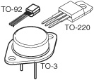
A commonly available power MOSFET is the IRF5xx series, such as the IRF510, IRF520, and so on. These are available in the popular TO-220-style transistor case. These devices can control several amps of current, when on a suitable metal heat sink. The heat sink is a piece of metal that provides a large surface area to draw heat away from the MOSFET.
A basic circuit that uses a commonly available IRF510 power MOSFET is shown in Figure 22-10. It’s a simple on/off switch to control a motor. Apply a 5-volt signal to the gate connection of the transistor, and the motor is turned on. Resistors are used for additional protection of the circuit controlling the transistor.
Notice the Motor voltage label. The voltage to your motor can be different from the voltage that controls the MOSFET transistor. Often, the control electronics in your robot are powered by 5 volts; the voltage to your motors can be 5 volts or over, up to the specified limit of the MOSFET, which is often at least 20 or 30 volts. In the case of the IRF510, the voltage limit is 100 volts.
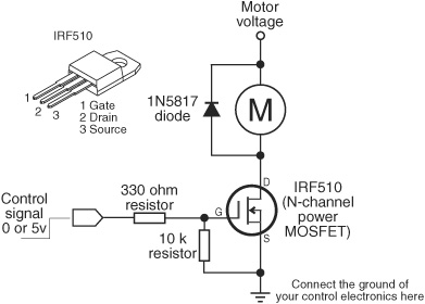
Figure 22-10 A MOSFET power transistor provides nearly the full voltage to the motor when it is turned on.
The IRF510 is routinely available from many online sources, and it costs under $1.50.
MOTOR H-BRIDGE USING MOSFET TRANSISTORS
Figure 22-11 shows the basic concept of the MOSFET transistor H-bridge. The gates of the transistors are connected to either ground or 5 volts. Turning on Q1/Q4 causes current to flow through the motor in one direction, making the motor spin clockwise. Turning on Q2/Q3 causes the current to flow through the motor in the opposite direction. The result: The motor spins counterclockwise.
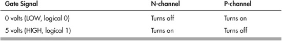
The two types of MOSFET—N-channel and P-channel—refer to the microscopic conductive channel found inside the device. The two types differ in their chemical makeup, which in turn affects how the devices conduct electrons. The arrangement shown in the circuit takes advantage of N-and P-channel behavior to build an H-bridge that acts as close to a mechanical switch as possible.
Note that “turning on” an N-channel or P-channel MOSFET is relative and, for a P-channel transistor, may work opposite to what you think:
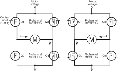
Figure 22-11 A (very) basic H-bridge motor control circuit, using four MOSFET transistors. Note that the two uppermost transistors are P-channel type; the two lower transistors are N-channel type. Don’t get these crossed up.
Unlike bipolar transistors, which exhibit a drop in voltage when current is passed through them, MOSFET transistors pass through nearly all of the volts to the motor.
The N-and P-channel MOSFET transistors you use should be complementary pairs, that is, transistors that share similar specifications. This provides a balance in current-carrying capability. For example, you might use IRF530/IRF9530 or IRF540/IRF9540. Not all MOSFETs use such convenient numbering sequences to indicate pairing. You can consult a basic data book to find complementary pairs, and be sure to read the specifications provided by online retailers. Most retailers provide direct links to datasheets provided by the MOSFET manufacturers, and you’re encouraged to review them and compare specifications.
![]()
There are many ways to build MOSFET H-bridges, and each method has its distinct advantages. Rather than trying to cover them here—which wouldn’t do them justice—see the bonus H-bridge projects on the RBB Online Support site (refer to Appendix A for details). Included are several tested variations, from fairly simple to somewhat complex.
COMMON DESIGN GOALS FOR TRANSISTOR H-BRIDGES
If you’d like to design your own MOSFET transistor H-bridge, keep these basic design goals in mind.
First, the transistors you choose must be capable of handing the current draw demanded by the motor. Refer to the motor specifications to determine their maximum current draw, or test it yourself using the steps in Chapter 21, “Choosing the Right Motor.”
Most motors draw at least 500 milliamps, and this exceeds the current-carrying capacity of MOSFETs that come in the smaller TO-92 package. For most motors you work with, stick with the devices in the TO-220 or TO-3 packages.
On larger-power MOSFETs, the case of the transistor doubles as the drain terminal. This is important if you mount the transistors on a common heat sink, and especially when you ground the heat sink to the metal frame of the robot. Avoid the hassles of potential short circuits by getting a set of insulated transistor-mounting kits. These insulate the transistors electrically but still allow the heat sink to sink heat.
When using transistors in TO-220 or TO-3 packages, if you place the transistors close together on a circuit board be sure none of the metal cases touch one another.
Most H-bridge designs use flyback diodes placed in parallel with each transistor. Without these, the back EMF from the motor could damage the transistor. You’ll know this has happened if the transistor constantly runs the motor, but at a reduced voltage. While most modern power MOSFET transistors include a diode as part of its internal construction, many robo-builders suggest adding your own external diodes. A fast-acting Schottky diode, such as the 1N5817, is usually a good choice when using small to medium-size motors.
And finally, remember that motors produce lots of noise. You’ll want to place an aluminum or tantalum electrolytic capactor (47 μF to 330 μF) across the motor voltage and ground connections, as close to the transistors as possible.
Motor Control by Bridge Module
Circuits for controlling motors are big business, and it shouldn’t come as a surprise that dozens of companies offer all-in-one solutions for running motors through fully electronic means. These products range from inexpensive $2 integrated circuits to sophisticated modules costing tens of thousands of dollars. Of course, we’ll confine our discussion to the low end of this scale!
Motor control modules incorporate the H-bridge design you learned about in the previous section. The module may consist of just an IC, or it may be a premade circuit board with the H-bridge electronics on it. Either way, motor control bridges have two or more pins on them for connection to control electronics and, of course, connections to power and to the motors.
Typical functions for the pins are:
![]() Motor power. Connect these to the battery or other source powering the motors. I like to use a completely separate battery pack for the motors and the rest of the robot’s electronics. Using the motor power pins on the motor bridge, this is very easy to do.
Motor power. Connect these to the battery or other source powering the motors. I like to use a completely separate battery pack for the motors and the rest of the robot’s electronics. Using the motor power pins on the motor bridge, this is very easy to do.
![]() Motor enable. When enabled, the motor turns on. When disabled, the motor turns off. Some bridges let the motor “float” when disabled; that is, the motor coasts to a stop. On other bridges, disabling the motor causes a full or partial short across the motor terminals, which acts as a brake to stop the motor very quickly.
Motor enable. When enabled, the motor turns on. When disabled, the motor turns off. Some bridges let the motor “float” when disabled; that is, the motor coasts to a stop. On other bridges, disabling the motor causes a full or partial short across the motor terminals, which acts as a brake to stop the motor very quickly.
![]() Direction. Setting the direction pin changes the direction of the motor.
Direction. Setting the direction pin changes the direction of the motor.
![]() PWM. Most H-bridge motor control ICs are used to control not only the direction and power of the motor but its speed as well. The typical means used to vary the speed of a motor is with pulse width modulation, or PWM. This topic is described more fully under “Controlling the Speed of a DC Motor.” On many H-bridge ICs, the motor enable and PWM input are the same
PWM. Most H-bridge motor control ICs are used to control not only the direction and power of the motor but its speed as well. The typical means used to vary the speed of a motor is with pulse width modulation, or PWM. This topic is described more fully under “Controlling the Speed of a DC Motor.” On many H-bridge ICs, the motor enable and PWM input are the same
![]() Brake. On bridges that allow the motor to float when the enable pin is disengaged, a separate brake input is often used to specifically control the braking action of the motor.
Brake. On bridges that allow the motor to float when the enable pin is disengaged, a separate brake input is often used to specifically control the braking action of the motor.
![]() Motor out. These are outputs for connecting to the motor.
Motor out. These are outputs for connecting to the motor.
The better motor control bridges incorporate overcurrent protection circuitry, which prevents them from being damaged if the motor pulls too much current and overheats the chip. Some even provide for current sense, useful when you want to determine if the robot has become stuck.
Recall from earlier in this chapter that DC motors will draw the most current when they are stalled. If the robot gets caught on something and can’t budge, the motors will stop, and the current draw will spike.
USING THE L293D AND 754410 MOTOR DRIVER ICS
Among the most common—and least expensive—motor bridge ICs are the L293D and its close cousin, the 754410. Both come in small 16-pin IC packages, and their hookup is identical. The big difference between the two is the maximum amount of current that the chip can handle.
![]() The L293D can supply up to 600 mA of current (continuous, per channel).
The L293D can supply up to 600 mA of current (continuous, per channel).
![]() The 754410 can supply up to 1.1 A of current (continuous, per channel).
The 754410 can supply up to 1.1 A of current (continuous, per channel).
On both chips, the supply voltage ranges from 4.5 to 36 volts, and they have connections for not just one motor but two.
From here on out I’ll refer just to the L293D, but know the discussion applies to the 754410 as well.
When buying the L293D, be sure it has a D at the end of it. “D” denotes diodes. Recall the use of diodes used to protect components in the transistorized H-bridges described earlier in this chapter. The L293D (and the 754410) have these diodes built in. If you don’t get the D version of the L293, you’ll need to add these diodes yourself.
While we’re on the subject of diodes: There is some disagreement among robo-builders about whether the diodes built into the 754410 are intended for flyback protection. The datasheet for the 754410 is not clear on the subject. Adding to the confusion is that several versions of the datasheet contain other errors. If you want to be sure that the 754410 is fully protected, you can add external diodes, such as 1N5817. But if playing safe is the key, this suggestion applies equally to the L293D and any other motor bridge IC.
Figure 22-12 shows the basic connection for the L293D to a pair of motors. Notice the two power pins for the L293D: one is to power the IC, and it should be 5 volts. The other is the power for the motor, and that can be up to 36 volts. The minimum allowed motor voltage is 4.5 volts.
Each motor is controlled by a set of three pins, also called input lines. The motors are referenced as Motor1 and Motor2.
For Motor1, the control lines are labeled Input1, Input2, and Enable1. For Motor2 the lines are marked Input3, Input4, and Enable2.
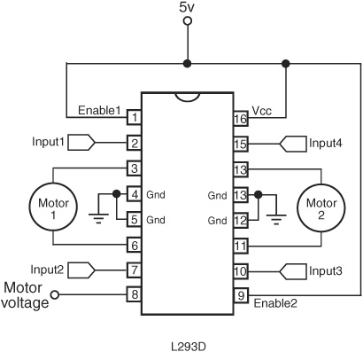
Figure 22-12 H-bridge integrated circuits incorporate all the necessary electronics to drive a motor.
In order to activate Motor1, the Enable1 line must be HIGH. You then control the motor and its direction by applying a LOW or HIGH signal to the Input1 and Input2 lines, as shown in this table.
Motor1
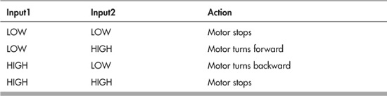
Controlling Motor2 is the same, except it uses Input3 and Input4.
The enable lines are also used to control the speed of the motor (Enable1 for Motor1, and Enable2 for Motor2). Instead of a constant HIGH signal, you can apply a rapid succession of LOW/HIGH pulses; the length of the pulses determines how fast the motor goes. For more, see “Controlling the Speed of a DC Motor,” later in this chapter.
The L293 series and 754410 chips have a “fast motor stop” feature when the Enable line is HIGH and both Inputs are LOW or HIGH (either, doesn’t matter). Depending on the motor, this may not produce much of a braking effect. If you need to quickly stop the motor, momentarily reverse its direction, then stop it. If you don’t want the “fast motor stop” feature, disable the motor by bringing the Enable line LOW.
The four center pins of the L293D serve as the IC’s ground connectors and can also be used as part of a heat sink. In order for the chip to drive its maximum current, you should add a larger metal heat sink over the IC. You can buy these premade or solder on strips of bare (uncoated) copper metal pieces to the center pins in a kind of “wing” arrangement.
BONUS PROJECT: USING THE L298 MOTOR DRIVER IC
The L298 is another popular motor driver IC, capable of handling up to 2 amps per motor. Using it is a bit more involved than using the L293D, though the principle of operation is the same. See the RBB Online Support site for a bonus project using the L298, including programming examples for the Arduino and PICAXE microcontrollers.
“INTELLIGENT” MOTOR BRIDGE MODULES
A recent trend is serial motor control, which essentially consists of “set and forget” modules that do most of the hard work for you. Using a microcontroller attached to the module via a simple serial communications connection, you command the motor to start, stop, and reverse. All modern microcontrollers support serial communications in one form or another, so this technically is available on any robot that uses a microcontroller as a central brain.
What’s more, you can order the motor to change speed, without having to worry about the complexities of motor speed control (described in the next section). The number of speeds available to you depends on the module, but it’s not uncommon to have at least 64 speed steps—all the way from a slow crawl to full pedal-to-the-metal bore.
Many of these intelligent bridge modules are available in single-or dual-motor versions, with current capacities of 50, 75, even 100 amps—ideal if you’re building a very large or combat robot.
Also available are ESC motor speed controllers, originally intended for use with high-speed R/C racing vehicles. Find these at any R/C hobby store. Though ESC motor speed controllers are designed for use with R/C receivers, you can use an ordinary microcontroller to simulate the signals that it expects to see. Just treat it like a servo motor.
Controlling the Speed of a DC Motor
There will be plenty of times when you’ll want the motors in your robot to go a little slower or perhaps track at a predefined speed. Speed control with continuous DC motors is a science in its own right, but the fundamentals are quite straightforward.
NOT THE WAY TO DO IT
Before exploring the right way to control the speed of motors, let’s examine how not to do it. Many robot experimenters first attempt to vary the speed of a motor by using a potentiometer. While this scheme can work, it wastes a lot of energy. Turning up the resistance of the potentiometer (which is a variable resistor) decreases the speed of the motor, but it also causes excess current to flow through the pot. That current creates heat and draws off precious battery power.
BASIC SPEED CONTROL
A better way is to feed the motor short on/off pulses of its usual voltage. The pulses are very fast, so fast that the motor doesn’t have time to respond to each on/off change. What happens is that the motor ends up averaging the ons with the offs, so, effectively, less voltage gets to the motor.
This system of motor speed control is called pulse width modulation, or PWM. It is the basis of just about all motor speed control circuits. The longer the duration of the pulses, the faster the motor because it is getting full power for a longer period of time. The shorter the duration of the pulses, the slower the motor.
Check out Figure 22-13, which shows the on and off nature of PWM. The time between each pulse is called the period, and it’s usually just a brief moment in time—microseconds. In the typical PWM system, there may be from 500 to over 20,000 of these periods each second.
Notice that the power or voltage delivered to the motor does not change—it’s always 5 volts (or 6 volts, or 12 volts, or whatever). The only thing that changes is the amount of time the motor is provided with this voltage. The longer the on time in relation to the off time, the more power the motors gets. Most motors function adequately at PWM ratios of 25 percent or higher. Depending on the motor and other factors, at lower PWM rates the motor may not receive enough power to turn its load.

Figure 22-13 The speed of nearly all DC motors may be varied by changing the duty cycle (on versus off times) of its supply voltage. The longer the on time, the faster the motor will turn.
Remember: The frequency of the pulses—how many occur in a second—does not change, just their relative on and off times. PWM frequencies of 1 kHz (1000 cycles per second) to over 20 kHz are commonly used, depending on the motor.
Unless you have a specification sheet from the manufacturer of the motor, you may have to do some experimentation to arrive at the “ideal” pulse frequency to use. You want to select the frequency that offers maximum power with minimum current draw.
Bonus Projects: Interfacing to Motor Bridge Modules
I’ve added a number of bonus motor bridge projects to the RBB Online Support site, including using several brands of serial motor speed controllers with the Arduino microcontroller. You’ll find connection schematics, programming code, and parts lists.
Also included are hands-on sample code projects for using the venerable L293D, and the L298, with the three controllers highlighted in this book: Arduino, PICAXE, and BASIC Stamp. See Appendix A for more details about the RBB Online Support site.
The sample code demonstrates motor direction control, plus PWM speed control.