
Chapter 27
Build Robots with Legs
Do you enjoy challenges? I mean the really tough nuts that are hard to crack, the stuff that keeps you up at night as you try to work through the problems? If so, then maybe you’re ready to build a walking machine.
Legs are biologically inspired solutions to that old problem of how to get your robot from here to there. And not only as a means to mobilize your creation, but to step over common obstacles like yesterday’s lunch bag, your dirty socks, and the family turtle—stuff that might confound the typical robot with wheels or treads.
In this chapter you’ll learn about the role of legs in creating mobile robots, and the special requirements and limitations they impose. You’ll read about ready-made solutions, as well as several designs for making your own six-legged bots on a budget and from scratch.
An Overview of Leggy Robots
With legs, a robot can live among humans, ideally without any kind of special adjustments or alterations to the environment. Ramps, curbs, steps, stairs, and cracks in the sidewalk all pose no more of a problem for the robot than they do for any other ambulatory human being.
As of this writing, human-size legged robots that can go anywhere and do anything are still the province of science fiction. Less ambitious are the full-scale walking robots of industrial and educational research that show promise but cost a fortune and are known to fall over on their batteries now and then.
Small-scale legged robots are another matter. With a modest inventory of servo motors and some specially crafted brackets, you can construct walking bots with two, four, six, and even more legs. Though they’re more expensive and more demanding to build than robots with wheels or tank treads, constructing a programmable walkerbot is well within the reach of the garage-shop tinkerer.

Legged robots aren’t for beginners. If you’re just starting out, first hone your skills by constructing a couple of wheeled bots. This applies whether you buy a ready-made kit of parts or build it from scratch. Walking robots require greater precision and attention to detail—when improperly constructed, they rattle apart, may simply not work, or fall over in a crashing heap.
NUMBER OF LEGS
This concept was introduced in Chapter 2, “Anatomy of a Robot,” and Chapter 20, “Moving Your Robot,” but it bears repeating here. The most common forms of legged bots are:
Bipeds, which walk on two legs. In a true bipedal robot, one leg lifts up to make a step. Balance can be tricky when the robot has just one foot on the ground, making this type among the hardest to master. The alternative is the “shuffling” walking robot common in toys whose legs don’t actually lift up and down.
Quadrupeds, meaning four legs. The more sophisticated four-legged bots demonstrate a variety of walking styles, some mimicking animals. These can be tricky to build, because each leg needs three separate joints—otherwise known as degrees of freedom, or DOF—in order to keep balance and make turns.
Hexapods, for which six legs provide excellent balance and mobility. Among walking robots, they’re the most common and, despite the extra legs, the easiest to build.
And, of course, there are examples of robots with other appendage counts. One-legged robots, or hoppers, look like pogo sticks without a rider. They move around by bouncing.
Robots with eight or more legs, or multipods, include a wide variety of wild and crazy designs. These include segmented bots, which behave (and somewhat look) like snakes, worms, or caterpillars. Each segment is controlled by one or more motors not unlike the joints in a walking robot.
A few experimental walking robots employ an odd number of legs. If four are too few, and six too many, why not build a bot with five legs? And finally, hybrid robots may combine legs with wheels or tracks. An example is a 4WD robot that has two legs in the front. The legs can help to lift the robot up steps and over obstacles and, if jointed properly, can serve as manipulators. Pretty rad stuff.
STATIC VERSUS DYNAMIC BALANCE
Balance is the ability of the robot to remain upright when it’s standing on its legs. Balance can be static or dynamic.

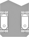
![]() Static balance means the legs provide a natural stability, using any (or a combination) of several techniques. In four- and six-legged bots, the most common static balance comes from always having at least three legs on the ground at the same time, forming a tripod stance. With all types, static balance is improved by having a low center of gravity; much of the weight is at least 50 percent below the overall height of the robot.
Static balance means the legs provide a natural stability, using any (or a combination) of several techniques. In four- and six-legged bots, the most common static balance comes from always having at least three legs on the ground at the same time, forming a tripod stance. With all types, static balance is improved by having a low center of gravity; much of the weight is at least 50 percent below the overall height of the robot.
![]() Dynamic balance means the robot uses sensors to keep itself upright. When the bot feels it’s starting to tip over, the sensors activate one or more motors to shift the robot’s weight one way or another. As the weight shifts, the tilt is negated, and the robot is kept upright.
Dynamic balance means the robot uses sensors to keep itself upright. When the bot feels it’s starting to tip over, the sensors activate one or more motors to shift the robot’s weight one way or another. As the weight shifts, the tilt is negated, and the robot is kept upright.
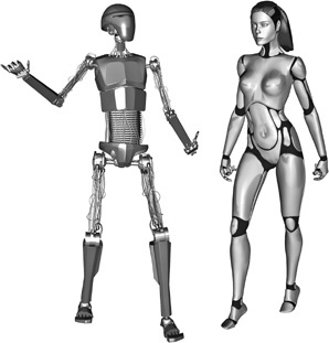
Figure 27-1 Bipeds in both android and humanoid forms.
BIPEDS: ANDROID OR HUMANOID
The terms android and humanoid are used to describe robots that are modeled after the human form (Figure 27-1). There’s a head, torso, two legs, and at least one arm. Though usage varies, the terms don’t mean exactly the same thing. An android is a robot designed to look as much like a human being as possible, either male, female, or an androgynous mix of the two (androgyny is where we get the term andr-oid, meaning “like male and female”). The robot has eyes where we have eyes, a nose, mouth, ears, and other things that make us look like we do.
Conversely—and somewhat confusingly—a humanoid robot is one that shares the basic architecture of a human. It has two legs, with a head at the top, and two arms at the side. Rather than duplicate the appearance of people, it’s meant more to replicate human ability, such as being able to walk through a hallway meant for humans or sit down in a chair meant for humans.
NUMBER OF JOINTS/DEGREES OF FREEDOM
Leg motion is provided by a series of joints. Some joints allow the leg to swing back and forth, while others permit side-to-side motion. The number of joints that provide motion is called the degrees of freedom, or DOF. For the most part, the more DOF, the more agile the robot. For amateur robots the 2- and 3-DOF bot designs are more common.
Except for some unique designs that use clever mechanical linkages, each leg DOF needs a separate motor to control the joint. The more motors, the more expensive the robot; it’s heavier and larger, too. So consider the number of leg DOF when picking a walking robot design. That hexapod with 3-DOF legs looks mighty impressive; just remember it needs 18 motors. It’s not unusual for these kinds of robots to cost upward of $600, and that’s before any microcontrollers or other electronics.
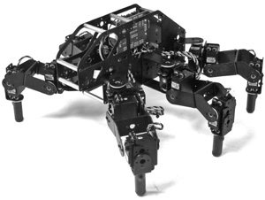
Figure 27-2 Commercially manufactured hexapod kit featuring 3-DOF legs. The extra degree of freedom in the legs provides a more defined stepping action. (Photo courtesy Lynxmotion.)
OPERATING TERRAIN
Bots with 2 DOF per leg work best on smooth, unobstructed surfaces—a kitchen floor or a hallway with wood laminate are good choices. The surfaces shouldn’t be too slick, unless you add rubber pads on the robot’s feet. Otherwise, the contraption will tend to skitter on the floor as it frantically moves its limbs. It’s comical but not too productive.
The more sophisticated 3-DOF robots with four- or six-legs can be used on more challenging terrain. This is because they’re endowed with an additional articulation that permits the legs to literally step up and down rather than just swing in and out, which is typical of the simpler 2-DOF designs. The full leg-lift helps the robot clear low objects and even thick carpet nap.
Many of the more elaborate ready-made walking robot kits are designed with this feature. Figure 27-2 shows an example: its third DOF permits the legs to lift up vertically, clearing obstacles at least 1/2″ to 1″ in height. Of course, these designs are more expensive because they require three servos per leg and additional leg hardware.
Selecting the Best Construction Material
Walking robots need to be strong yet lightweight. The heavier the robot, the less likely it can stand on its own two feet, so to speak. Pine lumber and soft plywood are pretty much out, because they’re too bulky and heavy for the strength they offer.
FYI
There’s lots more about wood, plastic, and metal in the chapters in Part 2 of this book. Be sure to see Chapter 7, “Working with Wood,” Chapter 9, “Working with Plastic,” and Chapter 11, “Working with Metal.
Materials choice, in order of preference, is:
![]() Aluminum, cut and drilled to shape. For walking robots under 1 foot high, thickness ranges from about 20 gauge (0.0320″) to 8 gauge (0.128″). Premade parts are often cut by a powerful waterjet machine controlled by a computer, then bent using special jigs. When building your own, the likely tools are hacksaw, drill press, and bench vise.
Aluminum, cut and drilled to shape. For walking robots under 1 foot high, thickness ranges from about 20 gauge (0.0320″) to 8 gauge (0.128″). Premade parts are often cut by a powerful waterjet machine controlled by a computer, then bent using special jigs. When building your own, the likely tools are hacksaw, drill press, and bench vise.
![]() Polycarbonate plastic is a tough, scratch-resistant material commonly used as a substitute for glass. You can cut it with hand or power tools. A thickness of 1/8″ is ideal for robot making
Polycarbonate plastic is a tough, scratch-resistant material commonly used as a substitute for glass. You can cut it with hand or power tools. A thickness of 1/8″ is ideal for robot making
![]() PVC plastic, in 6mm (about 1/4″) thickness. While not as strong as polycarbonate, PVC is lots easier to work with, requiring nothing more than regular woodworking tools.
PVC plastic, in 6mm (about 1/4″) thickness. While not as strong as polycarbonate, PVC is lots easier to work with, requiring nothing more than regular woodworking tools.
![]() ABS plastic, in 1/8″ or 1/4″ thickness. It’s a bit easier to cut and drill than polycarbonate, and parts can be glued using a common and inexpensive solvent cement.
ABS plastic, in 1/8″ or 1/4″ thickness. It’s a bit easier to cut and drill than polycarbonate, and parts can be glued using a common and inexpensive solvent cement.
![]() Wood, but not just any wood, specifically aircraft-grade birch or other hardwood plywood. The 1/4″ or 3/8″ sheets provide adequate strength, and parts may be glued using a quality wood glue.
Wood, but not just any wood, specifically aircraft-grade birch or other hardwood plywood. The 1/4″ or 3/8″ sheets provide adequate strength, and parts may be glued using a quality wood glue.
![]() Acrylic plastic is one of the least desirable of the materials commonly used to construct walking robots. Though similar in appearance to polycarbonate, it’s not quite as strong and is susceptible to cracking under stress. The repetitive bending of the plastic can permit hairline fractures and “crazes” to form over time.
Acrylic plastic is one of the least desirable of the materials commonly used to construct walking robots. Though similar in appearance to polycarbonate, it’s not quite as strong and is susceptible to cracking under stress. The repetitive bending of the plastic can permit hairline fractures and “crazes” to form over time.
Scratch Build or Parts Kits
Perhaps the hardest aspect of building a walking robot is fabricating the leg pieces. So before starting any legged robot project, take an honest look at your tools, skills, and budget, and decide whether you want to build your own from scratch (that is, from raw materials) or whether you want to assemble a walkerbot from premade parts. Because of the growing popularity of amateur robotics, a number of online sources offer parts specifically designed for constructing legged robots, anything from two legs on up.
BUILD YOUR OWN FROM SCRATCH
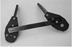
If you have reasonably good shop skills, you can consider making your own walking bot from scratch, using your choice of wood, plastic, or metal. The most common construction in a legged robot is the X-Y joint, so called because a pair of motors produces a linear movement in both the X (right/left) and Y (up/down) planes. Shown in Figure 27-3 is an X-Y joint created using 6mm PVC plastic. A pair of R/C servo motors is attached to the joint using miniature fasteners.

Figure 27-3 Homemade X-Y joint components for constructing a robotic leg (among other things). The parts are fashioned out of wood or plastic.
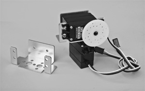
Figure 27-4 A precut and preformed aluminum X-Y joint, available from a number of online specialty robotics retailers.
Plans for the joint parts, which can be constructed using nothing more than hand tools, appear later in this chapter. These same joints are then used to create a fully functional and robust six-legged walking robot, which is provided as a free bonus project on the RBB Online Support site.
BUILD FROM PREMADE PARTS
Numerous sources such as Lynxmotion and Pitsco provide premade parts for X-Y joints. Prefabbed aluminum brackets like the one in Figure 27-4 come cut and drilled to work with most any standard-size servo motor. The bracket weighs about the same as the PVC X-Y joint (half an ounce), but the PVC version is considerably cheaper to build.
Various types of these aluminum brackets can be combined to create different arrangements. For example, you can create an X-Y bracket with an L bracket in order to reconfigure the orientation of the servo motors used for the joint. Among other things, this can be used to provide a more streamlined shape or to create mechanisms for 3-DOF joints.
Some kits with premade parts use modular metal and/or plastic construction and are designed as development systems for building walking and rolling bots. Example: The Bioloid robot sets offer numerous permutations including sophisticated bipedal designs. The kits, which are designed for advanced study, are available in different parts assortments.
BUILD FROM A MIXTURE OF PARTS
There’s nothing stopping you from combining your own homemade parts with prefabbed ones, mixing and matching as needed. For example, you might combine a PVC X-Y joint with a premade L bracket. You might also provide your own chassis for the robot, leaving just the leg pieces as store-bought.
MOTOR SHAFT SUPPORT AND YOKE BRACKETS
The simplest of servo brackets, like the one in Figure 27-3, lack a means to support the load placed on the servo motor by the weight of the leg pieces. This isn’t a major problem for robots that see only occasional use and aren’t too heavy. But it’s something you’ll want to consider as your walkerbots gain weight or are frequently used for show-and-tell.
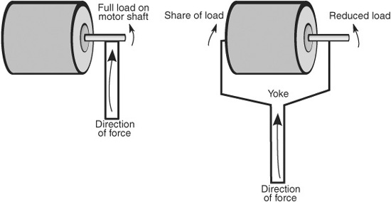
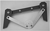
Figure 27-5 A yoke mechanism distributes weight or force so that it’s not all against the shaft of the motor. This helps the motor work more efficiently and last longer.
The most common way to alleviate the strain on the motor is by using a yoke or double-sided bracket (see Figure 27-5). Here, the load on the motor is distributed evenly between the motor shaft and a secondary (and passive) shaft. The two shafts are in line with one another. The second passive shaft can be a steel or aluminum rod, or even a machine screw. The shaft may use ball bearings or bushings to ensure unimpeded rotation.
Note that the X-Y joint plans that appear later in this chapter are sans support. You can add a yoke-style arrangement with nothing more than a third piece of plastic (or wood if that’s your material of choice) that screws onto the bracket opposite the motor shaft.
Leg Power
When it comes to the muscles of a walking robot, radio-controlled servos are the preferred choice; they’re compact and widely available, and they require no special interfacing or drive electronics connected to your robot’s central computer.
Where rolling robots can make do with just about any standard-size R/C servo, legged robots need a bit more attention to the details. Specifically, you need servo motors that provide enough torque to lift the legs and move the robot. It’s not unusual for a six-legged hexapod to weigh several pounds. With underpowered servos, the robot will just sag to the ground, unable to sustain its own weight.
CONTROLLING SERVOS
Recall from Chapter 23, “Using Servo Motors,” that servos require a special pulse signal in order to operate. Typical operating voltage for servos is between 4.8 and 6.0 volts, though many robot builders push to the edges of the envelope and supply 7.2 volts—this increases the torque of the motor by as much as 30 or 40 percent.
Overvolting an R/C servo motor has the potential of burning it out, so you must exercise care if you wish to experiment with this technique. Some brands, and even models within each brand, are more tolerant of the higher voltages than others, so you need to experiment. When using a higher-than-normal voltage with your servos, give them a periodic touch test to make sure they aren’t overheating. Immediately disconnect the servo if it seems to be getting too hot or is putting out an unusual smell.
Because of the heavy demands of the motors in a walking robot, you need to run them from a separate battery supply. When using this arrangement, be absolutely sure that the ground connections of the two battery supplies are connected, or your robot will not function properly.
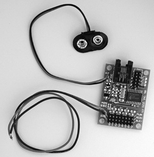
Figure 27-6 The Mini SSC II, a popular serial servo controller capable of operating up to eight R/C servo motors simultaneously. (Photo courtesy Scott Edwards Electronics.)
USING A DEDICATED SERVO CONTROLLER
Legged robots require lots of servos. Rather than hogtie the robot’s main processor with the job of running them all, you can hand it off to a coprocessor instead. That’s the idea of the serial servo controller, or SSC (see Figure 27-6). These compact circuit boards are designed to receive one-time instructions from your robot’s microcontroller on which servos to activate and what position to move them to. The SSC then independently controls the servos without any further intervention by the robot’s controller.
It’s called a serial servo controller because the microcontroller communicates with the SSC via a simple serial communications link. The link can be one-way or two-way. Most microcontrollers provide a simple command structure for sending serial data to another device. For example, the BASIC Stamp offers the serout command, and the Arduino has a SoftwareSerial library that can use any I/O pin as a serial line.
![]()
Check out the RBB Online Support site (see Appendix A for details) for several hands-on examples of using popular SSCs with the Arduino and other microcontrollers.
ANALOG VERSUS DIGITAL SERVOS
As you read in Chapter 23, the most common radio-controlled servos are analog. Digital servos use onboard microcontrollers to enhance their operation. Because of the way digital servos work, they tend to provide more torque and are naturally better suited for use on walking robots. Digital servos are more expensive (sometimes much more expensive), so you’ll want to carefully select the servos you use based on the weight and other design factors of your walkerbots.
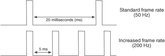
Figure 27-7 The frame rate of pulses applied to an analog servo directly affects its power. Increasing the frame rate can deliver more torque. Not all analog servos can tolerate a frame rate above a certain threshold.
Why are digital servos more powerful? Part of the answer lies in how the motor inside the servo gets juice, and knowing this answer can help you determine if cheaper analog servos might fit the bill.
In an analog servo, the control pulses sent to it act as momentary jolts of current, each jolt energizing the motor and making it go. As shown in Figure 27-7, the normal repetition rate of the pulses is around 20 milliseconds, which equates to 50 Hz (50 times a second).
If the repetition rate—or “frame rate”—is slowed down too much, the motor gets weak and may not even function. Conversely, with a higher frame rate the motor receives more pulses, and its torque increases.
The increase in frame rate is exactly what happens in a digital servo. Even though the servo may get the normal pulses at 50 Hz, internally the electronics in the servo energize the motor at rates in the range of 200 Hz or more.
Most analog servos cannot tolerate a frame rate of 200 Hz … even 100 Hz may be too high. It all depends on the brand and model of servo. If your microcontroller allows you to specify how often the servo is pulsed, you can experiment with different values to find the maximum rate before the motor either stops functioning or becomes erratic.
![]()
Carefully monitor the operation of your servo when altering any of its control signal characteristics. Analog servos that are fed a high rate of pulses may run at a higher current, which causes the motor to dissipate (give off) more heat. If the current and heat get too high, the motor may be permanently damaged.
Beyond a faster rate of pulsing, many digital servos also offer other torque-enhancing features, such as higher-efficiency motor windings and more sophisticated control electronics. The servo itself tends to be better made, able to withstand the higher current, temperatures, and torque exhibited by the motor. Many of the better digital servos use metal gears, which are preferred when the motor has to push heavy loads.
REMEMBER SERVO TORQUE RATINGS
Digital or analog, when selecting a servo for your walking robot take note of its torque rating, which will be listed at either 4.8 or 6 volts (or both). As you learned in Chapter 23, “Using Servo Motors,” the higher the torque, the more power is delivered by the motor. The typical standard servo provides under 50 or 60 oz-in of torque, which is acceptable for desktop robots and smaller walking robots.
For anything larger, you want a servo that delivers 90 oz-in or above. There are a number of standard-size analog and digital servos that offer this torque rating. Very large and heavy walkers need 200+ oz-in of torque, which is practical only with the much more expensive digital servos.
Walking Gaits for Legged Robots
Gait refers to the pattern of leg movement as an animal or insect walks. Gaits can and do differ depending on the speed of travel—a running gait is wholly different from a walking gait. The leg motions are distinctive in each one. So, too, for robots, though almost all are restricted to walking gaits. There aren’t too many legged robots that can run, at least not without falling over and making fools of themselves.
Figure 27-8 shows most common gait of a six-legged robot that has independent control of each leg. This gait is often referred to as an “alternating tripod gait,” because at least three legs are always touching the ground at the same time, providing static balance. (A similar gait, also an alternating tripod, is used when the robot uses legs that are linked together. This gait is described in more detail in “Build a 3-Servo Hexapod,” next.)
The alternating tripod gait goes through a number of sequences, as shown in Figure 27-8. For each side of the tripod, the legs are lifted, lowered, and swept forward or backward in unison. This provides for a reasonably fast walk while still maintaining good static balance as the weight of the robot is shifted from one side to the other.
The legs act either to lift or to power.
![]() Legs are lifted to orient them into a new position. During lift, the leg does not provide propulsion, nor does it contribute to the balance of the robot.
Legs are lifted to orient them into a new position. During lift, the leg does not provide propulsion, nor does it contribute to the balance of the robot.
![]() Legs that power propel the robot in the opposite direction of the movement.
Legs that power propel the robot in the opposite direction of the movement.
To be sure, there are other gaits for six-legged creatures, living or robotic. They include metachronal (or wave) and ripple. Space forbids me from detailing each one of these, but you can learn more about these and others with a Web search.

Figure 27-8 The alternating tripod gait common in hexapod robots. Three legs always touch the ground in a tripod arrangement. The robot moves by alternating the side of the triangle that’s on the ground and “sweeping” those legs in the opposite direction of intended travel.
Build a 3-Servo Hexapod
Using simple linkages, you can construct a fully functional hexapod walking robot powered by just three servos. Figure 27-9 shows the completed Hex3Bot, which measures 7″ by 10″, and stands 3-1/2″ tall. Weight is only 11.5 ounces when constructed out of 6mm expanded PVC, the recommended material. (You can also use 1/4″ aircraft-grade plywood, but this will make the robot weigh a bit more.)
Like any hexapod robot with static balance, the Hex3Bot keeps from falling over by always having at least three legs—in a tripod arrangement—on the ground at any time. Walking is accomplished by sweeping the front and rear legs on each side in alternating cycles. The middle legs, which only lift up and down, act to “rock” the robot from side to side, providing the third leg of the tripod.
The walking gait is composed of a three-step sequence, shown in Figure 27-10:
1. Lift right or left middle leg. Only one leg is down at any time. The robot tilts to the side opposite the middle leg that is down.
2. Power sweep the front/rear legs that are touching the ground. The robot propels forward.
3. Non–power sweep the front/rear legs that are not touching the ground. The robot doesn’t move in this step; it merely positions the legs for the next sequence.
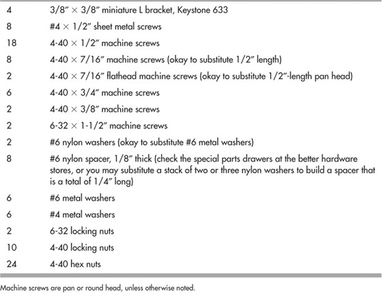
PARTS YOU NEED
In addition to fastener hardware (see the section “Assemble to Complete the Hex3Bot” for a list), you need the following stuff to build this robot:
![]() 1 piece of 12″ × 12″ 6mm-thick expanded PCV (preferred), or 1/4″ birch or other hard-wood aircraft-grade plywood
1 piece of 12″ × 12″ 6mm-thick expanded PCV (preferred), or 1/4″ birch or other hard-wood aircraft-grade plywood
![]() 3 standard-size servo motors.
3 standard-size servo motors.
![]() 2 12″ lengths of 1/2″-wide by 0.016″-thick brass strips (available at hobby and craft stores, such as K&S Metals, #1412110231)
2 12″ lengths of 1/2″-wide by 0.016″-thick brass strips (available at hobby and craft stores, such as K&S Metals, #1412110231)

Figure 27-9 The completed Hex3Bot walking robot, which uses three R/C servo motors to get around. The Hex3Bot is an example of a hexapod design that uses linked legs.
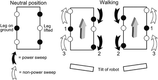
Figure 27-10 Walking gait of the Hex3Bot. The center legs serve to tilt the robot to one side or another. Motion is accomplishing by pushing the left or right legs when they are on the ground. The numbers 1, 2, and 3 are the sequence of steps used when walking.
![]() 2 six-arm (“star”) servo hubs (they usually come with the servo)
2 six-arm (“star”) servo hubs (they usually come with the servo)
![]() 1 large round servo hub (usually comes with the servo)
1 large round servo hub (usually comes with the servo)
You need the following fasteners to complete the Hex3Bot (get extras in case you lose any during construction):
CUT AND CONSTRUCT THE LEGS
All holes are 1/8″ unless otherwise noted.
Begin by constructing the leg pieces; a cutting and drilling template is provided in Figure 27-11. The four front and rear legs are composed of two pieces—upper and lower. The middle legs have just one piece. The “feet” (bottoms) of all the leg pieces are cut at a 30° angle. Use a protractor to mark the angle. It’s okay if it’s a degree or two off, but try to be as accurate as possible to match all cuts.
Assemble the upper leg and lower leg pieces using #4 sheet metal (not wood) screws (see Figure 27-12). Using a pencil and the top leg as a template, mark the placement for the mounting in the edge of the bottom leg. Prepare a pilot hole for the screw with a small 1/16″ bit. It doesn’t need to be a deep hole. Fasten the leg pieces using the sheet metal screws. They’ll self-tap as you tighten them.
Notice that there are two styles of legs: the rear legs, which include a hub for connecting to a servo, and the front legs, which attach to the robot using a screw and lock nut. You will make two of each style. I’ve set the hole spacing for a six-arm “star” servo hub, common on Futaba and Futaba-style standard-size servos. If you use a different hub, you’ll need to adjust the spacing of the holes. Drill out the holes in the hub to accommodate the 4-40 machine screws.
Use two 4-40 × 1/2″ machine screws and nuts to attach the servo hub to the underside of the upper leg piece. See Figure 27-13 for a pictorial view of the leg pieces, separate and assembled. Note the extra chamfering added to the corners of the upper leg pieces. This isn’t required, but it makes the legs look a bit more streamlined.
CUT THE BASE PIECES
Follow the cutting and drilling guide in Figure 27-14 to prepare the base, middle spar, middle leg servo mount, and the two front leg spacer spars. Be careful when drilling the holes for mounting the servos; these require a fair amount of accuracy.
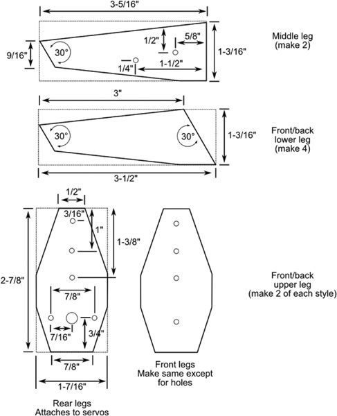
Figure 27-11 Cutting and drilling template for the Hex3Bot’s legs. All holes are 1/8″ except as noted.

Figure 27-12 The legs are assembled by attaching the upper leg piece to the lower piece, using #4 sheet metal screws.
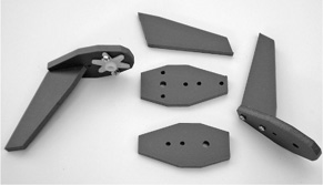
Figure 27-13 The front and rear legs, as cutout pieces and assembled. The rear legs have a six-arm “star” servo horn attached to them.
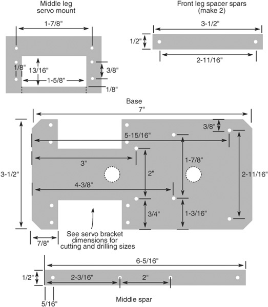
Figure 27-14 Cutting and drilling template for the base pieces for the Hex3Bot. All holes are 1/8″ except as noted in the text.
The two large holes down the middle of the base are for passing wires through. The holes can be most any size and shape—1/2″ is handy—as long as they don’t interfere with the construction of the bot.
Use a 9/16″ bit (to accommodate a 6-32 screw) for the following:
![]() Two holes on the far right of the base
Two holes on the far right of the base
![]() Two holes on the front leg spacer spars
Two holes on the front leg spacer spars
PREPARE THE LINKAGES
The Hex3Bot uses locking nuts for its moving links. The nuts should not be overtightened on their screws, or the robot may have difficulty in moving; nor should they be too loose. Use a screwdriver and wrench (or nut driver) to tighten the locking nuts so that they just begin to impede free movement of the linkage. Then back off about 1/8 to 1/4 turn.
Using two 1/2″-wide by 0.016″-thick brass strips, cut and drill the four linkages as shown in Figure 27-15. From each of the 12″ lengths of brass, cut one strip to 5-1/2″ and another to 3-5/8″. Use a hacksaw with an 18- or 24-tooth-per-inch blade. Use a file to smooth the cut edges, and file down the sharp corners.
![]() The longer links connect the front and rear legs together.
The longer links connect the front and rear legs together.
![]() The shorter links connect the middle leg servo to the middle legs.
The shorter links connect the middle leg servo to the middle legs.
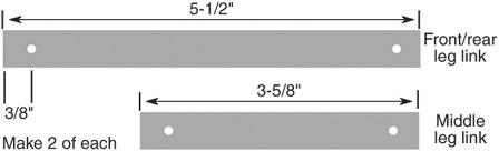
Figure 27-15 Linkages are made from 1/2″ brass strips, cut to length. The holes on either end are 1/8″. Make two of each length.
BUILD THE FRONT/REAR LEG ASSEMBLY
Prepare the left front/rear leg assembly using one rear leg and one front leg, plus one long linkage strip. Use 4-40 × 3/4″ machine screws, nylon spacers, and 4-40 locking nuts, as shown in Figure 27-16. Be sure not to overtighten the locking nuts. Repeat for the right front/rear leg assembly. Make this one in mirror image to the first.
BUILD THE MIDDLE LEG ASSEMBLY
Prepare the middle leg assembly by attaching the legs as shown in Figure 27-17. Use the middle spar, large round servo hub, short linkage strips, and fasteners as noted. You will need to drill out two of the holes in the servo hub to accommodate the screws. The other end of the linkages connects to the large servo hub. Drill out two holes at the 5 and 7 o’clock positions on the hub, as shown.
ASSEMBLE TO COMPLETE THE HEX3BOT
Remember the note about the locking nuts. The nuts should not be overtightened on their screws, or the robot may have difficulty in moving. Use a screwdriver and wrench to tighten the nuts so that they just begin to impede free movement. Then back off about 1/8 to 1/4 turn.
1. Begin with the servo that operates the middle legs. Attach the servo mount to the underside of the base using a pair of 3/8″ × 3/8″ miniature L brackets and 4-40 × 7/16″ machine screws and 4-40 nuts.

Figure 27-16 Side view of the legs and linkages, showing the hardware for assembly. The locking nut should not be so tight that it prevents the linkage from moving freely.
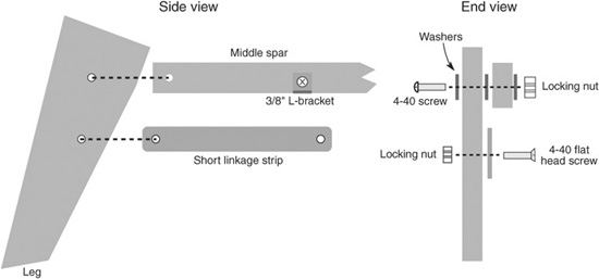
Figure 27-17 Construction detail of the middle leg assembly. Assemble both the right and the left middle legs, making sure they are in mirror image to one another.
2. Fasten the servo into the mount using two or four 4-40 × 1/2″ machine screws and 4-40 nuts. (When using only two screws, mount them on opposite corners of the servo.)
3. Mount two servos to the base using 4-40 × 1/2″ machine screws and nuts. The driveshaft of the motors should be closest to the rear of the base and should be on the side opposite the middle leg servo.
4. Attach the middle leg assembly to the top of the base using a pair of 3/8″ × 3/8″ miniature L brackets and 4-40 × 7/16″ machine screws and 4-40 nuts.
5. Connect each servo to your microcontroller (or similar circuit), and apply 1.5-millisecond pulses. This centers the servo to its middle, or neutral, position.
6. Attach the large round servo horn to the middle leg servo using the screw included.
7. Attach the left leg assembly to the left servo motor using the screw included with the servo.
8. Use a 6/32 × 1-1/2″ machine screw, washers, and 6/32 locking nut to attach the front left leg to the base. Place the two front leg spacer bars between the bottom of the leg piece and the base. Don’t forget the washers, as shown in Figure 27-18.
9. Repeat steps 7 and 8 for the right leg.
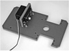
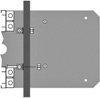
Refer to Figure 27-19 for an underside view of the completed Hex3Bot.
OPERATING THE HEX3BOT

See the RBB Online Support site (refer to Appendix A) for working microcontroller code for operating the Hex3Bot.
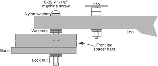
Figure 27-18 Assembly detail for attaching the front legs to the Hex3Bot base. Assemble both the right and the left front legs in the same fashion.
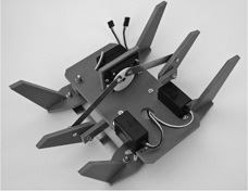
Figure 27-19 Under view of the completed Hex3Bot, showing how the middle legs are articulated using the servo.
Refer again to Figure 27-10 for the walking gait of the Hex3Bot. You need a microcontroller or serial servo controller to run the Hex3Bot’s servos. The walking sequence is straightforward:
1. Begin by rotating the middle leg servo so that one of the center legs (let’s say the left leg) is on the ground. Experiment to find a rotation angle that lifts the front/rear legs on the same side completely off the ground.
In the prototype Hex3Bot this angle was about 60° from center—the exact angle on your Hex3Bot may vary slightly depending on the particular measurements of the parts you built. You should expect some variance, and be ready to compensate for it in your program code.
2. Sweep the right front/rear legs back—toward the end with the servos—to push the robot forward. (It will actually move forward and turn to the left at the same time; this “waddling” is common with this form of hexabot).
3. Sweep the left front/rear legs forward to move them into position.

4. Rotate the middle leg servo so that the opposite (right) leg is on the ground and the right front/rear legs are lifted.
5. Sweep the left front/rear legs backward to propel the robot forward.
6. Sweep the right front/rear legs forward to move them into position.
7. Repeat these steps to continue moving. Optionally, you can add a speech synthesizer that says, “I’m walkin’ here, I’m walkin’ here!”
![]() To make the robot go in reverse, have the front/rear legs push in the opposite direction to that described previously.
To make the robot go in reverse, have the front/rear legs push in the opposite direction to that described previously.
![]() To make the robot turn, have only one side of the front/rear legs push.
To make the robot turn, have only one side of the front/rear legs push.
MOUNTING ELECTRONICS AND ACCESSORIES
There’s very little room on the top of the Hex3Bot for mounting batteries or electronics. To make space you’ll probably want to add a second deck, separating the deck with the base using standoffs or risers of some type or another. The standoffs should be at least 1-1/4″ long, in order to clear the mechanical movement of the legs.
In lieu of standoffs you can construct your own risers using a suitably long machine screw, some aquarium tubing, and a couple of nuts. Start by drilling matching holes in the Hex3Bot base and the second deck. For whatever riser length you want, add 3/4″ to accommodate the thickness of the base and deck, plus extra for securing a nut on top. In the case of a 1-3/4″ riser, select a 2-1/2″ screw, and cut the aquarium tubing to 1-3/4″.

Creating X-Y Servo Joints
With two servos (any size) and some basic parts, you can construct an articulated X-Y joint for use in multilegged robots, as well as servo turrets, gripper arms and wrists, and a variety of other mechanisms.
There are literally hundreds of ways to construct an X-Y joint using R/C servos. The one outlined here (maybe it’s #113, who knows?) is designed to be easy to construct using ordinary shop tools. It lacks some features such as supporting shafts on the side opposite the servo, which is useful when lifting heavier weight.
But given the typical robotic application, you’ll probably find this method more than adequate. (Of course, feel free to modify the design to incorporate any improvements you see fit. A couple of suggestions follow the how-to construction guide.
CUTTING THE PARTS
The sizing dimensions that follow assume you’re using standard-size servos. If you’re using larger or smaller servos, you’ll want to adjust the dimensions accordingly.
Using 6mm expanded PVC sheet or 1/4″ aircraft plywood, begin by cutting a strip measuring 2-1/2″ × 6-1/2″. This is enough to construct a pair of X-Y joints. If you need six pairs—you’re building a six-legged hexapod, for example—cut three of these strips.
As shown in Figure 27-20, next cut up the strip into four 1-1/2″ segments. Depending on the kerf width of your saw, the last segment may be wider than 1-1/2″; just cut it to the proper size. You will end up with:
![]() Two servo mounts. You’ll mount the servos to these.
Two servo mounts. You’ll mount the servos to these.
![]() Two solid plates. You’ll mount servo horns to these.
Two solid plates. You’ll mount servo horns to these.

Figure 27-20 Cutting guide for making the X-Y joint bracket pieces. Use a piece of 1/4″-thick wood or plastic that’s 2-1/2″ wide, and cut into 1-1/2″ slices.
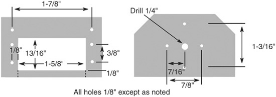
Figure 27-21 Final cutting and drilling guide for the X-Y joint bracket and solid plate. Cut on the dotted lines if making an enclosed rectangle proves difficult. If this is done, be sure to always mount the servo using all four screws.
Finally, on the two solid plates, chamfer (lop off) about 1/2″ on two corners, as shown. You can cut the corners off or grind them down if you have a power sander.
DRILLING THE PARTS
Using the drill patterns in Figure 27-21, drill the mounting holes in the plates and servo mounts. Important! The dimensions on the plates indicate candidate holes for matching with the servo horns you’re using. Different brands (e.g., Hitec and Futaba) have horns with different hole spacing around their circumference. You need only drill two holes opposite one another to match two of the holes in the servo horn.
All holes are 1/8″, except the hole in the center of the solid plate, which is 1/4″.
![]()
Printable drill patterns are available at the RBB Online Support site; see Appendix A for details. The patterns are in PDF format. Open the PDF and print out the pattern on regular paper. Cut the pattern pieces to size, then tape or lightly glue (use a glue stick) the pattern onto the wood or plastic pieces. Also on the RBB Online Support site are links to precut parts for building the X-Y joints detailed here.
Exercise care when drilling the four servo mounting holes. These need to be accurately placed.
CUTTING THE SERVO POCKET
Also on the drill pattern is a cutout guide for the servo. Using a coping saw with a general woodworking blade, carefully cut out the pocket for the servo, being careful not to take away too much material close to the mounting holes. You may wish to cut away too little, then come back with some rough sandpaper or a woodworking file and remove any extra so your servo will fit.
CONSTRUCTING THE X-Y JOINT
Refer to Figure 27-22 as you follow these steps to construct an X-Y joint. You will need two servos: one that mounts from the body (or some other part of your robot) and connects to the solid plate and the other that attaches to the servo mount. In addition to the servos, you need the following hardware for each X-Y joint:
![]() Six 4-40 × 1/2″ machine screws and nuts
Six 4-40 × 1/2″ machine screws and nuts
![]() Two #4 × 1/2″ wood screws
Two #4 × 1/2″ wood screws
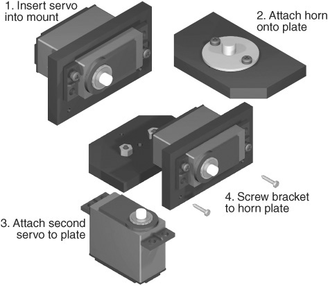
Figure 27-22 Basic assembly steps for constructing a generic X-Y joint with servos.

Figure 27-23 Complete X-Y joint, with servos.
1. Using 4-40 × 1/2″ machine screws and nuts, secure a servo into the servo mount. Use four machine screws for each servo.
2. Center the servo shaft to its midpoint. (You can temporarily mount a long-arm-style horn to the servo so that you can turn the servo shaft. Rotate the shaft slowly so that the internal gears are not damaged.)
3. Using 4-40 × 1/2″ machine screws and nuts, attach a disc-shaped servo horn onto a solid plate. You’ll probably need to drill out the hole on the servo horn in order to pass the screw through.
4. Dry-fit the edge of the solid plate without the chamfered corners against the two holes of the servo mount. Use a pencil or small nail to mark the position of the holes in the edge of the plate.
5. Using a center punch or nail set, create a shallow hole at the marks you scribed in step 4. Be sure the hole is in the middle of the thickness of the material. Be careful to avoid cracking off any of the material. You just need a light, shallow hole as a screw starter.
6. Attach the servo from your robot body (or arm, wrist, or whatever) to the servo horn you mounted in step 3. Insert the horn retaining screw (it comes with the servo) through the plate and into the servo output shaft. Do not overtighten.
7. Complete the X-Y joint by using the two 4-40 wood screws to secure the servo mount to the solid plate.

Figure 27-23 shows the completed X-Y joint.
USING AS A LEG JOINT
You can create a two-axis leg joint for a walking robot by mounting a servo from the underside (or topside) of your robot chassis and connecting the servo to the horn on the solid plate. See the section “Build a 12-Servo Hexapod” later in this chapter that uses these joints for legs.

Figure 27-24 Completed Hex12Bot, a hexapod robot with six individually manipulated legs. Each leg uses two servos, and therefore has 2 DOF.
USING AS A SENSOR TURRET
Turrets use motors to scan a sensor, or a group of sensors, back and forth. A single turret made with a standard R/C servo can provide near-180° coverage, sweeping back and forth looking for objects nearby and far. An X-Y joint allows you to sweep the sensor(s) horizontally, as well as tilt up and down. Mount a servo pointing upward on the robot chassis, and attach it to the horn on the solid plate. This provides the side-to-side motion of the turret.
Then attach a bracket of your own design to the other servo. This provides the up-and-down tilt motion. Sensors tend to be very lightweight, so they don’t need a heavy-duty turret structure. That saves on expense and weight.
USING AS PART OF A WRIST
By stringing X and Y segments together you can create a 3-DOF robotic wrist, similar to the joints of the human wrist and forearm, which can be used with a variety of grippers. See Chapter 29 for ideas on making robotic grippers.
Bonus Project: Build a 12-Servo Hexapod
Using the X-Y joints described in the previous section you can construct a hexapod with 2-DOF legs. The robot uses 12 servos, 2 per leg. Besides the X-Y joints already discussed, and the servos (of course), you need only six simple leg pieces and a base to mount everything on.
Figure 27-24 shows a completed 12-servo hexapod, the Hex12Bot, constructed with six X-Y joints. The robot measures 11-1/2″ by 7″, and stands over 6″. Full construction plans, with cutting and drilling templates, programming examples, and parts lists and sources, is provided as a free bonus project on the RBB Online Support site.