
Chapter 28
Experimenting with Robotic Arms
Robots without arms can’t “reach out and touch someone.” Arms extend the reach of robots and make them more like humans. For all the extra capabilities arms provide a robot, it’s interesting that they aren’t difficult to build. Your arm designs can be used for factory-style, stationary “pick-and-place” robots, or they can be attached to a mobile robot as an appendage.
This chapter deals with the concept and design theory of robotic arms. Incidentally, when we speak of arms, we will usually mean just the arm mechanism minus the hand (also called the gripper). Chapter 29, “Experimenting with Robotic Grippers,” talks about how to construct robotic hands and how you can add them to arms to make a complete, functioning appendage.
The Human Arm
Take a close look at your own arms for a moment. You’ll quickly notice several important points. First, your arms are amazingly adept mechanisms, no doubt about it. Each arm has two major joints: the shoulder and the elbow (the wrist, as far as robotics is concerned, is usually considered part of the gripper mechanism). Your shoulder can move in two planes, both up and down and back and forth. The elbow joint is capable of moving in two planes as well: back and forth and up and down.
The joints in your arm, and your ability to move them, are called degrees of freedom (DOF). Your shoulder provides 2 DOF in itself: shoulder rotation and shoulder flexion/extension (shoulder flexion is motion upward to the front; shoulder extension is motion downward to the rear). The elbow joint adds a third and fourth degree of freedom: elbow flexion/extension and elbow rotation.
Robotic arms also have degrees of freedom. But instead of muscles, tendons, ball-and-socket joints, and bones, robot arms are made from metal, plastic, wood, motors, solenoids, gears, pulleys, and a variety of other mechanical components. Some robot arms provide but 1 DOF; others provide 3, 4, and even 5 separate DOF.
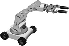
Figure 28-1 Robotic arm with three joints that each provide a degree of freedom.
Degrees of Freedom in a Typical Robotic Arm
Human anatomy offers an inexact comparison with robotic arm systems. Our bone and muscle structure provides movement in a way that is seldom duplicated in robot arms. For example, out of simplicity, most robotic arms don’t use a ball joint for the shoulder. In the human arm, this joint provides multiple degrees of freedom. In the robot version, shoulder motion is duplicated with two and sometimes three separate joints.
Figure 28-1 shows a representative robotic arm—it happens to be attached to a mobile base, which provides yet an additional degree of freedom, though many robot arms are stationary. The arm provides 3 degrees of freedom; additional freedoms are provided by the “wrist” and gripper.
![]() DOF #1 is rotation of the arm at its base. The base may rotate up to 360°, depending on design, though it’s more common to limit rotation to about 180°. This represents the mechanical extents of the typical R/C servo, which is often used to move the joints in a low-cost robotic arm.
DOF #1 is rotation of the arm at its base. The base may rotate up to 360°, depending on design, though it’s more common to limit rotation to about 180°. This represents the mechanical extents of the typical R/C servo, which is often used to move the joints in a low-cost robotic arm.
![]() DOF #2 and DOF #3 are essentially the shoulder and elbow joints, respectively. Together they allow the arm to lift and lower, and to position its gripper at the height and distance to grasp an object in front of it.
DOF #2 and DOF #3 are essentially the shoulder and elbow joints, respectively. Together they allow the arm to lift and lower, and to position its gripper at the height and distance to grasp an object in front of it.
As noted, the wrist mechanism of this arm adds 3 DOF of its own. These include two joints that form the wrist: it moves the gripper up and down and rotates it to position the gripper fingers to best grasp the object. The third DOF is the finger mechanism.
All the joints of the arm, including those in the gripper section, work in tandem to locate, grasp, and move objects. By pitching the shoulder, elbow, and wrist joints forward, the arm can reach down and pick up something on the ground.
Arm Types
Robot arms are classified by the shape of the area that the end of the arm (where the grip-per is) can reach. This accessible area is called the work envelope. For simplicity’s sake, the work envelope does not take into consideration motion by the robot’s body, just the arm mechanics.
The human arm has a nearly spherical work envelope. We can reach just about anything, as long as it is within arm’s length, within the inside of about three-quarters of a sphere. Imagine being inside a hollowed-out orange. You stand by one edge. When you reach out, you can touch the inside walls of about three-quarters of the orange peel.
In a robot, such a robot arm would be said to have revolute coordinates. The three other main robot arm designs are polar coordinate, cylindrical coordinate, and cartesian coordinate. You’ll note that there are 3 DOF in all four basic types of arm designs. Let’s take a closer look at each one.
REVOLUTE COORDINATE
Revolute coordinate arms, such as the one depicted in Figure 28-2, are modeled after the human arm, so they have many of the same capabilities. The typical robotic design is somewhat different, however, because of the complexity of the human shoulder joint.
The shoulder joint of the robotic arm is really two different mechanisms. Shoulder rotation is accomplished by spinning the arm at its base, almost as if the arm were mounted on a record player turntable. Shoulder flexion and extension are accomplished by tilting the upper arm member backward and forward. Elbow flexion/extension works just as it does in the human arm. It moves the forearm up and down. Revolute coordinate arms are a favorite design choice for hobby robots. They provide a great deal of flexibility, and, besides, they actually look like arms. See later in this chapter for details on how to construct a revolute coordinate arm.
POLAR COORDINATE
The work envelope of the polar coordinate arm is the shape of a half sphere. Next to the revolute coordinate design, polar coordinate arms are the most flexible in terms of the ability to grasp a variety of objects scattered about the robot. Figure 28-3 shows a polar coordinate arm and its various degrees of freedom.

Figure 28-2 Revolute coordinate arm. This is among the most common of arm designs for robotics.
A turntable rotates the entire arm, just as it does in a revolute coordinate arm. This function is akin to shoulder rotation. The polar coordinate arm lacks a means for flexing or bending its shoulder, however. The second degree of freedom is the elbow joint, which moves the forearm up and down. The third degree of freedom is accomplished by varying the reach of the forearm. An “inner” forearm extends or retracts to bring the gripper closer to or farther away from the robot. Without the inner forearm, the arm would only be able to grasp objects laid out in a finite two-dimensional circle in front of it.
The polar coordinate arm is often used in factory robots and finds its greatest application as a stationary device. It can also be mounted to a mobile robot for increased flexibility.
CYLINDRICAL COORDINATE
The cylindrical coordinate arm looks a little like a robotic forklift. Its work envelope resembles a thick cylinder, hence its name. Shoulder rotation is accomplished by a revolving base, as in revolute and polar coordinate arms.
The forearm is attached to an elevator-like lift mechanism, as depicted in Figure 28-4. The forearm moves up and down this column to grasp objects at various heights. To allow the arm to reach objects in three-dimensional space, the forearm is outfitted with an extension mechanism, similar to the one found in a polar coordinate arm.
CARTESIAN COORDINATE
The work envelope of a cartesian coordinate arm (Figure 28-5) resembles a box. It is the arm most unlike the human arm and that least resembles the other three arm types. It has no rotating parts. The base consists of a conveyer belt-like track. The track moves the elevator column (like the one in a cylindrical coordinate arm) back and forth. The forearm moves up and down the column and has an inner arm that extends the reach closer to or farther away from the robot.
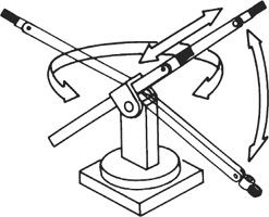
Figure 28-3 Polar coordinate arms are typical in manufacturing and industrial environments.

Figure 28-4 A cylindrical coordinate arm. It works like a forklift and can rotate on its base.

Figure 28-5 A cartesian coordinate arm.
Actuation Techniques
There are three general ways to move the joints in a robot arm: electrical, hydraulic, and pneumatic. For small robots, electrical actuation is the method of choice; it’s the least expensive and the easiest to implement. I’ll briefly describe the other two for the sake of completeness.
ELECTRICAL ACTUATION
Electrical actuation is done with motors, solenoids, and other electromechanical devices. It is the most common and easiest arm type to implement. The motors for elbow flexion/extension, as well as the motors for the gripper mechanism, can be placed in or near the base. Cables, chains, or belts connect the motors to the joints they serve.
Electrical actuation doesn’t always have to be via an electromechanical device such as a motor or solenoid. Other types of electrically induced actuation are possible using a variety of technologies. One of particular interest to hobby robot builders is shape memory alloy, or SMA, as discussed in Chapter 25, “Robot Movement with Shape Memory Alloy.” When electrical current is applied to the wire, it contracts.
HYDRAULIC ACTUATION
Hydraulic actuation uses oil-reservoir pressure cylinders, similar to the kind used in earthmoving equipment and automobile brake systems. The fluid is noncorrosive and inhibits rust: both are the immediate ruin of any hydraulic system. Though water can be used in a hydraulic system, if the parts are made of metal they will no doubt eventually suffer from rust, corrosion, or damage by water deposits. For a simple homebrew robot, however, a water-based hydraulic system using plastic parts is a viable alternative.
PNEUMATIC ACTUATION
Pneumatic actuation is similar to hydraulic, except that pressurized air is used instead of oil or fluid (the air often has a small amount of oil mixed in it for lubrication purposes). Both hydraulic and pneumatic systems provide greater power than electrical actuation, but they are more difficult to use. In addition to the actuation cylinders themselves, a pump is required to pressurize the air or oil, and valves are used to control the retraction or extension of the cylinders. For the best results, you need a holding tank to stabilize the pressurization.
Build a Robotic Wrist
Sometimes a whole arm isn’t required. All the bot really needs is a hand (gripper) on the end of a wrist-like mechanism that provides basic movement. The human wrist has 3 degrees of freedom: it can twist (rotate) on the forearm, it can bend up and down, and it can rock from side to side. You can add some or all of these degrees of freedom to a robotic hand.
You can create a basic 3-DOF wrist using the same X and Y components described in Chapter 27, “Build Robots with Legs”; see the section “Building X-Y Servo Joints.” Plans are provided for making compact parts for creating X-Y (pan/tilt, up-down/left-right) joints. By stringing together a sequence of these joints you can build a compact wrist that provides a remarkable amount of dexterity.

You can attach a variety of grippers to the wrist mechanism described here. See Chapter 29, “Experimenting with Robotic Grippers,” for some ideas and hands-on examples. Look especially at the easy-to-build gripper described in “Tool Clamp Gripper” in Chapter 29.
Parts you’ll need:
![]()
![]() X-Y pieces cut to size, according to the plans in Chapter 27. (See step 1, below.)
X-Y pieces cut to size, according to the plans in Chapter 27. (See step 1, below.)
![]() 16 4-40 × 1/2″ machine screws and nuts
16 4-40 × 1/2″ machine screws and nuts
![]() 4 #6 × 3/4″ wood screws
4 #6 × 3/4″ wood screws
![]()
1. Begin by cutting two pairs of X and Y pieces, as described in Chapter 27. To complete the wrist you’ll need to make one more servo bracket. You’ll end up with a total of five pieces: three servo brackets and two solid plates.
![]()
2. Using 4-40 × 1/2″ machine screws and nuts, secure each of the three servos onto servo mounts. Observe the orientation of the servo output shaft, along with the remaining two mounting holes of the mount. When viewed from the front, the shaft should be on the right and the two mounting holes should be on the bottom. When finished, you will have three servos in three mounts.

3. Using 4-40 × 1/2″ machine screws and nuts, attach a disc-shaped servo horn on a solid plate. Repeat for the second plate. When finished, you will have two servo horns on two plates.
![]()
4. Take one mounted servo and orient as shown (holes facing the top). Center the servo shaft to its midpoint. (You can temporarily mount a long-arm-style horn to the servo so that you can turn the servo shaft. Rotate the shaft slowly so that the internal gears are not damaged.) Note the orientation of the servo horn mount. The chamfered side should be on the left. Insert the horn retaining screw (it comes with the servo), through the horn mount, and into the servo output shaft. Do not overtighten. This is the wrist rotator.
![]()
5. Repeat step 4 (including centering the servo), except orient the servo so that the holes in the mount are on the bottom, rather than the top. Attach the solid plate so that the chamfered side faces bottom. This is the wrist flexor/extender.
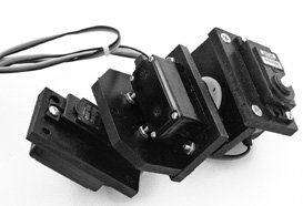
Figure 28-6 The completed wrist mechanism provides 3 degrees of freedom. It can be constructed using ordinary plastic or wood parts, and three R/C servo motors.

6. Attach the wrist rotator and the wrist flexor/extender subassemblies using two #6 × 3/4″ self-tapping screws. The screws are flat-head and should be tightened so that they are fairly flush with the surface of the mount.
![]()
The completed wrist is shown in Figure 28-6. When controlling the servos via a microcontroller or other means, be careful to limit the movement to the mechanical extents of the pieces. For the most part, wrists don’t have massive extents of movement—a little goes a long way.
Build a Functional Revolute Coordinate Arm
You can build your own revolute coordinate robotic arm with about $20 in parts—not including servo motors. The size of the arm is scalable; the prototype shown in Figure 28-7 stands about 8″ tall and has a reach (without gripper) of over 9-1/2″. It provides 4 degrees of freedom, including a rotating base and shoulder, elbow, and wrist joints.
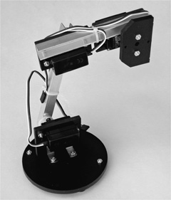
Figure 28-7 Completed robotic revolute coordinate arm. Attach the arm to a base or robot and add a gripper mechanism.
You will need four standard-size R/C servo motors. For added strength, select servos with a torque of no less than 45 oz-in; 65 to 85 oz-in is preferable. On most servos, the higher the torque, the slower the servo turns, so bear this in mind when selecting the motors for your arm.
To complete the arm, you’ll need:
![]() 1 12″ length of 3/8″ U-channel extruded aluminum
1 12″ length of 3/8″ U-channel extruded aluminum
![]() 1 3″ ball bearing turntable
1 3″ ball bearing turntable
![]() 1 small piece (about 12″ × 8″) 1/4″ aircraft-grade plywood or PVC plastic
1 small piece (about 12″ × 8″) 1/4″ aircraft-grade plywood or PVC plastic
![]() 1 pair of small 3/4″ corner angle brackets
1 pair of small 3/4″ corner angle brackets
![]() Small assortment of 4-40 machine screws and nuts
Small assortment of 4-40 machine screws and nuts
MAKE THE SERVO MOUNTS
The robotic arm uses two types of servo mounts and one general-purpose (and optional) solid plate for attaching to the shaft of the servo. The smaller mount and plate are described in the “Building X-Y Servo Joints” section of Chapter 27, “Building Robots with Legs.” You need two small mounts and one solid plate. You also need one slightly larger version of the servo mount, shown in Figure 28-8. It’s virtually identical to the mount detailed in Chapter 27, except the top flange is larger and the spacing for the two holes is different. You can construct these parts with 1/4″ aircraft-grade plywood or PVC plastic.
The spacing of the two holes in the top flange of the larger mount depend on the horns that come with your servos. The dimensions shown are for the large circular horn that comes with most Futaba and Futaba-style servos. If you use a different servo and horn, the hole spacing may be slightly different; adjust the spacing of the holes in the top flange accordingly.
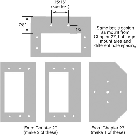
Figure 28-8 Cutting and layout guides for the servo mounts used in the revolute coordinate arm. Basic construction of the mounts is detailed in Chapter 27.
BUILD THE BASE
The base of the arm consists of a 3″ ball bearing turntable (“lazy Susan”) mounted on 4-1/2″-diameter round plastic, which serves as a bottom plate (this plate can be square if that’s easier for you to cut). You can get this size turntable at better stocked hardware stores and home improvement outlets, or via mail order. Search for 3″ lazy susan—I found mine for under $2 sold through Amazon.

1. Begin by drilling four holes to mount the turntable. Use the turntable itself to mark the holes in the center of the base. Once marked, drill the holes with a 1/8″ bit. Don’t mount the turntable just yet.
2. Using the largest horn that comes with your servos, find two holes opposite one another on the horn that are about 3/4″ to 1-1/4″ apart. Use a 1/8″ bit to drill these out.

3. Place the horn in the center of the 4″ bottom plate. Insert two 4-40 × 1/2″ machine screws through the horn and plate.

4. On the other side of the bottom plate, thread the screws through a pair of 3/4″ metal corner angle brackets. Secure the screws with 4-40 nuts.
5. Flip the bottom plate over again and mount the turntable using at least two screws on opposite corners. To insert the screws you’ll need to spin the turntable so that all the flanges (top and bottom) are exposed.
These construction plans don’t include mounting the fourth servo under the bottom plate. I’m leaving that up to you, based on where you want to put your arm. You can mount the arm on top of a mobile robot (it should be at least 8″ to 10″ in size), or you can build a stationary arm that operates within a confined space.
MOUNT THE JOINT SERVOS
You need to attach three servos into their mounts. Two sizes of mounts are used, as mentioned in “Building the Servo Mounts”: two regular-size mounts and one with a larger flange. Secure the servos to their mounts using at least two screws, one on each corner of the motor. Each of the servos needs to be oriented a certain way within its mount. Refer to Figure 28-9 for a guide. When viewed from the front of the servo, the output shaft of the motor should be located as shown. Secure the servo within its mount using at least two 4-40 × 1/2″ machine screws and nuts.
![]()
MOUNT SHOULDER SERVO TO BASE
Use the servo in the larger of the two mounts for the shoulder joint. This servo attaches to the two 3/4″ corner angle brackets using 4-40 × 1/2″ machine screws and nuts. The servo is oriented so that its mounting flange points toward the base. The backside of the motor is over the centerline of the base.

Figure 28-9 Orientation of the servo motors in the mounts. Attach the motors to the mounts with their output shafts oriented as shown.
CONSTRUCT UPPER ARM
Make an upper arm (the part of the arm between shoulder and elbow) from a 6″ length of 3/8″ aluminum U-channel. Cut with a hacksaw, and file down the ends to remove any burrs. Then:
1. Using the small round or double-arm horn that comes with your servos, use a 1/8″ bit to drill out two holes on opposite sides for mounting screws (see Figure 28-10). Once drilled out, mark three holes on each end of the upper arm: the two holes you just drilled and the center hole for the servo screw. Place the marks on the flat (“bottom”) of the U in the U-channel.
2. Use a 1/8″ bit to drill each of the marked holes (for best results, use a center punch to begin the hole—see Chapter 11, “Working with Metal,” for more tips and tricks).
3. Use a 1/4″ bit to drill out the center hole on each end of the upper arm. This makes the hole large enough for you to insert the servo horn screw.
4. Use 4-40 × 3/8″ or 4-40 × 1/2″ machine screws and nuts to secure the servo horns to the upper arm.
ATTACH UPPER ARM TO SHOULDER
Manually (and slowly) rotate the shoulder joint motor so that it is at its approximate center position. Use the screw supplied with the servo to attach the shoulder joint motor to the bottom of the upper arm.

Point the arm piece straight up when attaching the motor, so that the joint will rotate equally in both directions. Don’t overtighten the screw or else it might strip the output shaft of the servo.
ATTACH SERVOS TO FOREARM
Using 4-40 × 1/2″ machine screws and nuts, attach the two servos (the ones in the smaller mounts) to the forearm. Be sure to orient the servos so that one faces the “front” of the arm, and the other the back, as shown.
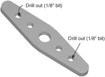
Figure 28-10 Drill out the holes in a servo horn for the base servo motor. For best results, pick holes in the horn that are about 1″ apart.
![]() The output shaft of the servo that faces the front (same side as the open part of the U-channel) should be on the right side.
The output shaft of the servo that faces the front (same side as the open part of the U-channel) should be on the right side.
![]()
![]() The output shaft of the servo that faces the back (flat part of the U-channel) should be on the left side. Refer to the completed pictures of the arm to see how the servos are oriented.
The output shaft of the servo that faces the back (flat part of the U-channel) should be on the left side. Refer to the completed pictures of the arm to see how the servos are oriented.
MOUNT UPPER ARM TO ELBOW
Manually (and slowly) rotate the shoulder joint motor so that it is at its approximate center position. Use the screw supplied with the servo to attach the elbow joint motor to the top of the upper arm. Don’t overtighten the screw or else it might strip the output shaft of the servo. As you did with the shoulder motor, mount the arm piece pointing straight up. That way the joint will rotate equally in both directions.
![]()
ATTACH WRIST
Attach the solid plate to the wrist joint motor. From this plate you can mount a gripper to the arm. (If your gripper already has a means to attach directly to the servo motor you can dispense with the solid plate.)
See Figure 28-11 for another view of the finished arm. Note that you’ll need to extend the length of the wires from at least the two servos mounted on the forearm in order to reach the control electronics. You can get servo extensions in 12″ lengths (and longer) at hobby stores specializing in radio control parts, and through online and mail-order outlets that sell servos.
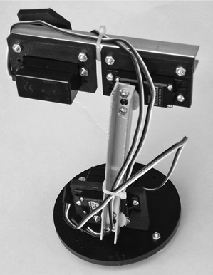
Figure 28-11 The reverse side of the revolute coordinate arm.
Build a Robotic Arm from a Kit
The revolute coordinate arm described in the preceding section is designed around simple components that can be constructed using ordinary tools and limited precision. If you want something more elaborate but don’t want to build it from scratch, you can choose from among a number of specialty robotic arm kits or use custom construction set parts
ARMS FROM ROBOTICS CONSTRUCTION SET PARTS
Think of these as Erector Sets for grown-ups—they’re parts of various shapes and sizes, with holes already drilled in them for attaching to R/C servos, motors, and other robotic components. One popular robotics construction set, the TETRIX Robotic Design System from online educational outlet Pitsco. Several sets are available, each with a different assortment of parts. You can also purchase individual parts as needed. Most construction sets are made with stamped aluminum, though they may also contain plastic pieces.
Even with the variety of parts that come in the typical robotics construction set, you’re not limited to using just those components. Unless there’s a restriction otherwise (you’re building a robot for a school competition, for example), you should feel free to add your own bits and pieces.
For example, you can combine a TETRIX U-channel with your own homebrew servo mounts to make two of the joints (shoulder, elbow) of a robot arm. The TETRIX U-channels measure 1-1/4″ in each of the three faces and are available in different lengths. I’ve used the 160mm (about 6-1/4″) channel in the upper arm mechanism shown in Figure 28-12.
ARMS FROM SPECIALTY KITS
Thanks to the popularity of amateur and educational robotics, there are plenty of specialty kits that are constructed just for the purpose of building a robot arm. Some are low-cost and meant for casual experimentation using manual switch control, but others, like the arm in Figure 28-13 from Lynxmotion, use R/C servo motors and microcontrollers to precisely position the arm components. Such arms may or may not come with a gripper; you can add one you made yourself or get a gripper kit and build it from premade parts.

Figure 28-12 Two servo motors, with homebrew mounts, attached to a TETRIX U-channel beam. Use a combination of ready-made and home-built parts for constructing arm arms.
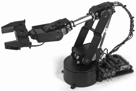
Figure 28-13 Robot arm kit, shown with control electronics and gripper. (Photo courtesy Lynxmotion.)
This particular arm has 4 degrees of freedom:
![]() Shoulder rotation, using a rotating base. This allows the arm to pick up objects in a circular arc of about 90° to each side.
Shoulder rotation, using a rotating base. This allows the arm to pick up objects in a circular arc of about 90° to each side.
![]() Shoulder flexion/extension, using a servo mounted near the base.
Shoulder flexion/extension, using a servo mounted near the base.
![]() Elbow flexion/extension, using a servo mounted off a yoke from the shoulder joint.
Elbow flexion/extension, using a servo mounted off a yoke from the shoulder joint.
![]() Wrist flexion/extension, using a servo mounted at the end of the forearm.
Wrist flexion/extension, using a servo mounted at the end of the forearm.
In almost all cases, arm kits are designed for use with standard-and mini-size R/C servos. The kits are available with and without servo motors, in case you already have some in your parts bin. If you supply your own servos, take note of any special requirements that are listed in the documentation for the arm. Some or all of the servos may need to have a minimum torque, for example.