
Chapter 24
Mounting Motors and Wheels
You’ve got two motors. You’ve got a robot body. What comes next isn’t always simple: you have to somehow mount the two motors onto the robot body, hopefully without making the thing look like a junkyard reject! Then there’s the problem of attaching the wheels.
DC motors and R/C servos each have their own means of mounting to a robot platform or frame. Some are easier than others. In this chapter you’ll learn ways to mount both common and not-so-common motors to robot frames and platforms. And you’ll learn about attaching wheels to those motors.
To round out the chapter, you’ll find helpful information about using standard drivetrain components—things like gears, chain, belts, and couplers.
Mounting DC Motors
There are no hard standards in the design of a DC motor. Depending on how the motor was meant to be used, it may be a snap to mount, or it could be cumbersome, requiring a hodgepodge of hardware.
![]() Generally speaking, motors meant for use in a variety of applications tend to have holes, brackets, or flanges that make mounting easier.
Generally speaking, motors meant for use in a variety of applications tend to have holes, brackets, or flanges that make mounting easier.
![]() Those motors engineered to work with just a specific product rely on the design of that product for secure mounting. There are no holes, no brackets, no flanges.
Those motors engineered to work with just a specific product rely on the design of that product for secure mounting. There are no holes, no brackets, no flanges.
Motors meant for robotics (or at least home-shop tinkering) are made with mounting in mind. These include the various Tamiya motor kits, all of which have flanges or other means for secure mounts. Solarbotics, Pololu, and several other robotics-centric online retailers import motors that have been especially selected because they offer mounting ease. Or else they provide their own mounting solutions, especially crafted for the motors they offer.
These and other motors like them are the easiest to work with, and if you’re just starting out in robotics, these should be the ones you choose. It’ll make your life much easier!
USING MOUNTING HOLES
Some motors have already-threaded holes on their faceplate (the side where the shaft comes out), like that in Figure 24-1. The threads may be imperial (inch) or metric. For imperial, 2-56 and 4-40 threads are the most common. For metric, you’ll often find holes tapped for 3mm or 4mm machine screws.
If you have a die-and-tap set, you can drill your own holes or retap existing holes. To do this you must disassemble the motor to remove the faceplate so you can drill new holes. Disassembly is required to prevent metal shavings (from drilling and tapping) from getting into the motor, which will render it inoperable.

It’s important that the machine screws you use don’t go too far into the motor, or else they may obstruct the rotating parts inside. If you don’t have the correct length of screw, you can either cut it to size or add washers on the outside. Washers don’t look as good, but they’re the easier solution.
If you’re mounting the motor perpendicular to the body of the robot, you may need to come up with a bracket to secure the motor to. More about brackets later in this chapter.
USING BUILT-IN FLANGES
Oh, happy joy—a motor with its own mounting flanges! It doesn’t get much better than this, so enjoy while you can. You know what you need to do here: just find some nuts and screws that fit, mark where the holes should go on your robot, and attach.
When mounting with flanges, I like to insert the head of the screw through the flange on the motor side (adding a flat washer if the head might come through the flange). A nut secures everything on the other side (Figure 24-2).
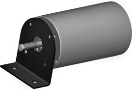
Figure 24-1 Motors with faceplate holes may use a flange for mounting. This method requires the proper size of machine screws; if the screws are too long, they’ll interfere with the moving parts inside the motor.
Figure 24-2 On motors with a mounting flange, insert the fastener from the flange side, when possible. In this way the exact length of the screw is not as critical, and you can use self-tapping screws that secure into the base material (wood, plastic, etc.).
USING BRACKETS
You need brackets if you must attach a vertically mounted motor to a horizontal surface. Metal brackets are common finds at any home improvement store. They tend to be a bit bulky, being made for general household applications. For smaller bots I prefer lightweight plastic brackets available at specialty online stores and miniature metal hardware available from the larger electronic parts outlets.
You can also fashion your own mounting brackets using metal or plastic. Cut the bracket to the size you need, and drill mounting holes. This technique works well when you are using servo motors for radio-controlled model cars and airplanes.
Brackets from Metal
You can make your own L-shaped metal brackets by bending a strip of aluminum, brass, or stainless steel metal. You can find these metal strips at many hobby stores. Aluminum and brass are easier to work with. They’re best for smaller motors. For larger and heavier motors, opt for stainless steel.
1. Cut the strip to the desired length—for example, make the strip slightly more than 2″ long for an L-shaped bracket that is 1″ × 1″. Each side of the L is a “leg” of the bracket, and it’s 1″ long.
2. Mark the midpoint of the bracket with a pencil. For that 2″ bracket, for instance, place a mark 1″ in.
3. With the metal strip held securely in a vise, drill at least one hole in each leg (see Figure 24-3). For larger brackets, drilling two holes is even better. Stay away from the midpoint mark you made in step 2.
4. For this next part, use a vise secured to your workbench. Put the strip into the vise so that the midpoint mark is just visible, and tighten the vise.
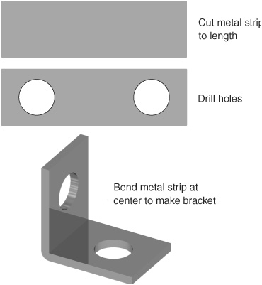
Figure 24-3 Make your own metal angle brackets by cutting strips of metal (copper, brass, aluminum) to length, then drilling holes. Bend at the middle to finish the bracket.
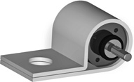
Figure 24-4 Pipe holders or straps (in metal or plastic) may be used to mount motors with round casings. Plastic straps provide more leeway in matching the size of the motor.
5. Use a hammer and a block of wood to fold over the exposed leg of the bracket. You want a neat 90° angle.
When making small brackets, drill the holes first, then cut the strip to length. You can make several bracket pieces at a time this way. If you need to make lots of brackets, draw the layout on a piece of paper and use it as a template for placing the holes and cuts.
Bracket Blocks from Wood and Plastic
You can make convenient block-style mounting brackets out of small pieces of 1/2″ or thicker wood or plastic. Start with a minimum 1.5″-long block. On one face of the block drill two holes close to the outside edges. On the other face drill at least one hole toward the center part of the block. You can then use the block as a type of L bracket.
For larger motors, use bigger and longer blocks. You may need two and even three mounting holes per face. Drill larger holes for bigger machine screws.
For plastic materials, visit your local neighborhood plastics retailer (check the Yellow Pages for one near you). Most have a discard bin in the front showroom with odds and ends. Look for small scraps of thick nylon, acetal resin (Delrin), and ABS plastic. The scrap is usually sold by the pound; enough material for a half dozen blocks should cost only a few dollars.
USING CLAMPS
If the motor lacks mounting holes, you can use clamps to hold it in place. U-bolts, available at the hardware store, are excellent solutions. Choose a U-bolt that is large enough to fit around the motor.
A technique that works with smaller motors is to use hold-down straps designed for EMT (electrical) conduit pipes. The straps, like the one in Figure 24-4, are available in various sizes, to hold down pipes of different diameters. These pipe straps are available at your local home improvement and hardware stores, in both metal and plastic. The plastic ones are easier to work with and lighter.
Mounting and Aligning Motors with Aluminum Channel
The same (but somewhat larger) aluminum channel used to construct robot frames can be used to mount and align DC motors. Find a channel that’s large enough inside for your motors to drop in place. A snug fit is best. This technique not only allows you to use a motor that otherwise lacks a convenient means of mounting, but guarantees that the two motors are precisely aligned with one another.
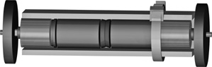
Figure 24-5 Motors in a differentially steered robot may be secured and aligned by placing them inside a strip of aluminum U-channel. The inside dimensions of the channel must be large enough to accommodate the girth of the motor. Use plastic cable-ties to hold the motors in place.
Cut the channel to length and, as shown in Figure 24-5, place the motors within the channel, end to end. If the motors protrude from the channel, you might be able to secure them in place using nothing more than a cable tie—for demonstration purposes, the illustration shows one tie, but you’ll probably need several to hold the motor in place. Cinch up the tie so that it firmly holds the motor.
Mounting R/C Servos
The world is quite a different place when working with R/C servos. By their nature, servos have mounting flanges; what’s more, servo sizes and mounting configurations are fairly standardized, giving you the option of premade mounting solutions if you don’t want to “roll your own.”
Whatever the method, servos should be securely mounted to the robot so the motors don’t fall off while the thing is in motion. Over the years, I’ve found “hard mounting”—gluing, screwing, or bolting—the servos onto the robot body to be the best overall solution. These techniques greatly reduce the frustration level of hobby robotics.
An exception to hard mounting is when creating so-called rapid prototypes, robots that test design principles and aren’t necessarily meant to last long. For these, things like Velcro, sticky tape, and tie-wraps are adequate for the job. Read more about this concept in Chapter 14, “Rapid Prototyping Methods.”
ATTACHING SERVOS WITH SCREWS
Unless you have a good reason not to, the best way to mount R/C servo motors to your robots is with screw fasteners. You have two kinds of screws to choose from:
![]() Self-tapping metal or wood screws don’t need a nut on the other end to hold things in place. Drill a small pilot hole to start, then insert the screw. The threads of the screw dig into the material and hold it into place.
Self-tapping metal or wood screws don’t need a nut on the other end to hold things in place. Drill a small pilot hole to start, then insert the screw. The threads of the screw dig into the material and hold it into place.
![]() Machine screws and nuts are ideal if you need to disassemble your creation and rebuild it, or use parts for something else.
Machine screws and nuts are ideal if you need to disassemble your creation and rebuild it, or use parts for something else.
Specialty Premade Servo Mounts
With the popularity of servos for robotics applications there’s no shortage of mounts for all types and sizes of servos. These are available from online sources and are not likely to be something you’ll find at a local store; see Appendix B, “Internet Parts Sources,” for a selected list of robotics specialty outlets, many of which offer servo mounts.
Making Your Own Servo Mounts
You can also construct your own servo mounting brackets using 1/8″-thick aluminum or plastic. A template is shown in Figure 24-6. (Note: The template is not to scale, so don’t trace it to make your mount. Use the dimensions to fashion your mount to the proper size. If you’d like a scale version of this mount, visit the RBB Online Support site; see Appendix A for the details.)
The first step in constructing your own servo mounting brackets is to cut and drill the aluminum or plastic following the template. Use a small hobby file to smooth off the edges and corners. Use 4-40 screws and nuts, or #4 self-tapping screws, to attach the servo mount to wood or plastic.
Servo “Tab” Mounting Brackets
For R/C servo motors of any size you can create simple mounts using a pair of “tab brackets. Start with a strip of 1/8″-thick aircraft plywood or plastic, and drill a pair of holes to match those on the flange of the servo motor. No closer than 3/8″ from these holes, drill one or two holes for a metal or plastic angle bracket.
After drilling, cut the strip near the pair of servo flange holes. Repeat this process again for the second bracket. Once you get the hang of it you can drill and cut a pair of servo brackets in just minutes. Figure 24-7 shows a pair of tab mounting brackets on a servo.
ATTACHING SERVOS WITH GLUE
Gluing is a quick and easy way to mount servos on most any robot body material, including heavy cardboard and plastic. For a permanent bond, use only a strong glue, such as two-part epoxy. For a somewhat less permanent construction, I prefer hot-melt glue because it doesn’t emit the fumes that epoxy does and it sets much faster.
When gluing, it is important that all surfaces are clean. Rough up the surfaces with a file or heavy-duty sandpaper for better adhesion. If you’re gluing servos to LEGO parts, apply a generous amount so the extra adequately fills between the “nubs.” LEGO plastic is hard and smooth, so be sure to rough it up first.
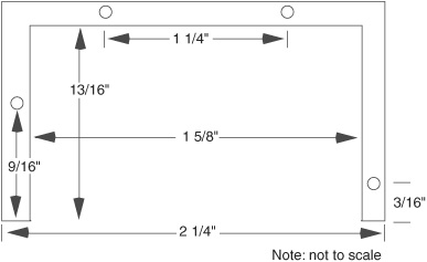
Figure 24-6 Make your own radio control servo mounts following this template (it’s not shown here to scale; be sure to draw it out on paper rather than trace it from the book). Cut the mount in wood, plastic, or metal, but make sure the material is thick enough to support the motor.
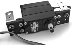
Figure 24-7 A pair of servo mounting tabs, shown with servo and 3/8″ metal angle brackets for securing to a robot base.
If you don’t need or want to permanently attach the servos, use less hot-melt glue or use a dab of ordinary white household glue. The bond is weaker, allowing you to more easily pry the servo off and reuse it for something else.
Mounting Drivetrain Components to Shafts
Drivetrain components are things like wheels, gears, sprockets, and other stuff that attach to your robot’s motors. Unless the parts are specifically designed for one another, connecting the shaft of the motor to drivetrain components is one of the more difficult tasks in building a robot.
Still, it’s not impossible, and robotics wouldn’t be as much fun without the occasional challenge. What follows are the most common methods used to connect a motor shaft to a wheel, gear, or other drivetrain component.
PRESSFITTING
For smaller drivechains, it’s not uncommon to use pressfit parts, where the shaft fits very tightly into the wheel or other component. Usually these are manufactured to fit this way, and the parts are assembled with heavy-duty hydraulic presses. You probably don’t have such a press in your garage; you’ll need to instead use a small hammer, a bit of spit for lubrication, and a few well-chosen curse words to knock the shaft into position.
SETSCREWS
A setscrew physically clamps the wheel or other part directly to the shaft. Setscrews are convenient and elegant, but they’re not common in amateur robotics because drivetrain parts that use them tend to be more expensive. You’re more likely to encounter setscrews when using small metal R/C parts like gears or locking collars (see the section that follows, on making your own shaft couplers).
Setscrews usually have hex socket heads, so you need a hex wrench in order to remove or tighten the screw. When purchasing R/C parts that use setscrews, the wrench is usually included.
PROPRIETARY INTERLOCK
Some motors and wheels (and other drivechain components) are made to go together. Good examples are the various DC gearbox motors and wheels from Tamiya. Many of the motors and wheels are designed for interchangeability. The wheels fit onto the motor shaft using nuts, pins, or other means.
SERVO HORNS
The output shaft of R/C servo motors has about two dozen tiny splined teeth carved around its circumference. These splines, and a metal screw that’s inserted into the bore of the shaft, are made to secure various styles and sizes of servo horns. Most servos come with at least one of these horns—typically a round or small, X-shaped jobbie.
Servo horns are made of plastic or metal (when of metal, it’s usually aluminum). You can drill holes for attaching things to the horns. This is one of the primary ways of securing wheels to a servo. You can also glue parts to the horns, though this works best when bonding plastic pieces to plastic horns. Hot-melt glue and epoxy are good choices.
ADHESIVES
Some motor shafts, wheels, and other drivetrain components can be bonded with an adhesive. This technique works best for plastic parts—don’t try to glue a metal shaft to a plastic wheel.
An example of using adhesives is to cement a LEGO axle into a non-LEGO plastic wheel. You can then use the axle/wheel combo in a LEGO creation. Drill out the hub of the wheel so it’s just smaller than the axle. Then gently tap the axle into the hole using a small hammer. You may set the axle in place using epoxy or household adhesive.
Mounting Wheels to DC Gear Motors
In the world of amateur robotics, you can now find motors that match the wheels made for them. Those are the easiest to use when building a bot, but there are many other options, too. With some effort, you can adapt a wheel to most any kind of motor, using either a direct connection—as described in this section—or a coupler, as detailed later in the chapter.
USING MATCHING MOTORS AND WHEELS
When I first started in robotics I used to spend an inordinate amount of time combing through various surplus catalogs, looking for motors and wheels that could go together. It wasn’t always easy to find matches. Today there are numerous specialty online robotics retailers that offer low-cost DC motors and wheels that are designed to complement one another.
And when I say low-cost, I do mean low-cost—it’s easy to find a motor-and-wheel set that’s priced under $10 each. You need two for a basic bot. Add some batteries, wire, some simple electronics (or even a microcontroller like the PICAXE), and you have a fully functional autonomous robot for under $30. Not bad.
BUILDING CUSTOM WHEELS
While matching motors and wheels are handy, selection isn’t always great. You may want a smaller or larger wheel than what’s offered, or you may not like the width of the rubber treads on the wheel. That’s when you need to come up with your own motor-to-wheel solution.
FYI
Be sure to also see the section “Using Rigid and Flexible Couplers” for more ideas on how to match wheels to motor shafts. Using couplers requires a bit more work than the methods outlined here, but sometimes you have no other choice.
Wheels with Setscrews
If your wheel already has a hub with a setscrew, you’re in business … assuming the wheel hub is the right size for the motor shaft. If it is, you’re ready to go. But if it’s not, there are a couple of things you can do to solve the problem:
![]() If the wheel hub is too small, drill it out to fit the shaft. Obviously, this works only if the hole you drill isn’t so large that it destroys the wheel hub.
If the wheel hub is too small, drill it out to fit the shaft. Obviously, this works only if the hole you drill isn’t so large that it destroys the wheel hub.
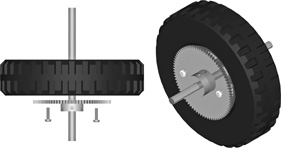
Figure 24-8 The concept behind using a metal or plastic gear as a flange for mounting a wheel to a motor shaft. Attach the face of the gear against the wheel hub; the gear provides a hub that can then be secured to the motor shaft.
![]() Use a reducing bushing, which is basically a short length of hollow tube. The inside of the bushing is sized to match the motor shaft; the outside, the wheel hub. You then carefully drill a hole through the bushing. Use a longer setscrew, if needed, to make it extend through the bushing and make contact against the shaft.
Use a reducing bushing, which is basically a short length of hollow tube. The inside of the bushing is sized to match the motor shaft; the outside, the wheel hub. You then carefully drill a hole through the bushing. Use a longer setscrew, if needed, to make it extend through the bushing and make contact against the shaft.
Using Flanges
But what if the wheel lacks a setscrew? One solution is to use a flange that does have a set-screw, and a hub with a properly sized bore that matches the motor shaft. You attach the flange to the wheel using fasteners, then mount the flange to the shaft.
A flange is anything smaller than the diameter of the wheel and that has a setscrew and hub compatible with the motor shaft you want to connect it to. Specially made flanges are available through Lynxmotion, Jameco, Servo City, and other online retailers. The flanges come in different bore sizes. Cost is modest.
A convenient ready-made flange is a surplus gear. Drill two or three holes through the face of the gear and matching holes into the wheel, being sure to keep the gear and wheel concentric. Mount the flat part of the gear against the wheel (see Figure 24-8), then attach the assembly to the motor shaft.
Mounting Wheels to R/C Servos
Servos reengineered for full rotation are most often used for robot locomotion and are outfitted with wheels. Since servos are best suited for small- to medium-size robots (under about 3 pounds), the wheels for the robot should ideally be between 2″ and 5″ in diameter, and lightweight.
WHEELS ENGINEERED FOR R/C SERVOS
By far the easiest way to attach wheels to servos is to use a wheel that’s specially engineered for the job. Many specialty robotics retailers sell wheels meant for use with the standard-size Hitec and Futaba servo.
Now for the bad news: Your choice of wheel diameters is pretty limited. You’ll find just a few sizes, with 2-1/2″ (give or take a few fractions of an inch) the most common. If you need a smaller or larger size, you can always make your own wheels, as detailed next.
Figure 24-9 Most any kind of wheel can be converted for use with an R/C servo by attaching a servo horn to the side of the wheel. If your servo didn’t come with an assortment of horns, you can purchase them separately.
Servos differ in the type of spline used on their output gear. The three most common spline types are noted simply by the servo manufacturer that popularized them: Hitec, Futaba, and Airtronics. If you are purchasing wheels for your servos, make sure the wheels use a matching hub spline. Wheels made for standard-size Futaba servos will also work on any other brand that uses the same Futaba-style spline, such as GWS.
MAKING YOUR OWN WHEELS FOR SERVOS
The general approach for attaching wheels to servos is to use the round servo horn that comes with the servo and secure it to the wheel using screws or glue (see Figure 24-9). The underside of the horn fits snugly over the output shaft of the servo. Here are some ideas:
Lightweight foam tires, popular for model airplanes, can be glued or screwed to the servo horn. Popular brands are Dave Brown and Du-Bro, and these can be found at most any well-stocked R/C hobby store. The tires are available in a variety of diameters, with the 2″, 2-1/2″, and 3″ diameters the best for small bots.
Large LEGO “balloon” tires have a recessed hub that exactly fits the small, round servo horn included with Hitec and many other servos. You can simply glue the horn into the rim of the tire.
A gear glued or screwed into the servo horn can be used as an ersatz wheel or as a gear that drives a wheel mounted on another shaft.
Homemade O-ring wheels can be constructed out of two plastic discs, cut to any diameter you like—though about 3-1/2″ is a practical maximum. The O-ring is the rubber tire of the wheel. At the center of the discs, mount a large, round servo horn, then fasten the pieces together using miniature machine screws and nuts.
Pulley horns look like three discs cemented together with a space in between. You can turn the pulley horn into a unique wheel by adding a pair of rubber O-rings as tire treads.
Urethane skateboard/inline roller-skate wheels make for incredibly “grippy” wheels for robots. The trick, if it can be called that, is to find metal or plastic discs that just fit into the hub of the wheel. Most skate and inline blade wheels use metric sizes, with a hub diameter of 22 mm. A 0.625″-diameter fender washer fits into the bore of the wheel but is (usually) large enough to stop against the ridge that’s molded into the center of the wheel. Hold all the pieces together with a 4-40 machine screw that goes from the outside of the wheel and directly into the servo motor output shaft.

Figure 24-10 Rotary motion can be converted to linear motion by using a pushrod linkage. As the servo rotates, the end of the linkage moves back and forth.
Attaching Mechanical Linkages to Servos
A key benefit of using R/C servos is the variety of ways you can connect stuff to them. In model airplane and car applications, servos are most often connected to a push/pull linkage (called a pushrod). As the servo rotates, the pushrod draws back and forth, like that in Figure 24-10.
You can use the exact same hardware designed for model cars and airplanes with your servo-equipped robots. Visit the neighborhood hobby store and scout for possible parts you can use. Look for pushrods and clevis ends.
CONTROLLING LINEAR MOVEMENT
So you can see how pushrods allow you to convert the rotation of a servo to linear movement. There are two key ways of controlling the amount of linear movement you get:
![]() Use a larger or smaller horn on the servo. The larger the horn, the larger the movement of the pushrod.
Use a larger or smaller horn on the servo. The larger the horn, the larger the movement of the pushrod.
![]() Use a specific pivot point for the pushrod, a mechanical constriction like an eyelet, channel, or hole that limits the movement of the pushrod to just back-and-forth motion. As shown in Figure 24-11, the closer the pivot is to the servo, the wider the movement pattern; conversely, the farther away from the servo, the narrower the pattern.
Use a specific pivot point for the pushrod, a mechanical constriction like an eyelet, channel, or hole that limits the movement of the pushrod to just back-and-forth motion. As shown in Figure 24-11, the closer the pivot is to the servo, the wider the movement pattern; conversely, the farther away from the servo, the narrower the pattern.
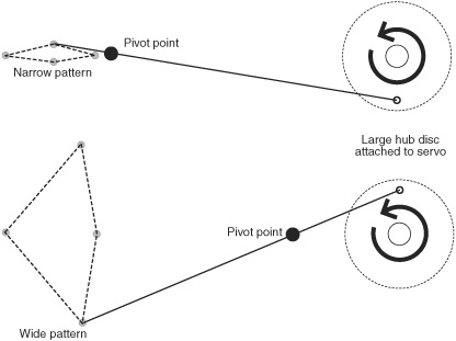
Figure 24-11 Control the angular displacement of the pushrod by changing the location of the pivot point, which is simply a mechanical conduit (small tube, hole, plastic grommet) that restricts side-to-side motion. Avoid placing the pivot point too close to either end of the pushrod.
There will always be some side-to-side motion in the linear movement. For this reason, it’s a good idea to design a bit of “slop” in the pushrod system, such as a loose clevis end on either end of the pushrod.
ADDING LUBRICATION
Parts that slide against each other should be kept lubricated, to prevent them from binding up. Use a thick grease, not oil. Grease for hobby R/C is available at any store that carries these parts. It comes in a small tube; you want the white or clear stuff. My favorite is white lithium grease.
Drivetrain Components for Robotics
Pushrod mechanical links are one form of drivetrain—get the power of a motor from one place to another. There are hundreds of drivetrain components you might use in your robot creations, but the following table summarizes the most commonly used. These drivetrain parts go between the motor and the wheel or other driven element, such as legs, tracks, or arm segments.
Gears
Gears are a principal component of drivechains and are primarily used in robotics to reduce the speed, and increase the torque, of the wheel drive motors. They are also used to share the power between several wheels or other components.

Because of the mechanical precision required to properly mesh gears, most amateur robot builders do not construct their own gear assemblies. More about gears later in the chapter.
Timing Belts
Timing belts are also called synchronization or toothed belts, and they can be used to make tracked robots, as well as substitute for more complex gear systems.

Widths range from 1/8″ to 5/8″, and lengths from just a few inches to several feet in diameter. Material is usually rubber. Belts are rated by the pitch between “nubs” or “cogs,” which are located on the inside of the belt. The cogs interface with matching rollers.
Endless Round Belts
Endless round belts are used to transfer low-torque motion. The belt looks like an overgrown O-ring and, in fact, is often manufactured in the same manner.

Grooved pulleys are used with round belts. The diameter of the pulleys can be altered to change torque and speed. Like timing belts, you can use round belts as the tire material on wheels and for unusual treads in a tracked robot.
Roller Chain
Roller chain is exactly the same kind used on bicycles, only in most robotics applications it’s smaller.

Roller chain is available in miniature sizes, down to 0.1227″ pitch (distance from link to link). More common is the #25 roller chain, which has a 0.250″ pitch. For reference, most bicycle chain is #50, or 0.50″ pitch. The chain engages a sprocket that has teeth of the same pitch.
Idler Wheels
Idler wheels (also called idler pulleys or idlers) take up slack in belt- and chain-driven mechanisms. The idler is placed along the length of the belt or chain and is positioned so that any slack is pulled away from the belt or chain loop. Not only does this allow more latitude in design, it also quiets the mechanism.

Couplers
Couplers come in two basic styles: rigid and flexible. They are used to directly connect two shafts together, so you don’t need a gear or belt to transfer the power. Couplers are common when connecting wheels and motors that aren’t otherwise designed for one another.

Bearings
Bearings are used to reduce the friction of a spinning component, such as a wheel or idler, around a shaft. There are lots of types of bearings, but ball bearings are the most common. The ball bearing is composed of two concentric rings; between each ring is a row of metal balls. The rings—and the ball bearings—are held in place by a flange.

Bushings
Bushings and bearings serve the same general purpose, except a bushing has no moving parts. (Note: Some people call these dry bearings.) The bushing is made of metal or plastic and is engineered to be self-lubricating. Bushings are used instead of bearings to reduce cost, size, and weight, and are adequate when friction between the moving parts can be kept relatively low.

Using Rigid and Flexible Couplers
Couplers are used to connect two drive shafts together end to end. A common application is to use a coupler to connect the drive shaft of a motor with the axle of a wheel. Couplers can be rigid or flexible.
Rigid couplers are best used when the torque of the motor is low, as it would be in a small tabletop robot. Conversely, flexible couplers are advised for higher-torque applications, as they are more forgiving of errors in alignment. Why is this? A rigid coupler may shear off or damage the motors or shafts when misaligned.
PURCHASING READY-MADE COUPLERS
There are many types of commercially available rigid and flexible couplers, and cost varies from a few dollars to well over $50, depending on materials and sizes. Common flexible couplers include helical, universal joint (similar to the U-joint in the driveshafts in older cars), and three-piece jaw.
The couplers attach to the shafts either with a press fit, by a clamping action, by setscrews, or by keyway. Press fit and clamp are common on smaller couplers for low-torque applications; setscrews and keyways are used on larger couplers.
Three-piece jaw couplers (Figure 24-12; see-through and partially disassembled), like those made by Lovejoy, consist of two metal or plastic pieces that fit over the shafts. These are the “jaws.” A third, rubberized piece, the spider, fits between the jaws and acts as a flexible cushion.
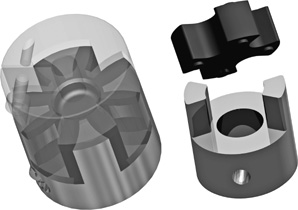
Figure 24-12 A three-piece jaw coupler uses two metal or plastic “jaws” that connect to the driveshafts and a softer (often rubber) inner piece that provides the flexibility.
One advantage of three-piece couplers is that because each piece of the jaw is sold separately, you can readily “mix and match” shaft sizes. For example, you can purchase one jaw for a 1/4″ shaft and another for a 3/8″ shaft. Both jaws must have the same outside diameter.
MAKING YOUR OWN RIGID COUPLERS
To save money, you can make your own rigid couplers using metal tubing, metal or plastic standoffs, or threaded couplers.
Couplers from Tubing
You can get brass, steel, and aluminum tubing of various diameters at hobby stores; larger aluminum tubing can be found at home improvement outlets. Most tubing is sold by its inner diameter—1/8″ tubing measures an eighth of an inch inside, for example. The thickness of the tubing determines its outside diameter. Get tubing that fits over the motor or wheel shaft you’re attaching to.
When matching up tubing, note its I.D. (inside diameter). Tubing at the hobby store is meant to fit into the next size larger, as in a folding telescope. You can use this feature to match one shaft diameter to another. Typical thickness of the tubing is between 0.014″ and 0.049″, though this varies somewhat by brand.
For lightweight robots with small motors, look at 1/8″ or 3/16″ I.D. If possible, bring your motor or wheel (or just the shaft) to the store with you so you can test the pieces for proper fit.
To use, cut the tubing to length. Use a tubing cutter instead of a saw. You can then secure the tubing to the shaft in several different ways, including the following:
![]() Crimp it on with an appropriately sized metal collar. The collar comes with a setscrew. Carefully tighten the setscrew over the tubing (see Figure 24-13). This type of metal collar is available at any R/C hobby store and often goes by the name Dura Collar. If you can’t find a collar just the right size for the tubing, you may need to select the next size smaller, then drill it out. The collar is typically plated brass, so it’s not as hard to drill as it may look.
Crimp it on with an appropriately sized metal collar. The collar comes with a setscrew. Carefully tighten the setscrew over the tubing (see Figure 24-13). This type of metal collar is available at any R/C hobby store and often goes by the name Dura Collar. If you can’t find a collar just the right size for the tubing, you may need to select the next size smaller, then drill it out. The collar is typically plated brass, so it’s not as hard to drill as it may look.
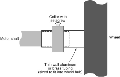
Figure 24-13 Thin tubing doesn’t have enough “bite” for a setscrew. But you can use a metal collar around the tubing to provide compression against a solid motor shaft. Tighten the setscrew in the collar for a solid fit.

Figure 24-14 Metal collars may be used on wheels with an outsized hub (the hub protrudes from the wheel, giving more surface area to the shaft). Place the collar around the hub of the wheel. The compression tightens the hub around the motor shaft.
![]() Use large wire crimper pliers to squeeze the tubing around the shaft. This works only for thin-walled tubing and when working with smaller motors that don’t develop a lot of torque.
Use large wire crimper pliers to squeeze the tubing around the shaft. This works only for thin-walled tubing and when working with smaller motors that don’t develop a lot of torque.
When using the crimp-on metal collar trick, you can help cinch up the fit by drilling a small (1/16″) hole in the tubing where the setscrew for the collar will go. This works well when using thicker-walled tubing. When assembling the collar over the tubing, carefully line up the hole with the setscrew, then tighten the screw.
Don’t forget that some wheels have outsized hubs, like the one in Figure 24-14. You may not even need to use tubing to make a coupler. Just attach the collar around the existing hub of the wheel, and tighten the set screw. With plastic wheels the hub will deform, cinching around the shaft for a fairly tight fit.
Couplings from Standoffs and Threaded Couplers
Commercially available rigid couplers often use setscrews to hold the coupler to the shaft. Thin-wall tubing is too thin for a setscrew. You need a thicker-walled coupler.
There are two ready-made sources of short metal and plastic begging to be turned into shaft couplers: standoffs and something called threaded couplers.
Standoffs are commonly used in electronics projects to keep two circuit boards or other pieces separate from one another. I regularly use metal and plastic standoffs to add additional “decks” to my robots. The decks are like tiers in a wedding cake. The standoffs are typically 1″ or longer and are made of nylon, steel, or aluminum. I like working with aluminum over steel, as aluminum is easier to drill and cut. You can get either the threaded or the nonthreaded kind, but the unthreaded kind is easier to work with.
Threaded couplers are just like standoffs but are almost always made of heavier steel. You get them at the local hardware or home improvement store. They come in thread sizes from 6-32 to 5/16″ and larger. The 6-32 thread size is about right for 1/8″ shafts.
To make shaft couplers, you should have a vise and a drill press in order to make accurate holes. You also need a tap set with drill bits. The bits are already correctly sized for the taps.
Nylon can’t hold a thread as well as aluminum or steel. If you go with a nylon standoff, use it only with shafts that have a flatted side to them. Round shafts require more pressure to keep them from turning, but this added pressure of the setscrew against the nylon just strips out the threads.
1. Secure the standoff or coupler into the vise. Make it nice and snug.
2. Use a center punch to mark where you will be drilling. You want two holes, no closer than about 1/4″ from the ends. The punch makes a mark in the plastic or metal that serves as a pilot for keeping the bit on track.
3. For metal standoffs and couplers, apply some light machine or cutting oil on the mark. Slowly drill the holes for the setscrews all the way through one side of the standoff or coupler. Don’t drill through to the other side unless you want to put setscrews on that side as well.
4. Turn the standoff or coupler on end and tighten in the vise. Change the drill bit to the size of the shaft you’re using. For example, if the shaft is 1/8″ in diameter, use a 1/8″ drill bit.
5. Drill halfway down the length of the standoff or coupler, then turn it upside down. Drill through the second half.
6. Now to tap the holes for the setscrews. Change the bit (if needed) to the correct size for the setscrew you wish to use. See Appendix C, “Mechanical Reference,” for a handy list of drill bits and tap sizes for making different kinds of holes.
7. Put a drop or two of machine or cutting oil into the holes you’ve drilled (metal standoff or coupler only), then carefully tap them to make threads. You can skip the cutting oil when tapping into plastic.
I’m not going to give a lot of detailed explanation about how to use taps to thread a hole, as this information is everywhere on the Internet. Do a quick Web search for phrases like how to drill and tap.
MAKING YOUR OWN FLEXIBLE COUPLERS
For many desktop robotics jobs, flexible plastic rubber tubing will work just dandy as a coupler. Select the rubber tubing so that it is just slightly smaller than the motor shaft and wheel axle you are using, and press it on for a good fit. If the motors develop too much torque for the press-fit to hold, use small worm-gear clamps to hold the tubing in place. You can get these worm-gear clamps at any hardware store.
See Figure 24-15 for one example. The wheel is held in place with a pillow block, which is merely a piece of wood, plastic, or metal with a hole in it that’s fastened to the base of the bot. Use a long machine screw as the wheel axle; hold the wheel-axle combo in the pillow block with a pair of nylon insert locking nuts, as shown. Plastic tubing is available at hardware and home improvement outlets, as well as many hobby stores and pet stores that sell fish aquarium supplies.

Figure 24-15 Flexible rubber tubing or hose may be used to connect a motor shaft to a wheel with its own axle. Shown here is an axle made with a machine screw, but any type of axle compatible with the inner diameter of the tubing will work. Use hose clamps around the tubing if the fit is too large.
Try to get tubing the same size or slightly smaller than the shaft diameter. Prior to fitting, you can put the tubing into hot water to soften and expand it. With the tubing still warm, slip it over the shaft. Wait for the tubing to cool, then do the twist test to see if it’ll work as a shaft coupling.
Tubing is sized in different ways—it is sometimes sold by its inside diameter (I.D.) and sometimes by the outside diameter (O.D.). Bring your parts into the store for a dry fit. Tubing sold by the foot is the most economical, as you can buy just short lengths at a time. You don’t need much.
Working with Different Shaft Types
Motor shafts come in several shapes and forms. A few of the more common ones are shown in Figure 24-16. Most motors use a simple round shaft; most secure to a gear or wheel hub using a tight friction fit. A flatted or “D” shaft is best when using a setscrew, as the tip of the screw can settle into the flat depression. Flatted shafts may also be used for friction fit. The “D” helps prevent the shaft from spinning inside the wheel or gear hub.
Some motors have threaded shafts. For example, several motors in the Tamiya educational motor lineup have a short male-threaded shaft end. Using locking nuts you can secure wheels and other components onto the end. R/C servo motors use a female-threaded shaft to secure a servo horn or other accessory to the motor. On servo motors, the shaft is also splined to help prevent slippage.

Figure 24-16 Common shaft types you will encounter: round, flatted, and threaded (both male and female). The flatted type is also called a D-shaft, because it resembles the letter D.
Other shaft types you may encounter include the hex and square, so called because of their hexagonal or square shape. They’re used with wheels, gears, and other parts that have matching-shaped hubs.
Everything You Always Wanted to Know about Gears
We’ve already discussed the fact that the normal running speed of motors is far too fast for most robotics applications. Locomotion systems need motors with running speeds of 75 to 200 RPM. Any faster than this, and the robot will skim too quickly across the floor. Arms, gripper mechanisms, and most other mechanical subsystems need even slower motors. The motor for positioning the shoulder joint of an arm needs to have a speed of less than 20 RPM; 5 to 10 RPM is even better.
There are two general ways to decrease motor speed significantly: build a bigger motor (impractical) or add gear reduction. Gear reduction is used in your car, on your bicycle, in the washing machine and dryer, and in countless other motor-operated mechanisms.
GEARS 101
Gears have two main applications:
![]() To transfer power or motion from one mechanism to another.
To transfer power or motion from one mechanism to another.
![]() To reduce or increase the speed of the motion between two linked mechanisms.
To reduce or increase the speed of the motion between two linked mechanisms.
The simplest gear systems use just two gears: a drive gear, and a driven (or output) gear. More sophisticated gear systems, referred to as gear trains, gearboxes, or transmissions, may contain several or even dozens of gears. Motors with attached gearboxes are said to be gearbox motors.
We use these gearbox motors a lot in robotics. R/C servos have their own gearbox built in, and most of the DC motors we use to power wheels and tracks of bots have a gearbox of some type. Though these already have a gearbox for speed reduction, there are many applications for adding external gears, such as making one motor drive two wheels at the same time.
GEARS ARE LEVERS IN THE ROUND
In a way, gears are round levers, and it may help to explain how gears function by first examining the basic mechanical lever.
Here goes: Place a lever on a fulcrum so that the majority of the lever is to one side. Push up on the long end, and the short side moves in proportion. Although you may move the lever several feet, the short end is moved only a few inches. But note that the force available on the short end is proportionately larger than the force applied on the long end.
Now back to gears. Attach a small gear to a large gear, as shown in Figure 24-17. The small gear is directly driven by a motor. For each revolution of the small gear, the large gear turns one half a revolution. Expressed another way, if the motor and small gear turn at 1000 RPM, the large gear turns at 500 RPM. The gear ratio is said to be 2:1.
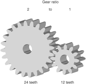
Figure 24-17 Two meshing gears, showing a 2:1 gear ratio. The gear on the left has twice the number of teeth as the gear on the right.
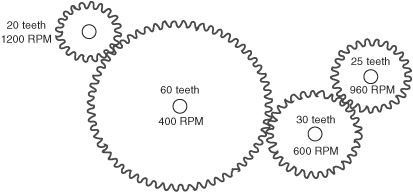
Figure 24-18 The number of gear teeth directly relates to speed.
As with a lever, another important thing happens: decreasing the speed of the motor also increases its torque. The power output is approximately twice the input. Some power is lost in the reduction process due to the friction of the gears. If the drive and driven gears are the same size, the rotation speed is neither increased nor decreased, and the torque is not affected (apart from small frictional losses). You can use same-size gears in robotics design to transfer motive power from one shaft to another.
ESTABLISHING GEAR REDUCTION
Gears are an old invention, going back to ancient Greece in about the third century BC. Today’s gears are much refined, though they’re still based on the old designs in which teeth from the two mating gears mesh with each other. Force is transferred from one gear to another.
Gears with the same size teeth are usually characterized not just by their physical size but also by the number of teeth around their circumference. In the example in Figure 24-17, the small gear contains 12 teeth, the large gear 24 teeth. And you can string together a number of gears one after the other, all with varying numbers of teeth (see Figure 24-18). Attach a tachometer to the hub of each gear, and you can measure its speed. You’ll discover the following two facts:
![]() The speed always decreases when going from a small to a large gear.
The speed always decreases when going from a small to a large gear.
![]() The speed always increases when going from a large to a small gear.
The speed always increases when going from a large to a small gear.
There are plenty of times when you need to reduce the speed of a motor from 5000 RPM to 50 RPM. That kind of speed reduction requires a reduction ratio of 100:1. To accomplish that with just two gears you would need, as an example, a drive gear that has 10 teeth and a driven gear that has 1000 teeth—quite impractical.
Instead, you reduce the speed of a motor using multiple gears, as in Figure 24-19. Here, the drive gear turns a larger “hub” gear, which in turn has a smaller gear permanently attached to its shaft. The small hub gear turns the driven gear to produce the final output speed, in this case 250 RPM. You can repeat this process over and over again until the output speed is but a tiny fraction of the input speed.

Figure 24-19 True speed reduction is accomplished by ganging gears together. The idea is to always go from fewer teeth to more teeth; with each step, the speed is reduced (and torque is increased).
There are many other ways to achieve large-ratio gear reductions, and this is just one of them. Other techniques include worm, planetary, and hypoid gears; you might find gearbox motors that use these techniques, but they tend to be more expensive.
VARIATIONS IN GEAR TEETH
All of the examples shown so far have been of spur gears, which are the most common. They’re used when the drive and driven shafts are parallel. Bevel gears have teeth on the surface of the circle rather than the edge. They are used to transmit power to perpendicular shafts. Miter gears serve a similar function but are designed so that no reduction takes place.
Spur, bevel, and miter gears are reversible—the gear train can be turned from either the drive or the driven end. Conversely, worm and leadscrew gears transmit power perpendicularly and are not usually reversible The lead screw resembles a threaded rod.
Rack gears are like spur gears unrolled into a flat rod. They are primarily intended to transmit rotational motion to linear motion.
COMMON GEAR SPECIFICATIONS
Here are some common gear specifications to keep you warm at night.
Pitch: The size of gear teeth is expressed as pitch, which is roughly calculated by counting the number of teeth on the gear and dividing it by the diameter of the gear. Common pitches are 12 (large), 24, 32, 48, and 64. Odd-size pitches exist, of course, as do metric sizes.
Pressure angle: The degree of slope of the face of each tooth is called the pressure angle. A common pressure angle is 20°, although some gears, particularly high-quality worms and racks, have a 14-1/2° pressure angle.
Tooth geometry: The orientation of the teeth on the gear can differ. The teeth on most spur gears is perpendicular to the edges of the gear. But the teeth can also be angled, in which case it is called a helical gear. There are a number of other unusual tooth geometries in use, including double-teeth and herringbone.
USING MOTORS WITH GEAR REDUCTION
It’s always easiest to use motors that already have a gear reduction box built onto them. When selecting gear motors, you’ll be most interested in the output speed of the gearbox, not the actual running speed of the DC motor itself. Note also that the running and stall torque of the motor will be greatly increased at the output of the gearbox.
When using motors without built-in gear reduction, you’ll need to add reduction boxes or make your own. Although it is possible to do this yourself, there are many pitfalls:
![]() Shaft diameters of motors and ready-made gearboxes may differ, so you must be sure that the motor and gearbox mate.
Shaft diameters of motors and ready-made gearboxes may differ, so you must be sure that the motor and gearbox mate.
![]() Separate gear reduction boxes are hard to find. Most must be cannibalized from salvage motors. Old AC motors are one source of surplus boxes.
Separate gear reduction boxes are hard to find. Most must be cannibalized from salvage motors. Old AC motors are one source of surplus boxes.
![]() Machining the gearbox requires precision, since even a small error can cause the gears to mesh improperly.
Machining the gearbox requires precision, since even a small error can cause the gears to mesh improperly.
WHERE TO FIND GEARS
Gears can be expensive, especially the metal ones that are machined from a piece of solid metal. Online sources like Boston Gear, Small Parts, W.M. Berg, and Stock Drive offer these and most any other gear imaginable, but at costs that make the average robot builder blanch.
As long as your requirements aren’t too unusual, you may be able to locate the gears you want from other products and sources.
![]() Hobby and specialty retailers. Next time you’re at a hobby store, look for replacement gear sets for servos and drive motors for R/C cars and airplanes. Some are plastic; others are metal (usually either aluminum or brass).
Hobby and specialty retailers. Next time you’re at a hobby store, look for replacement gear sets for servos and drive motors for R/C cars and airplanes. Some are plastic; others are metal (usually either aluminum or brass).
![]() Toy construction sets. Don’t laugh! Toys like LEGO, Erector, and Inventa come with gears you can use in your robotics projects. Most are on the large side and are made of plastic.
Toy construction sets. Don’t laugh! Toys like LEGO, Erector, and Inventa come with gears you can use in your robotics projects. Most are on the large side and are made of plastic.
![]() Surplus catalogs. New gears can be expensive; surplus gears can be quite affordable. You can often find new gears, plastic or metal, for about 10 cents on the dollar, compared to the cost of the same gear new. The only problem: Selection can be limited, and it can be hard to match gear sizes and pitches even when buying gears from the same outlet.
Surplus catalogs. New gears can be expensive; surplus gears can be quite affordable. You can often find new gears, plastic or metal, for about 10 cents on the dollar, compared to the cost of the same gear new. The only problem: Selection can be limited, and it can be hard to match gear sizes and pitches even when buying gears from the same outlet.
![]() Rechargeable electric screwdrivers. Inside are numerous gears, typically in a “planetary” configuration, used to produce their very high speed reductions. Before raiding the screwdriver for just the gears, consider using the motor, too.
Rechargeable electric screwdrivers. Inside are numerous gears, typically in a “planetary” configuration, used to produce their very high speed reductions. Before raiding the screwdriver for just the gears, consider using the motor, too.
![]() Hacked toys Discarded and discounted toys make for good gear sources. These include friction- and battery-powered toy cars, “dozer” toys, even some action figures. Tear the toy apart for the treasure inside. These gears tend to be small and made of plastic.
Hacked toys Discarded and discounted toys make for good gear sources. These include friction- and battery-powered toy cars, “dozer” toys, even some action figures. Tear the toy apart for the treasure inside. These gears tend to be small and made of plastic.
![]() Old kitchen appliances. Go to resale stores and garage sales and look for old food mixers, electric knives, even electric can openers. Unlike toys, kitchen appliances commonly use metal gears—or at the least, very strong plastic gears.
Old kitchen appliances. Go to resale stores and garage sales and look for old food mixers, electric knives, even electric can openers. Unlike toys, kitchen appliances commonly use metal gears—or at the least, very strong plastic gears.