
Chapter 40
Interfacing Hardware with Your Microcontroller or Computer
The brains of a robot don’t operate in a vacuum, even if you’ve built a vacuum-cleaning robot. They need to be attached to motors to make the robot move and to sensors to make the robot perceive its surroundings. In most cases, these outside devices cannot be directly connected to the computer or microcontroller of a robot. Instead, it is usually necessary to condition these inputs and outputs so they can be used by the robot’s brain.
In this chapter you’ll learn about the most common and practical methods for interfacing real-world devices to computers and microcontrollers. For your convenience, some of the material presented in this chapter is replicated, in context, in other chapters of the book. It’s also here to bring everything into focus.
Sensors as Inputs
By far the most common use for inputs in robotics is sensors. There are a variety of sensors, from the supersimple to the amazingly advanced. All share a single goal: providing the robot with data it can use to make intelligent decisions. For example, using a low-cost temperature sensor, an “energy watch” robot might record the temperature as it strolls throughout the house, looking for locations where the temperature varies widely, indicating a possible energy leak.
TYPES OF SENSORS
Broadly speaking, there are two types of sensors: analog and digital, so called because of the output signal they produce:
![]() Basic digital sensors provide on/off results. A switch is a good example of a digital sensor: either the switch is closed or it’s open. Closed and open are analogous to on and off, True and False, HIGH and LOW (these are called logic levels). More complex digital sensors can provide a stream of HIGH/LOW pulses that represents a value other than on or off—for example, it can represent a temperature or an angle. These sensors must connect to your robot’s brain in very specific ways.
Basic digital sensors provide on/off results. A switch is a good example of a digital sensor: either the switch is closed or it’s open. Closed and open are analogous to on and off, True and False, HIGH and LOW (these are called logic levels). More complex digital sensors can provide a stream of HIGH/LOW pulses that represents a value other than on or off—for example, it can represent a temperature or an angle. These sensors must connect to your robot’s brain in very specific ways.
![]() Analog sensors provide a range of values, usually a voltage. In many cases, the sensor itself provides a varying resistance or current, which is then converted into a voltage by an external circuit. For example, when exposed to light, the resistance of a CdS (cadmium sulfide) cell changes dramatically. In a simple circuit with a second fixed resistor, the resistance of the CdS cell is used to provide a voltage.
Analog sensors provide a range of values, usually a voltage. In many cases, the sensor itself provides a varying resistance or current, which is then converted into a voltage by an external circuit. For example, when exposed to light, the resistance of a CdS (cadmium sulfide) cell changes dramatically. In a simple circuit with a second fixed resistor, the resistance of the CdS cell is used to provide a voltage.
As shown in Figure 40-1, in both digital and analog sensors, the result is a voltage level that can be fed to a computer, microcontroller, or other electronic device. In the case of a simple digital sensor like a switch, the robot electronics are only interested in whether the voltage is a logical LOW (usually 0 volts) or a logical HIGH (usually 5 volts). As such, these simple digital sensors can often be directly connected to a robot control computer without any additional interfacing electronics.
In the case of an analog sensor, you need additional robot electronics to convert the varying voltage levels into a form that a control computer can use. This typically involves an analog-to-digital converter, which is discussed later in this chapter.
And in the case of a digital sensor that provides a stream of HIGH/LOW pulses to represent more complex data, this stream must be captured and analyzed by the robot’s control computer. Exactly how this is done depends on the type of digital signal the sensor produces. In many cases, the value provided by the sensor can be interpreted using software running on the control computer. Sophisticated interfacing electronics are not required.

There are many kinds of analog signals. Shown in Figure 40-1 are three common types: analog sine wave, analog square wave, and analog variable voltage. The actual voltages involved in these signals can vary depending on the circuitry, whereas with digital signals it’s usually 0 and 5 volts. Note that analog square waves may look like a digital signal, but it’s the frequency (number of waves per second) that is of most interest.

Figure 40-1 Common types of signals used in sensors and other circuits in robots. Digital signals contain information in the sequence of LOW and HIGH pulses. Analog signals contain information either as the instantaneous voltage level or the number of changes in the voltage over a certain period of time, such as 1 second.
EXAMPLES OF SENSORS
One of the joys of building robots is figuring out new ways of having them react to things. This is readily done with the wide variety of affordable sensors now available. New sensors are constantly being introduced, and it pays to stay abreast of the latest developments. Not all new sensors are affordable for the hobby robot builder, of course—you’ll just have to dream about getting that $5000 vision system. But there are plenty of other sensors that cost much less. Many are just a few dollars.
Part 8 of this book discusses many different types of sensors commonly available today that are suitable for amateur robotic work. Here is just a short laundry list to whet your appetite:
![]() Contact switches. Used as “touch sensors,” when activated these switches indicate that the robot has made contact with some object.
Contact switches. Used as “touch sensors,” when activated these switches indicate that the robot has made contact with some object.
![]() Sonar range finder. Reflected sound waves are used to judge distances.
Sonar range finder. Reflected sound waves are used to judge distances.
![]() Infrared range finder or proximity. Reflected infrared light is used to determine distance and proximity.
Infrared range finder or proximity. Reflected infrared light is used to determine distance and proximity.
![]() Pyroelectric infrared. An infrared element detects changes in heat patterns and is often used in motion detectors.
Pyroelectric infrared. An infrared element detects changes in heat patterns and is often used in motion detectors.
![]() Speech input or recognition. Your own voice and speech patterns can be used to command the robot.
Speech input or recognition. Your own voice and speech patterns can be used to command the robot.
![]() Sound. Sound sources can be detected by the robot. You can tune the robot to listen to only sounds above a certain volume level.
Sound. Sound sources can be detected by the robot. You can tune the robot to listen to only sounds above a certain volume level.
![]() Accelerometer. Used to detect changes in speed and/or the pull of the earth’s gravity, accelerometers can be used to determine how fast a robot is moving, whether it’s tilted dangerously from center, or even when it’s abruptly stopped.
Accelerometer. Used to detect changes in speed and/or the pull of the earth’s gravity, accelerometers can be used to determine how fast a robot is moving, whether it’s tilted dangerously from center, or even when it’s abruptly stopped.
![]() Gas or smoke. Gas and smoke sensors detect dangerous levels of noxious or toxic fumes and smoke.
Gas or smoke. Gas and smoke sensors detect dangerous levels of noxious or toxic fumes and smoke.
![]() Temperature. A temperature sensor can detect ambient or applied heat. Ambient heat is the heat of the room or air; applied heat is some heat (or cold) source directly applied to the sensor.
Temperature. A temperature sensor can detect ambient or applied heat. Ambient heat is the heat of the room or air; applied heat is some heat (or cold) source directly applied to the sensor.
![]() Resistive. A resistive sensor detects touch, force, pressure, or strain. One inexpensive form of resistive sensor is the round or square touch pad. It provides a varying resistance depending on the amount of pressure against it.
Resistive. A resistive sensor detects touch, force, pressure, or strain. One inexpensive form of resistive sensor is the round or square touch pad. It provides a varying resistance depending on the amount of pressure against it.
![]() Light sensors. Various light sensors detect the presence or absence of light. Light sensors can detect patterns when used in groups (called “arrays”). Though not a camera by any means, the greater the number of sensors, the more detail the robot can discern.
Light sensors. Various light sensors detect the presence or absence of light. Light sensors can detect patterns when used in groups (called “arrays”). Though not a camera by any means, the greater the number of sensors, the more detail the robot can discern.
![]() Vision. A sensor with an array of thousands of light-sensitive elements is essentially a video camera, which can also be used to construct the eyes of a robot.
Vision. A sensor with an array of thousands of light-sensitive elements is essentially a video camera, which can also be used to construct the eyes of a robot.
Motors and Other Outputs
A robot uses outputs to take some physical action. Most often, one or more motors are attached to the outputs of a robot’s brain to allow the machine to move. On the typical mobile robot, the motors serve to drive wheels, which scoot the bot around the floor. On a stationary robot, the motors are attached to arm and gripper mechanisms, allowing the robot to grasp and manipulate objects.
Motors aren’t the only ways to provide motility to a robot. Your robot may use solenoids to “hop” around a table, or pumps and valves to power pneumatic or hydraulic pressure systems. No matter what system the robot uses, the basic concepts are the same: the robot’s control circuitry (that is, a computer or microcontroller) provides a voltage to the output, which turns on the motor, solenoid, or pump. When voltage is removed, the motor (or whatever) stops.
OTHER COMMON TYPES OF OUTPUTS
Other types of outputs are used for things like:
![]() Sound. The robot may use sound to warn of some impending danger (“There’ll be no escape for the princess this time!”) or to scare away intruders. If you’ve built an R2-D2-like robot (from Star Wars fame), your robot might use chirps and bleeps to communicate with you. Hopefully, you’ll know what “bebop, pureeep!” means.
Sound. The robot may use sound to warn of some impending danger (“There’ll be no escape for the princess this time!”) or to scare away intruders. If you’ve built an R2-D2-like robot (from Star Wars fame), your robot might use chirps and bleeps to communicate with you. Hopefully, you’ll know what “bebop, pureeep!” means.
![]() Voice. Either synthesized or recorded, a voice lets your robot communicate in more human terms.
Voice. Either synthesized or recorded, a voice lets your robot communicate in more human terms.
![]() Visual indication. Using light-emitting diodes (LEDs), numeric displays, or liquid-crystal displays (LCDs), visual indicators help the robot communicate with you in direct ways.
Visual indication. Using light-emitting diodes (LEDs), numeric displays, or liquid-crystal displays (LCDs), visual indicators help the robot communicate with you in direct ways.
CONSIDERING POWER-HANDLING REQUIREMENTS
Outputs typically drive heavy loads: motors, solenoids, pumps, and even high-volume sound demand lots of current. The typical robotic control computer cannot provide more than 15 to 40 mA (milliamps) of current on any output. That’s enough to power one or two LEDs, but not much else.
To use an output to drive a load, you need to add a power element that provides adequate current. This can be as simple as one transistor or it can be a ready-made power driver circuit capable of running large, multihorsepower motors. One common power driver is the H-bridge, so called because the transistors used inside it are in an “H” pattern around the motor; see Chapter 22, “Using DC Motors,” for more information on H-bridges. The H-bridge can connect directly to the control computer of the robot and provides adequate voltage and current to the load.
CURRENT SOURCE OR CURRENT SINK
An electric circuit is said to “source” or “sink” current. The terms are relative to the load, that is, the part of the circuit that is drawing and consuming the current. A good example of a load is a lightbulb, shown in the very simplified circuit in Figure 40-2. The lightbulb is turned on and off using a transistor.
![]() When sourcing current, the circuit supplies current to the load. In the typical wiring, current is sourced when the output goes HIGH in order to turn the load on.
When sourcing current, the circuit supplies current to the load. In the typical wiring, current is sourced when the output goes HIGH in order to turn the load on.
![]() When sinking current, the load draws current from the circuit. The wiring is the reverse of that above: current is sinked when the output goes LOW in order to turn the load on.
When sinking current, the load draws current from the circuit. The wiring is the reverse of that above: current is sinked when the output goes LOW in order to turn the load on.
The difference between sourcing and sinking is not irrelevant, though it may seem so at first glance. It’s important because most circuits can sink more current than they can source.

Figure 40-2 Basic electronic control of a “load,” in this case a lightbulb. Depending on how the load is wired, it can draw current either into or out of the circuit.
This is why on many chips you’ll see different current-handling capacities for source and sink. The source is often less—for example, source 40 milliamps (mA) current and sink 50 mA.
Depending on how they are wired, certain types of semiconductors, such as NPN transistors, cannot source current. To provide proper operation of the transistor, a pull-up resistor is usually added between the collector pin of the transistor and the +V power connection. (For more on NPN and other types of transistors, see Chapters 30 and 31.) A pull-up resistor is just a normal resistor. It’s used to literally “pull up” the output of the transistor to the level of +V when the transistor is not conducting current.
The output of the LM339 comparator IC is what’s known as open collector—it’s just the collector pin of an NPN transistor, without anything else added. This makes the chip more flexible in different kinds of circuits, but it also means you need to add that pull-up resistor to the comparator output, or else the chip won’t work properly.
The value of the pull-up resistor depends on the application and the characteristics of the transistor. Without getting into the nuances of circuit design, so-called weak pull-up resistors have values of 20 kΩ and above. They’re often used to reduce power usage of the transistor, chip, or other circuit that uses them. Many microcontrollers have weak pull-up resistors built inside them; a software setting can disable the resistors.
Strong pull-up resistors have values of 2 kΩ to 10 kΩ. They’re preferred in applications where very fast signal changes are required or when noise in the circuit may cause problems for other components.
Input and Output Architectures
As we’ve already seen, the basic input and output of a computer or microcontroller are a two-state binary voltage level (off and on), usually 0 and 5 volts. Two basic types of interfaces are used to transfer these HIGH/LOW digital signals to the robot’s control computer. They are parallel and serial.
PARALLEL INTERFACING
In a parallel interface, multiple bits of data are transferred at one time using separate wires. Parallel interfaces enjoy high speed because multiple data bits are transferred at the same time. In a typical parallel interface with an 8-bit-wide port, there are eight data lines, and 8 bits are transferred simultaneously. Circuits connected to the parallel interface know the data is read when a clock (or strobe) bit is toggled from one state to another (see Figure 40-3).
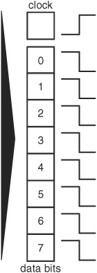
Figure 40-3 In a parallel interface, individual wires are used to carry all the data bits of the communication. A separate clock wire is used to synchronize when the data bits should be read.
One of the most common parallel interfaces you’ll encounter in robotics work is when using the HD7740 controller with a liquid-crystal display (LCD). The HD7740 is the de facto standard controller for all-text LCDs, and it supports a 4-bit-wide port. You communicate with it using four data lines, plus three additional data lines for control. See a working example in Chapter 47, “Interacting with Your Creation.”
SERIAL INTERFACING
The downside to parallel interfaces is that they consume many input and output (I/O) lines on the robot computer or microcontroller. There are only a limited number of I/O lines on the control computer—typically 12 to 16, sometimes fewer. If the robot uses even one 8-bit parallel port, that leaves precious few I/O lines for anything else.
Serial interfaces, on the other hand, conserve I/O lines because they send data on just one or two wires. They do this by separating a byte of information into its constituent 8 bits, then sending each bit down the wire at a time, in single-file fashion (Figure 40-4). Most serial communications schemes use two I/O lines, but there are some that use just one, and others that use three or four (see the next sections). The additional I/O lines are used for such things as timing and coordinating between the data sender and the data recipient.
A number of the sensors you may use with your robot have serial interfaces, and on the surface it may appear they are a tad harder to interface than parallel connections. But, in fact, this is not the case if you use the right combination of hardware and software.
Before you can use the serial data from the sensor, you have to “clock out” all of the bits and assemble them into 8-bit data, which is used to represent some meaningful value—such as distance between the sensor and some object. The task of reconstructing serial data is made easier when you use a microcontroller with built-in serial communications commands. The BASIC Stamp, PICAXE, and Arduino all provide such commands.
Serial communications can be broadly classified into two groups: asynchronous and synchronous.
In asynchronous serial, a single wire is used to convey the bits of data, and to provide necessary timing signals so the listener can follow the conversion. In Figure 40-4, note the idle, start, and stop signals that are part of the 8 bits of data. When idle, the listener knows the talker isn’t sending any data. But the moment a start bit is encountered, the listener knows data is to follow.
In synchronous serial, at least two wires are used: one contains just the data bits, and the other contains a control clock; at each pulse of the clock the listener accepts 1 bit of data. The I2C method, detailed next, is an example of one kind of synchronous serial communication.

Figure 40-4 Asynchronous serial communication uses one wire to carry data bits. Synchronizing the communications—to know when data bits can be sent and received—is handled by so-called start and stop bits embedded in the data.
INTERFACING WITH I2C AND SPI
Because most microcontrollers readily support serial communications via simple-to-use commands, a rising trend in robotics is using serial-based hardware. LCD modules with serial, rather than the typical parallel, interface have long been popular. The same concept is now found on a growing number of other kinds of hardware, such as motor control modules and ultrasonic sensors.
As noted, synchronous serial communication uses two I/O lines: one for data and another for a clock. With each pulse of the clock line, another bit of data is transferred from sender to receiver. One problem with this approach is that you need two I/O lines for every serial link in your system. If you have four serial links, you need eight I/O lines. You need even more I/O lines if you want bidirectional (two-way) communications between the devices.
Several alternative serial protocols are commonly used in microcontrollers that make serial communications more resistant to data errors and reduce the overall pin count when working with multiple serial devices. The two most common are I2C and SPI.
I2C
I2C uses two bidirectional data lines (hence, it’s often referred to as a two-wire interface, shown in Figure 40-5) to connect one or more slave nodes to a single master node. Communication is bidirectional: master and slave can talk to one another.
The two lines of an I2C connection are referred to as SDA and SCL. SDA stands for Serial Data Line, and it contains the data bits themselves; SCL stands for Serial Clock Line, and it contains the clock pulses used to marshal the data.
Technically speaking, I2C is I2C, but the superscript isn’t always shown in discussions or documentation, and is a source of confusion for some. For simplicity, we show it as I2C, and, in fact, many people now refer to it as “eye two see” rather than “eye squared see.” Use whatever form you’re comfortable with.
Common uses of I2C include communicating with sensors and other devices that support it, memory expansion (additional RAM and more EEPROM), and allowing two (or more) microcontrollers to talk to one another. This latter example has numerous applications when using so-called subcontrollers: a main controller that does most of the work, but additional microcontrollers for specific tasks, such as operating motors.
Implementing I2C is fairly simple, when given the right supporting software. For instance, two of the I/O lines on the Arduino microcontroller are designed with I2C in mind. The controller comes with a function library that makes setting up and using I2C relatively painless. In Part 8 there are several examples of using I2C with sensors and the Arduino.
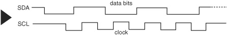
Figure 40-5 Synchronous serial communication uses two (sometimes more) wires; one wire carries the data bits themselves, and the other wire, a clock signal to provide synchronization.

Figure 40-6 Serial peripheral interface (SPI) uses a minimum of four wires for bidirectional communications. But you can set up additional communications links with other devices by adding only one wire for each one.
SPI
SPI, or serial peripheral interface, uses three I/O lines to communicate between master and slave devices, with a fourth I/O line reserved as a kind of “raise your hand” signal to keep everyone from talking at the same time. This fourth I/O is referred to as the Slave Select (SS) line. The functions of all the I/O lines in SPI are aptly named and indicate their roles:
![]() SCLK. Serial Clock (provided by the master).
SCLK. Serial Clock (provided by the master).
![]() MOSI. Master Output, Slave Input.
MOSI. Master Output, Slave Input.
![]() MISO. Master Input, Slave Output.
MISO. Master Input, Slave Output.
To connect two slaves to one master, for example, you need the three main I/O lines wired to each slave. And then you need two additional lines, each one separately wired from the master to the slave. See Figure 40-6 for an example.
Interfacing Outputs
As mentioned previously, most output circuits require more voltage or current than the control electronics (computer, microprocessor, microcontroller) of your robot can provide. You need some way to boost the current needed for proper operation. Techniques include:
Direct connection: Some types of output devices can be driven directly by your robot electronics because their current consumption is low. These typically include LEDs and small piezo buzzers.
Bipolar and MOSFET transistors: Transistors are used to amplify current. With a transistor on the output of a microcontroller it’s the transistor that provides the current to the load, and not the microcontroller.
Motor bridge module: A motor bridge module is a special type of integrated circuit that’s intended to be used to interface to a DC motor. While motor drive is the most common application of these ICs, in fact they can be used to operate just about any high-current application.
Relay: A low-tech but still usable output interface is the mechanical relay. For very small relays you can sometimes connect it directly to your robot’s microcontroller or other electronics, but in most cases you need a resistor and transistor to boost the current.
Interfacing Digital Inputs
The following sections describe common ways to connect digital inputs to the control electronics (microprocessor, computer, or microcontroller) of your robot.
BASIC INTERFACE CONCEPTS
Switches and other strictly digital (on/off) sensors can be readily connected to your robot. The most common methods are:
Direct connection: The most basic interface is simply a wire between devices. This is an acceptable approach when there are no voltage or current issues involved. This is the most common method when connecting switches as inputs to a microcontroller, for use as bump detectors (Figure 40-7), or when connecting a piezo element to produce sound.
Switch debounce: Mechanical switches give dozens to hundreds of false triggers each time they change from opened to closed state. Call these “glitches” or “transients” or bounces, the net effect is the same: your microcontroller may react to each of these false triggers, rerunning the same code multiple times, and causing potential behavioral problems in your robot (if there’s such a thing as attention deficit disorder in a robot, this is it!). A (very) basic switch debounce circuit like that in Figure 40-8 provides a clean transition when the switch changes state. The value of the capacitor can be selected empirically, a fancy word for trial and error—I like to think of it as learning through experimentation! On a switch with lots of glitches you’ll need to select a higher value, but the higher the value, the more sluggish the switch reaction gets. Note the polarity of the capacitor if using a tantalum or aluminum electrolytic components.
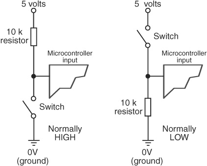
Figure 40-7 Direct connection of an input, in this case a simple switch, to a microcontroller or other circuit.
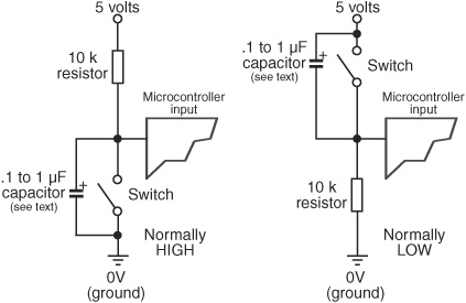
Figure 40-8 Mechanical switches create electrical noise—or “bounces”—when opened or closed. A circuit like this one removes the extra noise, helping the control electronics better determine exactly when the switch is opened or closed.
Limit current: Too much current can kill a microcontroller, and some hardware interfacing may require ways to limit current going into, or out of, the controller. An ordinary resistor (see Figure 40-9) is typically used to limit current. One common use: a resistor between microcontroller and LED. The resistor prevents the LED from drawing too much current, which will definitely destroy the LED and could also damage the microcontroller. Other instances of current limiting include inserting a resistor inline with servo motors and from switches that could carry an electrostatic discharge into the microcontroller. For 5-volt sources, the typical resistor value is between 330 Ω and 680 Ω.
Buffer input: A buffer is any of a number of active electronics between input/output and the controller. There are lots of kinds and uses of buffers; a common form is a transistor between a microcontroller and a relay that operates a motor. The transistor not only helps to isolate the I/O line of the controller, but also boosts current needed to drive the relay. Other forms of buffers include an op-amp and specialty integrated circuits that contain several independent buffered inputs and outputs (Figure 40-10).
USING OPTO-ISOLATORS
Sometimes you might wish to keep the power supplies of the inputs and control electronics totally separate, in order to provide the maximum of protection between input and output. This is most easily done using opto-isolators, which are readily available in IC-like packages. Figure 40-11 shows the basic concept of the opto-isolator: the source controls a light-emitting diode. The input of the control electronics is connected to a photodetector of the opto-isolator.
Note that since each “side” of the opto-isolator is governed by its own power supply, you can also use these devices for simple level shifting, for example, changing a +5 vdc signal to +12 vdc, or vice versa.
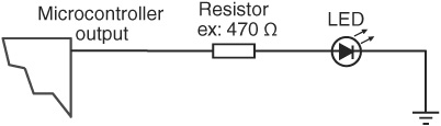
Figure 40-9 Some electronic devices, such as light-emitting diodes, require current limiting, or else damage to the circuit could result. The resistor reduces current to the LED.
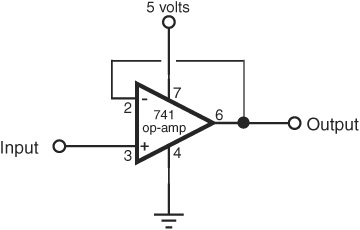
Figure 40-10 A buffer is used to isolate one circuit from another, but it may also be used to provide additional drive current, to invert the digital signal from LOW to HIGH (or vice versa), and for many other applications.
ZENER DIODE INPUT PROTECTION
If a signal source may exceed the operating voltage level of the control electronics, you can use a zener diode to “clamp” the voltage to the input. Zener diodes act like valves that turn on only when a certain voltage level is applied to them. By putting a zener diode across the +V and ground of an input, you can basically divert any excess voltage and prevent it from reaching the control electronics.
Zener diodes are available in different voltages; 4.7- or 5.1-volt zeners are ideal for interfacing to inputs in most robot electronics. You need to use a resistor to limit the current through the zener. Using zeners, and selecting the proper resistor value, requires some simple math, which is detailed in Chapter 19, “Robot Power Systems.”
Interfacing Analog Input
In most cases, the varying nature of analog inputs means they can’t be directly connected to the control circuitry of your robot. If you want to quantify the values from the input, you need to use some form of analog-to-digital conversion, detailed later in this chapter.
Additionally, you may need to condition the analog input so its value can be reliably measured. This may include amplifying, as detailed in this section.

Figure 40-11 An opto-isolator keeps two circuits separate from one another, yet provides a way for one circuit to influence another.
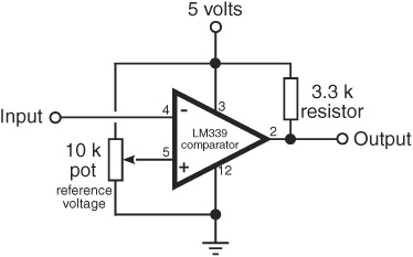
Figure 40-12 In a voltage comparator, an input voltage is compared against a reference voltage. A common scheme is shown here, where the reference voltage is provided by a potentiometer.
VOLTAGE COMPARATOR
The voltage comparator takes an analog voltage and outputs a simple off/on (LOW/HIGH) signal to the control electronics of your robot. The comparator is handy when you’re not interested in knowing the many possible levels of the input, but you want to know when the level goes above or below a certain threshold.
Figure 40-12 shows a common voltage comparator circuit. The potentiometer is used to determine the “trip point,” or threshold, of the comparator. To set the potentiometer, apply the voltage level you want to use as the trip point to the input of the comparator. Adjust the potentiometer so the output of the comparator just changes state.
Note that a pull-up resistor is used on the output of the comparator chip (LM339) used in the circuit. The LM339 uses an open collector output, which means that it can pull the output LOW, but it cannot make it HIGH. The pull-up resistor allows the output of the LM339 to go HIGH when it needs to.
The LM339 integrated circuit actually has four independent voltage comparators in it. This is handy in many robotics experiments, where you want to provide multiple inputs for sensors for the left and right of the robot, or for the front and back.
You might have noticed that the voltage comparator has two inputs, one marked + and the other marked −. These are more commonly referred to as the noninverting and inverting inputs, respectively. You can alter the operation of the comparator by switching the roles of the inputs. That is, instead of having the output of the comparator switch off when the threshold voltage is reached, by flipping the inputs the comparator will turn on.
SIGNAL AMPLIFICATION
Some types of analog sensors don’t provide a signal that is strong enough to be directly used by the rest of your robot’s circuitry. In these instances you must amplify the signal, which can be done by using a transistor or an operational amplifier.
The op-amp method is the easiest in most cases. While the LM741 op-amp is perhaps the most famous, it’s not always the best choice, depending on the application. So I’ve specified an OPA344, which is a low-cost op-amp available from a number of online sources. It provides two benefits over the LM741: its output is rail-to-rail, meaning that assuming a 5-volt supply, the full voltage swing is 0 to 5 volts (or very nearly so). Second, it is made to operate from a single-ended power supply. No need for a split (+ and − power) supply.
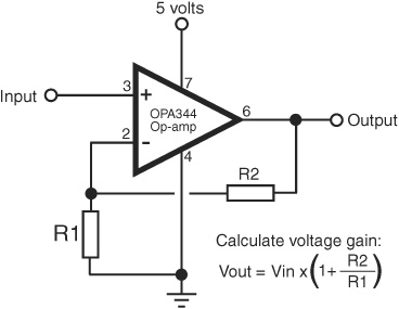
Figure 40-13 The op-amp is a highly versatile circuit, able to amplify and condition signals in hundreds of ways. This is the basic connection scheme for an op-amp designed to amplify a signal.
If you can’t locate an OPA344 chip, you can substitute most any other op-amp that is both rail-to-rail and single-supply.
Figure 40-13 shows the basic op-amp as an amplifier. The resistors marked R1 and R2 set the gain, or amplification, of the circuit. The basic formula to use to calculate approximate voltage gain is provided in the illustration.
OTHER SIGNAL TECHNIQUES FOR OP-AMPS
There are many other ways to use op-amps for input signal conditioning, and they are too numerous to mention here. A good source for simple, understandable circuits is the Forrest Mims Engineer’s Notebook, by Forrest M. Mims III, available at most online bookstores. No robotics lab should be without Forrest’s books.
COMMON ANALOG INPUT INTERFACES
Many types of analog devices can be connected to robot electronics through simple interfaces. Most are engineered to provide a varying voltage, which can then be applied to the analog-to-digital converter of a microcontroller (see later in this chapter), or a voltage comparator, to determine if the voltage exceeds a certain threshold. Among the most common interfaces for robotics:
![]() CdS (cadmium-sulfide) cells are, in essence, variable resistors that are sensitive to light. By putting a CdS cell in series with another resistor between the +V and ground of the circuit (Figure 40-14), a varying voltage is provided that can be read directly into an analog-to-digital converter or voltage comparator. No amplification is typically necessary.
CdS (cadmium-sulfide) cells are, in essence, variable resistors that are sensitive to light. By putting a CdS cell in series with another resistor between the +V and ground of the circuit (Figure 40-14), a varying voltage is provided that can be read directly into an analog-to-digital converter or voltage comparator. No amplification is typically necessary.
![]() A potentiometer forms a voltage divider when connected as shown in Figure 40-15. The voltage varies from 0 volts (ground) to +V. No amplification is necessary.
A potentiometer forms a voltage divider when connected as shown in Figure 40-15. The voltage varies from 0 volts (ground) to +V. No amplification is necessary.
![]() The output of a phototransistor, or light-sensitive transistor, is a varying current that can be converted to a voltage by using a resistor (see Figure 40-16). The higher the resistance, the higher the sensitivity of the device. The output of a phototransistor is typically from 0 volts (ground) to close to +V, and therefore no further amplification is necessary.
The output of a phototransistor, or light-sensitive transistor, is a varying current that can be converted to a voltage by using a resistor (see Figure 40-16). The higher the resistance, the higher the sensitivity of the device. The output of a phototransistor is typically from 0 volts (ground) to close to +V, and therefore no further amplification is necessary.
Figure 40-14 A cadmium-sulfide photo cell is a variable resistor. Its resistance changes depending on the amount of light falling on the sensor. When connected with another resistor, the output of the cell can be read as a varying voltage.
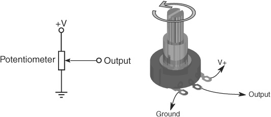
Figure 40-15 A potentiometer provides a convenient way to detect a varying voltage. The shaft of the potentiometer can be connected to a moving part of your robot (like an arm), and the voltage may be used to indicate position.
![]() Like a phototransistor, the output of a photodiode is a varying current. This output can also be converted into a voltage by using a resistor. The output of a photodiode tends to be fairly low. That means amplification is usually required.
Like a phototransistor, the output of a photodiode is a varying current. This output can also be converted into a voltage by using a resistor. The output of a photodiode tends to be fairly low. That means amplification is usually required.
Connecting with USB
USB stands for universal serial bus, and it’s now the most common way for a computer to communicate with devices connected to it. You may frequently use a USB to download programs that you develop on your computer to your microcontroller. In order for your PC and microcontroller to talk via USB, the controller must have a USB connector on it. Microcontrollers that are built on a larger circuit board, such as the Arduino, have integrated USB; when not built-in, USB is available as an option.
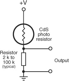
Figure 40-16 A photo transistor is a transistor that is sensitive to light. As light falls on the device, it turns on (conducts current). The more light, the more the transistor turns on. When used with a resistor, the output of the transistor is a variable voltage.
Other methods of communicating between PC and microcontroller include using the older-style serial ports and even the now-almost-forgotten parallel port. Parallel port connections are not as common these days, but many single-chip controllers (PICMicro, AVR, PICAXE) are programmed via the PC serial port. If your computer lacks a serial port, you can use a USB-to-serial converter. These are available from most any local or online store that specializes in personal computers.
Some robo-experimenters prefer to use self-powered USB hubs. Not only do the hubs provide isolation between your project and your PC (protecting your PC in case of a bad short), but because they use their own power supply, they are better able to deliver the requisite current to each port (500 mA for USB 2.0, 900 mA for USB 3.0).
Using Analog-to-Digital Conversion
Computers are binary devices: their digital data is composed of 0s and 1s, strung together to construct meaningful information. But the real world is analog, where data can be most any value, with literally millions of values between “none” and “lots”!
Analog-to-digital conversion is a system that takes analog information and translates it into a digital, or, more precisely, binary, format suitable for your robot. Many of the sensors you will connect to the robot are analog in nature. These include temperature sensors, microphones and other audio transducers, variable output tactile feedback (touch) sensors, position potentiometers (the angle of an elbow joint, for example), light detectors, and more. With analog-to-digital conversion you can connect any of these to your robot.
HOW ANALOG-TO-DIGITAL CONVERSION WORKS
Analog-to-digital conversion (ADC) works by converting analog values into their binary equivalents. Low analog values (like a weak light striking a photodetector) might have a low binary equivalent, such as “1” or “2.” But a high analog value might have a high binary equivalent, such as “255.”
The smaller the change in the analog signal required to produce a different binary number, the higher the “resolution” of the ADC circuit. The resolution of the conversion depends on both the voltage span (0 to 5 volts is most common) and the number of bits used for the binary value to represent the analog voltage.
Suppose the signal spans 10 volts, and 8 bits (or a byte) are used to represent the levels of this voltage. There are 256 possible combinations of 8 bits, which means the span of 10 volts will be represented by 256 different values—from 0 to 255. Figure 40-17 shows a changing analog signal of 1 to 10 volts, with equivalent digital values showing at 0, 5, and 10 volts.
![]() 0 volts is binary 0.
0 volts is binary 0.
![]() 5 volts is binary 127.
5 volts is binary 127.
![]() 10 volts is binary 255.
10 volts is binary 255.
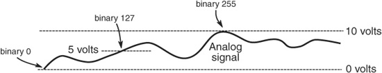
Figure 40-17 How an analog voltage (in this case 0 to 10 volts) is converted to digital values 0 to 255. The full 10 volts is equivalent to binary 255; 0 volts is binary 0. Five volts—halfway between 0 and 10 volts—is binary 127.
Given 10 volts and 8 bits of conversion, the ADC system will have a resolution of 0.039 volts (39 millivolts) per step. Obviously, the resolution of the conversion will be finer the smaller the span or the higher the number of bits. With a 10-bit conversion, for instance, there are 1024 possible combinations of bits, or roughly 0.009 volts (9 millivolts) per step.
ANALOG-TO-DIGITAL CONVERSION ICs
You can construct analog-to-digital converter circuits using discrete logic chips—basically a series of voltage comparators strung together. One much easier approach is a special-purpose ADC integrated circuit. While somewhat “old skool” these days, ADC chips are still widely available, are fairly cheap, and come in a variety of forms. Here are some:
![]() Single or multiplexed input. Single-input ADC chips, such as the ADC0804, can accept only one analog input. Multiplexed-input ADC chips, like the ADC0809 or the ADC0817, can accept more than one analog input (usually 4, 8, or 16). The control circuitry on the ADC chip allows you to select the input you wish to convert.
Single or multiplexed input. Single-input ADC chips, such as the ADC0804, can accept only one analog input. Multiplexed-input ADC chips, like the ADC0809 or the ADC0817, can accept more than one analog input (usually 4, 8, or 16). The control circuitry on the ADC chip allows you to select the input you wish to convert.
![]() Bit resolution. The basic ADC chip has an 8-bit resolution. Finer resolution can be achieved with 10- and 12-bit chips. For example, the LTC1298 is a 12-bit ADC chip that can transform an input voltage (usually 0 to 5 volts) into 4096 steps.
Bit resolution. The basic ADC chip has an 8-bit resolution. Finer resolution can be achieved with 10- and 12-bit chips. For example, the LTC1298 is a 12-bit ADC chip that can transform an input voltage (usually 0 to 5 volts) into 4096 steps.
![]() Parallel or serial output. ADCs with parallel outputs provide separate data lines for each bit. Serial ADCs have a single output, and the data is sent 1 bit at a time. The LTC1298 is an example of an ADC that uses a serial interface.
Parallel or serial output. ADCs with parallel outputs provide separate data lines for each bit. Serial ADCs have a single output, and the data is sent 1 bit at a time. The LTC1298 is an example of an ADC that uses a serial interface.
INTEGRATED MICROCONTROLLER ADCs
Many microcontrollers and single-board computers come equipped with one or more analog-to-digital converters built in. This saves you the time, trouble, and expense of connecting a stand-alone ADC chip to your robot. You just tell the system to fetch an analog input, and it tells you the resulting digital value.
Using Digital-to-Analog Conversion
Digital-to-analog conversion (DAC) is the inverse of analog-to-digital conversion. With a DAC, a digital signal is converted to a varying analog voltage. DACs are common in some types of products, such as audio compact discs.
In the field of robotics, digital-to-analog conversion is typically performed indirectly using an approach referred to as pulse width modulation (PWM). It’s most common in controlling the speed of motors. In operation, a circuit applies a continuous train of pulses to the motor. The longer the pulses are “on,” the faster the motor will go. This works because motors tend to “integrate” the pulses to an average voltage level; no separate digital-to-analog conversion is required. See Chapter 22 for additional information on PWM with DC motors.
When needed, you can accomplish digital-to-analog conversion using integrated circuits specially designed for the task. The DAC08, for example, is a time-honored 8-bit digital-to-analog converter IC. It’s inexpensive (a couple of dollars) and is easy to use.
Expanding Available I/O Lines
A bane of the microcontroller- and computer-controlled robot is the shortage of input and output pins. It always seems that your robot needs one more I/O pin than what’s available. One way to tackle the problem is to drop a feature or two from the robot or even add a second computer or microcontroller. Fortunately, there are other alternatives.
FROM FEW TO MANY
The data demultiplexer, or demux, lets you turn a few I/O lines into many. You’d typically use this in a microcontroller application to expand the number of available outputs—like control eight LEDs with just a few output lines.
Demultiplexers are available in a variety of types; a common component uses three input lines and eight output lines. You can individually activate any one of the eight output lines by applying a binary control signal on the three inputs.
The following table shows the binary control signals using 3 bits to operate eight outputs. The 3 bits are shown in binary format, where 0 means off or LOW, and 1 means on or HIGH. The specific value of the 3 bits corresponds to a selected output. (To operate additional outputs you merely need to set more input control bits. To control 256 outputs, for example, you need 8 bits.)
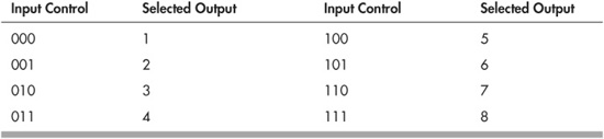
An example of the demultiplexer is the venerable 74138 chip, which is designed to bring the selected output LOW, while all the others stay HIGH. One caveat regarding demultiplexers is that only one output can be active at any one time. As soon as you change the input control, the old selected output is deselected, and the new one is selected in its place.
One way around this is with a serial-to-parallel shift register, such as the 74595 (this is a family of chips; the actual chip you’ll use can be most any member of the family, such as 74HCT595 or 74LS595). The 74595 chip uses three inputs (and optionally a fourth, but for our purposes it can be ignored) and provides eight outputs. Set the outputs you want to activate by sending the 74595 an 8-bit serial word. For example,
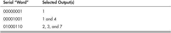
… and so on. Figure 40-18 shows how to set up a 74595 to turn on any of eight LEDs, individually or in groups. In operation, software on your robot’s computer or microcontroller sends eight clock pulses to the Clock line. At each clock pulse, the Data line is sent 1 bit of the serial word you want to use. When all eight pulses have been received, the Latch line is activated. The outputs of the 74595 remain active until you change them (or power to the chip is removed, of course).
If this seems like a lot of effort to expend just to turn three I/O lines into eight, many microcontrollers (and some computers) used for robotics include a “Shiftout” command that does all the hard work for you. A key benefit of the 74595 is that you can “cascade” them to expand the I/O options to more than eight outputs.
FROM MANY TO FEW
So now we want to go the other way: transform many inputs into one. This is the role of the multiplexer (or mux). In the world of microcontrollers, multiplexers are most commonly used to minimize the number of inputs needed to connect to a control circuit. For example, you might use a multiplexer to accept the signals from 12 push-button touch sensors mounted around your robot. All 12 switches are routed through the multiplexer, which in turn connects to just a single input on the microcontroller.
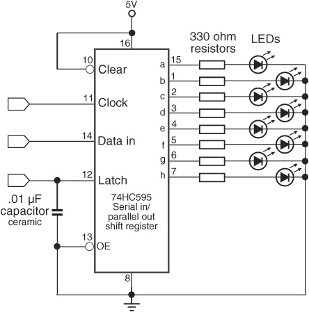
Figure 40-18 How to use a 74595 serial-in, parallel-out (SIPO) IC to exchange serial data to parallel data. The SIPO lets you expand the number of I/O lines from a microcontroller or computer; as shown here, three input lines control eight LEDs.
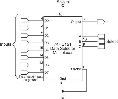
Figure 40-19 Using the 74151 data selector/multiplexer to detect the state of up to 16 inputs. Choose the input to read using the four Select pins; the value of that input appears on the Out pin of the chip.
Multiplexers are the inverse of demultiplexers, and the CD4051 integrated circuit is a good example of how they work. This chip muxes up to eight signals into one, using three Select lines. The bits to specify which input you want are the same as in the preceding table for 8-bit demultiplexing. For instance, to read the value at Input 3, you apply 011 to the three Select lines: the binary value 011 is equal to decimal 3.
ANALOG VERSUS DIGITAL MUX AND DEMUX
Traditional (that is, the most commonly used) multiplexers and demultiplexers are designed for use with digital on/off signals. The SN74151 is a good example; it’s a digital multiplexer—also referred to as a data selector—commonly used to pick from an array of sources and funnel them to a single input. A basic hookup diagram for the SN74151 is in Figure 40-19. Be sure to tie any unused inputs to ground (don’t let them “float”).
The chip accepts up to eight inputs, labeled Inputs in the diagram. The Select pins are then set LOW or HIGH to route the desired input line to the Output. The following table shows which Input pin is active, according to the value of the four Select pins.
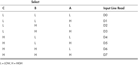
Yet there are analog mux/demux chips available for when working with sensors and other devices that use analog signals. For example, the CD4051 is multipurpose; it functions with digital signals or analog signals. It works the same way as the 75HC151, though its pinouts are different; check the datasheet for the chip for specifics.
![]() Use an analog multiplexer to select from any of a number of analog sources, and route to a single analog input on your microcontroller. Typical use might be reading the value of a series of CdS (a light-dependent resistor) cells. You might arrange a series of 8 or 16 light sensors to form a compound “eye” for your robot, then take individual readings of each one through the multiplexer.
Use an analog multiplexer to select from any of a number of analog sources, and route to a single analog input on your microcontroller. Typical use might be reading the value of a series of CdS (a light-dependent resistor) cells. You might arrange a series of 8 or 16 light sensors to form a compound “eye” for your robot, then take individual readings of each one through the multiplexer.
![]() Use an analog demultiplexer to distribute one input multiple ways. You could use this technique, for instance, to build a series of voltage-controlled oscillators (VCOs) using LM555 timer ICs. By varying the voltages you could create unearthly sound effects and sci-fi-style music.
Use an analog demultiplexer to distribute one input multiple ways. You could use this technique, for instance, to build a series of voltage-controlled oscillators (VCOs) using LM555 timer ICs. By varying the voltages you could create unearthly sound effects and sci-fi-style music.
Chips like the CD4051 can serve as both multiplexers or demultiplexers. Signals can travel through the device in either direction. The eight Inputs become outputs, and the Output becomes an input.
Be on the lookout for ingenious variations on the theme. One is the CD4066 quad bilateral switch IC, a curious critter that contains four single-pole, single-throw (SPST) switches in it. You can wire up the switches with a single common point and use it to combine analog signals—for example, from different sound sources to one amplifier and speaker. Another application is to electronically switch out different components, such as resistors, in a circuit, or to select one of four different voltage levels.
Understanding Port Changing
Port changing is going from serial to parallel, or the reverse. The concept is similar to that of using multiplexers and demultiplexers, but port changing involves more programming when interfacing to a microcontroller, while at the same time offering greater flexibility. Because of the way they work, circuits that change parallel-to-serial and serial-to-parallel are often referred to as shift registers.
PARALLEL GOES IN, SERIAL COMES OUT
Let’s start with changing parallel to serial. This is accomplished using a parallel-in, serial-out, or PISO, chip. An example is the 74165 (and all the various members of the family, such as the 74HCT165); another is the CD4014. The ICs use eight parallel inputs, plus additional pins for loading in the parallel value and providing the serial data output. To use a PISO:
1. Apply the 8 bits to the parallel input pins. For example, this might be the instantaneous condition of eight mechanical bumper switches placed around your robot.
2. Load the parallel data to lock it in. This is done by activating one of the control pins on the chip.
3. Apply clock pulses to the chip, and then read the serial data that comes out. The serial data is a series of LOW and HIGH signals, timed with the clock you provide. So a sequence of:
0 1 0 0 1 1 0 1
means the parallel input pins in these positions are LOW for a 0 and HIGH for a 1.
FROM SERIAL TO PARALLEL, WITH LOVE
Okay, I thought of that dumb joke because I’m listening to a James Bond soundtrack CD. Anyway, going from serial to parallel is the inverse of the above, with obvious consequence. These types of circuits are known as serial-in, parallel-out, or SIPO, which you were introduced to previously in the section “Expanding Available I/O Lines.” Besides the 74595, a popular IC that handles this task is the 74164 (this is a family of ICs that include the 75HC164, 74LS164, and others; you can use most any of them). A basic connection diagram is shown in Figure 40-20.
As with demultiplexers (see the preceding sections), SIPO circuits are handy for just about any situation where you want to expand just a few I/O ports to many. In robotics a common use of the SIPO is to illuminate multiple light-emitting diodes, without requiring one pin for each LED. One SIPO chip, using two pins of a microcontroller, can operate eight LEDs. To get any combination of LEDs to light, you merely apply 8 bits of serial data, clocking in each, and toggling the Clock pin of the chip.
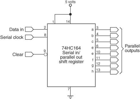
Figure 40-20 Using the 74164 shift register to convert simple serial data to 8 bits of parallel data.
The 74164 is an example of a nonlatching SIPO, meaning that as you enter data, the chip starts changing its parallel outputs immediately. This is usually of no concern for tasks like LED displays and when you clock in the data very quickly. The CD4094 IC is an example of a SIPO with latching outputs, meaning that the outputs won’t change until (and unless) you change the latch pin.
CASCADING SHIFT REGISTERS
Many (but not all) shift register ICs let you cascade or daisy-chain them one after the other, so you can work with more bits. Cascading makes the most sense—at least for robotics—when using a SIPO. A single serial data train can control 8, 16, 24 … up to 256 parallel outputs.
SPECIALTY I/O EXPANDER CHIPS
For microcontrollers that are short on available input/output pins there are also specialty I/O expander integrated circuits. Many use the I2C serial interface standard to communicate with a host processor and offer 8, 16, and even more input and outline lines.
Examples of I/O expander chips include the PCF8575 from Texas Instruments and NXP, Microchip MCP23016, NXP PCA9555N, and the Maxim MAX7314. Most expander ICs are in the range of $3 to $5, and are available through the larger online electronics distributors, such as Digikey and Mouser. If there’s a downside to expander chips it’s this: most come only in surface-mount packages. The MCP23016 is one of a few exceptions, and it is available in a DIP-style package. For the others you’ll need a generic surface-mount carrier or a custom “breakout board” that allows you to use the chip with standard breadboards.
![]()
Check the RBB Online Support site for circuits and programming examples using several popular I/O expander chips. See Appendix A for more details on the support site.
On the Web: Understanding Bitwise Port Programming
Each of the pins on a microcontroller can be controlled independently. Many controllers also let you work with multiple pins at a time. When pins are combined, they form a port. I/O pins are most often grouped in sets of eight, to create 8-bit ports.
With bitwise port programming, you can manage all the bits of the port as a whole. This makes the programming code easier for certain tasks, like operating a string of LEDs or a bunch of motors. Check out the RBB Online Support site (see Appendix A) for a detailed look at bitwise port programming.