
Chapter 44
Robotic Eyes
For a robot to be truly useful it needs senses; the more senses, the better. It’s easy to endow even the most basic robot with a sense of touch—all it takes is a couple of small switches, or maybe an infrared or ultrasonic detector here and there.
But things get a little tougher when it comes to the sense of sight. Producing images for a robot to see is no problem; you need nothing more than an inexpensive video camera. The trouble comes when trying to make sense of those images … is that the family cat pretending to be asleep in the middle of the living room, or is it a pair of old, discarded socks?
Despite the challenges in endowing a robot with eyes, there are a number of affordable and relatively easy methods of creating robotic vision, including rudimentary “Cyclops” vision systems that are used to detect the presence or absence of light, as well as more elaborate arrays of sensors to decode relative intensities of light. Let’s get started.
![]()
Source code for all software examples may be found at the RBB Online Support site. See Appendix A, “RBB Online Support,” for more details. To save page space, the lengthier programs are not printed here. The support site also offers source code with added comments, parts lists (with sources) for projects, updates, extended construction plans, and more examples you can try!
Simple Sensors for Robotic Eyes
Throughout this chapter I’m going to limit the discussion to the low end of the spectrum: with $10,000 you can purchase a robust machine vision system and do most anything with it. Alas, this is a tad bit higher than most of us have to spend! Everything here can be done for $0 to $100, much of it at the low end of this scale.
So to start, most people think about “robot vision” as some full video-like snapshot, complete with auxiliary text explaining what’s going on, a la Terminator. It’s not always like that. A number of very simple electronic devices can be used as very effective eyes for your robot. These include:
![]() Photoresistors, which are also known as light-dependent resistors and photocells
Photoresistors, which are also known as light-dependent resistors and photocells
![]() Phototransistors, which are like regular transistors, except they are activated when light strikes them
Phototransistors, which are like regular transistors, except they are activated when light strikes them
![]() Photodiodes, which are photo-sensitive diodes that begin to conduct current when exposed to light
Photodiodes, which are photo-sensitive diodes that begin to conduct current when exposed to light
Photoresistors, photodiodes, and phototransistors are connected to other electronics in the same general way: you place a resistor between the device and either +V or ground. This forms a voltage divider. The point between the device and the resistor is the output, as shown in Figure 44-1. With this arrangement, the device outputs a varying voltage.
PHOTORESISTORS
Photoresistors are typically made with cadmium sulfide, so they are often referred to as CdS cells or photocells. A photoresistor functions as a light-dependent resistor (also known as an LDR): the resistance of the cell varies depending on the intensity of the light striking it.

When no light strikes the cell, the device exhibits very high resistance, typically in the high 100 kilohms, or even megohms. Light reduces the resistance, usually significantly—a few hundreds or thousands of ohms.
Photoresistors are easy to interface to other electronics. Figure 44-2 shows two ways to connect photoresistors to a circuit. The resistor is selected to match the light and dark resistance of the particular photocell you’re using. You’ll need to experiment a bit here to find the ideal resistor value. Start with 100 kΩ and work your way down. A 100 kΩ potentiometer works well for testing. If you use a pot, add 1 kΩ to a 5 kΩ resistor in series with it to prevent a near short circuit when the photocell is exposed to bright light.

Figure 44-1 The output of photoresistors, phototransistors, and photodiodes can be converted to a varying voltage by using a divider resistor. You may measure the voltage with a multimeter.
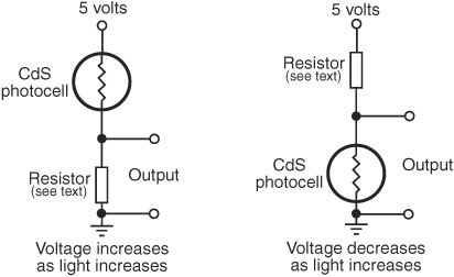
Figure 44-2 A CdS photocell, the most common type of photoresistor, may be connected so that the output voltage increases or decreases with more light. Experiment with the value of the fixed resistor for best sensitivity.
Note that photocells are fairly slow reacting, and are unable to discern when light flashes more than 20 or 30 times per second. This trait actually comes in handy because it means photoresistor cells basically ignore the on/off flashes of AC-operated lamps. The cell still sees the light, but isn’t fast enough to track it.
PHOTOTRANSISTORS
All semiconductors are sensitive to light. If you were to take the top off of a regular transistor, it would act as a phototransistor. Only in a real phototransistor, the light sensitivity of the device is much enhanced. A glass or plastic cover protects the delicate semiconductor material inside. Many phototransistors come in a package that looks a lot like an LED. And like an LED, one side of the plastic case is flattened. Unless otherwise indicated in the datasheet for the phototransistor, the flat end denotes the collector (C) lead. The other lead is the emitter (E).

Unlike photoresistors, phototransistors are very quick acting and able to sense tens of thousands of flashes of light per second. Because of this, they can be used for optical data communications. It also means that when used under AC-operated or fluorescent lamps, the output of the sensor can rapidly vary as it registers the fluctuation in light intensity.
The output of a phototransistor is not “linear”; that is, there is a disproportionate change in the output of a phototransistor as more and more light strikes it. A phototransistor can become easily “swamped” with too much light. Even as more light shines on the device, the phototransistor is not able to detect any more change.
See Figure 44-3 for ways to connect a phototransistor to the rest of a control circuit. Like the photoresistor, experiment with the value of the fixed resistor to determine the optimum light sensitivity. Values of 4.7 kΩ to 250 kΩ are typical, but it depends on the phototransistor and the amount of light that you want to cause a trigger. Start with a lower-value resistor and work your way up. Higher resistances make the circuit more sensitive.

You may instead wish to add a small, 250 kohm potentiometer in series with a 1 kΩ to 5 kΩ fixed resistor. Dial the potentiometer for the sensitivity you want. Connect your multimeter as shown in Figure 44-5 to test the voltage swing you get under light and no-light situations. I like to select a resistor so that the sensor outputs about half of the supply voltage (that is, 2.5 volts) under ambient, or normal, light levels.
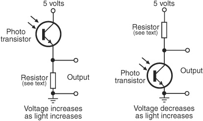
Figure 44-3 Variations in connecting a phototransistor to the rest of the circuit. The output is a varying voltage. Experiment with the value of the fixed resistor for best sensitivity.
PHOTODIODES
These work much like phototransistors but are simpler devices. Like phototransistors, they are made with glass or plastic to cover the semiconductor material inside. And like phototransistors, photodiodes are very fast acting. They can also become “swamped” when exposed to extrabright light—after a certain point, the device passes all the current it’s going to, even as the light intensity increases.
Photodiodes are essentially LEDs in reverse; in fact, you can even use some LEDs as photodiodes, though as sensors they aren’t very sensitive.
If you’d like to experiment with the LED-as-photodiode trick, try to find one that’s in a “water-clear” casing. The light should enter straight into the top of the LED; off to the sides doesn’t work. You might need a simple focusing lens to improve the light-gathering capability. The LED is most sensitive to light at the same wavelength as the color it produces. To register green light, use a green LED, for example.
One common characteristic of most photodiodes is that their output is rather low, even when fully exposed to bright light. This means that, to be effective, the output of the photodiode must usually be connected to a small operational amplifier or transistor amplifier.
SPECTRAL RESPONSE OF SIMPLE SENSORS
Light-sensitive devices differ in their spectral response, which is the span of the visible and near-infrared light region of the electromagnetic spectrum that they are most sensitive to. As depicted in Figure 44-4, CdS photoresistors exhibit a spectral response close to that of the human eye, with the greatest degree of sensitivity in the green or yellow-green region.
Both phototransistors and photodiodes have peak spectral responses in the infrared and near-infrared regions. In addition, some phototransistors and photodiodes incorporate optical filtration to decrease their sensitivity to a particular part of the light spectrum. In most cases, the filtration intentionally makes the sensors more sensitive to infrared and near-infrared light, and less to visible light.
A few special-purpose photodiodes are engineered with enhanced sensitivity to shorter-wavelength light. This allows them to be used with ultraviolet emitters that cause paint and ink pigments to fluoresce in the visible light spectrum. These are used, for example, in currency verification systems. For robotics you might use such a sensor to follow a line on the ground painted with a fluorescent dye.

Figure 44-4 Comparison of the light spectrum sensitivity of the human eye, the CdS photoresistor, and the most common form of phototransistor. Visible light is between about 400 nanometers (nm) and 750 nm.
Building a One-Cell Cyclops Eye
A single light-sensitive photoresistor is all your robot needs to sense the presence of light. As noted, the photoresistor is a variable resistor that works much like a potentiometer but has no control shaft. You vary its resistance by increasing or decreasing the light shining on it.
Connect the photocell as shown in the “voltage increases as light increases” version of Figure 44-2. As explained in the previous section, a resistor is placed in series with the photocell and the “output tap” is between the cell and resistor. This converts the output of the photocell from resistance to voltage. Voltages are a lot easier to measure in a practical circuit.
Typical resistor values are 1 to 10 kΩ, but this is open to experimentation. You can vary the sensitivity of the cell by substituting a higher or lower value. Test the cell output by connecting a multimeter to the ground and output terminals, as shown in Figure 44-5. For experimenting, you can connect a 2 kΩ resistor in series with a 50 kΩ potentiometer—these replace the single resistor that’s shown. Try testing the cell at various settings of the pot.
So far, you have a nice light-to-voltage sensor, and when you think about it, there are numerous ways to interface this ultrasimple circuit to a robot. One way is to connect the output of the sensor to the input of a comparator. The LM339 quad comparator IC is a good choice. The output of the comparator changes state when the voltage at its input goes beyond or below a reference voltage or “trip point.”
In the circuit shown in Figure 44-6, the comparator is hooked up so the noninverting input (marked +) serves as a voltage reference. Adjust the potentiometer to set the trip point higher or lower than what you want to trigger at. To begin, set it midway, then adjust the trip point higher or lower as you experiment with different light levels. The output of the photoresistor circuit is connected to the inverting input (marked −) of the comparator. When the voltage at this pin goes above or below the point with the potentiometer, the output of the comparator changes state.

Figure 44-5 How to test a CdS photoresistor using a multimeter. Dial the meter to read DC voltage, then take the measurement as shown.
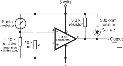
Figure 44-6 Using an LM339 voltage comparator to provide a basic on/off output from a photoresistor (this also works with a phototransistor). Adjust the 10 kΩ potentiometer so that the comparator triggers at just the desired amount of light.
With the wiring shown, the output goes from HIGH to LOW as the light increases. One application is to adjust the potentiometer so that under normal room light the output of the ’339 just goes HIGH. Shine a light directly into the sensor, and the output switches LOW.
If you want the opposite effect—the output goes from LOW to HIGH under increasing light—simply switch the connections to pins 4 and 5 of the comparator. This makes the logic go in reverse.
The circuit also shows an optional LED and resistor, useful as a visual indicator, for testing purposes only. The LED will wink on when the output of the comparator goes HIGH and wink off when it goes LOW. Remove the LED and resistor if you connect the comparator to another digital circuit, such as a microcontroller.
CREATING A LIGHT-RECEPTIVE ROBOT
One practical application of this circuit is to detect light levels that are higher than the ambient light in the room. Doing so enables your robot to ignore the background light level and respond only to the higher-intensity light, like a flashlight. You don’t even need a microcontroller or other brain for your robot. It can be done using only simple components and a relay. Figure 44-7 shows one example of an old-skool bot that reacts to light falling on a phototransistor.
To begin, set the 10 kΩ potentiometer so that in a darkened room the circuit just switches HIGH (this deenergizes the relay). Use a flashlight with fresh batteries to focus a beam directly onto the phototransistor. Watch the output of the comparator change state from HIGH to LOW. When LOW, the relay is energized through the 2N3906 PNP transistor.
You can use this so-simple-it’s-dumb circuit to activate your robot so it will move toward you when you turn the flashlight on it. Or the inverse: It runs away from you. Just reverse the connections to the motor.
You can also use photoresistors instead of phototransistors. Experiment with the value of the series resistor. You’ll need to pick a value that best matches the actual photocells you are using.
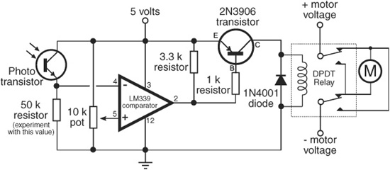
Figure 44-7 All-in-one control circuit for operating a motor based on the amount of light falling on a phototransistor. When the relay triggers, the motor reverses. Adjust the light sensitivity of the circuit by changing the value of the fixed resistor below the phototransistor.
When your robot advances toward the light, it’s said to be photophilic—it “likes” light. When your robot shies away from the light, it’s said to be photophobic—it “hates” light. When combined with other actions, these behaviors allow your robot to exhibit what appears to be artificial intelligence.
![]()
Look for more light-dependent robot examples on the RBB Online Support site (see Appendix A), including microcontroller code for a completely programmed light-follower/light-avoider bot.
Building a Multiple-Cell Robotic Eye
The human eye has millions of tiny light receptacles. Combined, these receptacles allow us to discern shapes, to actually “see” rather than just detect light levels. A surprisingly useful implementation of human sight is given in Figure 44-8. In this design by robotics guru Russell Cameron, eight phototransistors are connected in four sets of two; the four sets are then routed to four separate inputs of a microcontroller. A benefit of this design is that it’s also available as a low-cost commercial product from DAGU Electronics, provided by several online specialty robotics stores, including RobotShop.
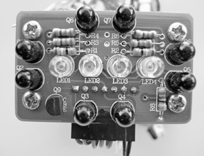
Figure 44-8 “Compound eye” created with four infrared LEDs and eight phototransistors. The phototransistors are in four groups of two, placed on the top, bottom, left, and right, allowing the sensor to detect basic orientation of obstacles in front of it.
Under program control, the Arduino selects one of the four inputs while illuminating the scene immediately ahead of the phototransistors by turning on a set of infrared LEDs. Each of the four sets of phototransistors is read in turn. The sensor can detect objects 6″ to 8″ away, and in the case of a hand, ankle, ball, or kitten, can determine whether the offending object is directly in front of it or to the sides.
This project shows a compound robotic eye with eight individual light sensors, but you can build it using more or fewer sensors if you wish. While you could conceivably build a vision component with greater than 32 phototransistors, it would end up being a pretty big and ungainly eye.
PHYSICAL CONSTRUCTION OF THE COMPOUND EYE
Figure 44-9 shows the layout of the eye, and Figure 44-10 shows the wiring diagram. The infrared LEDs are located in the center of the eye sensor board, the four pairs of phototransistors on each of the four sides.
All the LEDs and all the phototransistors should be identical, and, for the best results, they should be brand-new prime components. Surplus and odds-and-ends components may vary too much in their output to be useful. If you can, select 4.7 kΩ resistors with a 1 percent or 2 percent tolerance. For best results, select phototransistors with a built-in infrared filter. These will look dark red, dark blue, or brown. The filtration will help block unwanted room light. Operate the eye indoors, under modest light. Bright lights or sunlight will reduce its effectiveness.
TESTING PROGRAM
Program flyeye.pde contains the Arduino code for testing the compound eye. Use the circuit in Figure 44-11 to visually see the sensors in action. Slowly wave your hand side to side and up and down. The four indicator LEDs should light in response to your movements. The program assumes the eyes are connected top, bottom, left, and right, as shown in Figure 44-9. If the eyes are switched around on your prototype, then simply alter the wiring to the A0 to A3 analog inputs of the Arduino.
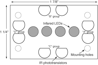
Figure 44-9 LED and phototransistor layout of the compound eye.
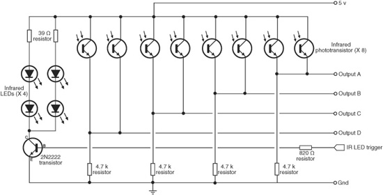
Figure 44-10 Hookup diagram for the compound eye. The LEDs may be turned on and off (when not needed), or pulsed to provide basic modulation. (Circuit courtesy Russell Cameron.)
Note the thresh variable; it sets the threshold, or sensitivity, of the eyes. Decrease the value of thresh to increase the sensitivity. The practical minimum value depends on many factors. In my tests the minimum threshold for all eyes was about 200, but that caused false reads now and then. I set it to 250 for an extra margin of safety. (The thresh value was set with the four IR LEDs activated; the number is a lot lower when the LEDs are off and the eyes are responding only to the natural light of the room.)
You can test the numeric values from each pair of the eyes with this code:
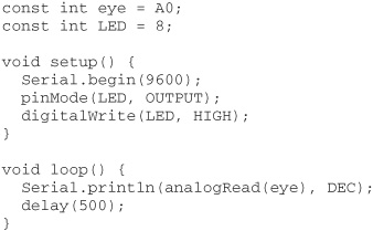
Open the Serial Monitor window and look at the number returned from the eye connected to analog line A0. Change the first line to A1, A2, or A3 to read the other pairs of eyes.
You may find that under the exact same lighting conditions some of the eyes return higher or lower values. This is due to differences in the phototransistors, their mounting, and the tolerance of the 4.7 kΩ resistors you use. As needed, you can set a different threshold for each eye in order to “balance them out,” but you’ll probably find that isn’t necessary as long as the eyes are within about 100 points of one another.
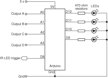
Figure 44-11 Hookup scheme for the compound eye and the Arduino microcontroller. The four outputs of the eye connect to four of the Arduino’s ADC inputs. A set of LEDs visually indicate when a set of eyes has detected an object.
flyeye.pde

To save space, the program code for this project is found on the RBB Online Support site. See Appendix A, “RBB Online Support,” for more details. Additional examples are provided that demonstrate using the compound eye to directly control a two-wheeled robot.
DEALING WITH LIGHT SPOILAGE
The bane of any light-sensitive detector is spoilage from stray light sources. Examples include:
![]() Infrared light coming from outdoors, a desk lamp, or other source, and not from the infrared LEDs you have so carefully placed on your robot. You can help mitigate this by using tubes and baffles to block unwanted light. A simple light tube can be constructed using a small piece of black heat shrink tubing (not shrunk) cut to length and placed around the sensor.
Infrared light coming from outdoors, a desk lamp, or other source, and not from the infrared LEDs you have so carefully placed on your robot. You can help mitigate this by using tubes and baffles to block unwanted light. A simple light tube can be constructed using a small piece of black heat shrink tubing (not shrunk) cut to length and placed around the sensor.
![]() Ambient (natural room) light striking the sensor from the sides, or even from behind, rather than straight down its gullet. CdS photocells are sensitive to light coming from behind them (through their backing). To avoid this spoilage, always place your photoresistors against a black or opaque backstop that will block light.
Ambient (natural room) light striking the sensor from the sides, or even from behind, rather than straight down its gullet. CdS photocells are sensitive to light coming from behind them (through their backing). To avoid this spoilage, always place your photoresistors against a black or opaque backstop that will block light.
![]() Light spilling from the side of the LED and directly into the sensor. Use the heat shrink tubing trick, or add a heavy felt baffle between the two. It also helps to position the LED slightly forward of the sensor.
Light spilling from the side of the LED and directly into the sensor. Use the heat shrink tubing trick, or add a heavy felt baffle between the two. It also helps to position the LED slightly forward of the sensor.
![]() Visible-light LEDs and LCD display panels that are located too close to the sensor. Their light can accidentally influence the sensor. Be sure to always locate your light sensors away from any potential light sources.
Visible-light LEDs and LCD display panels that are located too close to the sensor. Their light can accidentally influence the sensor. Be sure to always locate your light sensors away from any potential light sources.
Using Lenses and Filters with
Light-Sensitive Sensors
Simple lenses and filters can be used to greatly enhance the sensitivity, directionality, and effectiveness of both single- and multicell vision systems. By placing a lens over a small cluster of light cells, you can concentrate room light to make the cells more sensitive to the movement of humans and other animate objects. And you can also use optical filters to enhance the operation of light cells.
See The RBB Online Support site (refer to Appendix A) for an extended discussion of selecting and using lenses and filters with robotic optical systems.
Video Vision Systems: An Introduction
The one sense that offers the most potential to the science of robotics is also the most elusive: vision. Robotic sight is something of a paradox. The sensor for providing a video image is actually quite mundane, you can now purchase black-and-white video cameras for under $20, complete with lens.
But there’s a second part to the vision equation: what to do with the image data once it’s been acquired. There is a burgeoning science of machine vision that seeks to provide answers.
The single- and multicell vision systems described previously are useful for detecting the absence or presence of light, but they cannot make out anything except very crude shapes. This greatly limits the environment into which such a robot can be placed. By detecting the shape of an object, a robot might be able to make intelligent assumptions about its surroundings and perhaps navigate those surroundings, recognize its “master,” and more.
FYI
The machine vision described here is different from video beamed from a robot back to its human operator. The latter technique is used in teleoperated robots, where you get to see what the robot sees. Video for teleoperation is covered in Chapter 41, “Remote Control Systems.”
CAMERAS AND EQUIPMENT
A video system for robot vision need not be overly sophisticated. The resolution of the image can be as low as about 300 by 200 pixels. A color camera is not mandatory, though in some kinds of vision analysis techniques, the use of color is how the system tracks objects and movement.
Video systems that provide a digital output are generally easier to work with than those that provide only an analog video output. You can connect digital video systems directly to a PC, such as through a serial, parallel, or USB port. Analog video systems require the PC to have a video capture card, fast analog-to-digital converter, or similar device attached to it.
PC-BASED VISION
If your robot is based on a laptop or desktop personal computer, you’re in luck! There’s an almost unlimited array of inexpensive digital video cameras that you can attach to a PC. The proliferation of Webcams for use with personal computers has brought down the cost of these devices to under $50, and often less for bare-bones models. You can use a variety of operating systems—Windows, Linux, or Macintosh—though be forewarned that not every Webcam has software drivers for every operating system. Be sure to check before buying.

Figure 44-12 A screenshot of a color threshold window in the RoboRealm computer vision software. (Courtesy RoboRealm.)
Connecting the camera to the PC is the easy part; using its output is far more difficult. You need software to interpret the video scene that the camera is capturing. An example is RoboRealm, at www.roborealm.com. RoboRealm (see a screenshot in Figure 44-12) is a set of low-cost vision analysis tools that allows your tobor to recognize shapes and objects, and even track them in real time.
You’ll also want to track down past issues of Nuts and Volts and SERVO magazines, both of which have published excellent articles on machine vision. If you don’t have them already, back issues are available on CD-ROM. Look for the series written by robot vision expert Robin Hewitt.
If you’re a user of the .NET programming platform under Windows and are fairly familiar with C# or VB programming, be sure to investigate the DirectShow.Net Sourceforge open-source project at directshownet.sourceforge.net. DirectShow.Net is a managed .NET wrapper that allows you to tap into the incredibly powerful DirectShow architecture of Windows, without the need to use C++.
The project authors provide samples of capturing video, and several samples demonstrate how to retrieve the bitmap of each video frame as it goes through the system. With this bitmap you can write your own image analysis routines, such as looking for pixels of a specific color. Or you can use fairly simple scene-averaging techniques to determine if there’s movement in the frame.
OTHER EXAMPLES OF MICROCONTROLLER-BASED VISION
A PC makes it easy to integrate a Webcam, but it’s not the only way to provide vision to your robot. Several microcontroller-based vision systems are available that work with most any robot brain, including inexpensive MCUs like the Arduino or BASIC Stamp.

Figure 44-13 Composite video is composed of many separate lines that together make a whole picture. This graph shows just one line of video, starting with a sync signal.
A popular microcontroller-based vision solution is the CMUcam, available commercially from a number of specialty robotics stores; see Appendix B, “Internet Parts Source” for a list of some of these. This device incorporates a color imager, lens, and image analysis circuitry. The CMUcam tracks objects by color and motion. It can connect to a computer or microcontroller via a serial data link.
USING COMPOSITE VIDEO FOR VISION
In the modern digital world, it’s sometimes easy to forget that analog isn’t dead—not by a long shot. Most low-cost black-and-white and color security cameras provide an analog composite video signal, for direct connection to a time-lapse VCR or television monitor.
There are several standards used for video signals—NTSC and PAL being the two most common around the world. Select a camera that supports the standard used in your location. NTSC is used in North America, Japan, and Canada, and PAL is used in most of Europe, Australia, and China. (A third system, called SECAM, is used in Russia and France, among others.)
Technically speaking, NTSC defines a standard for providing color. The RS-170 video standard defines the basic video signal format used with NTSC. Even for a black-and-white camera, manufacturers will still often state that their product is “NTSC compatible.”
In order to process video from a composite video camera, you need a means to separate out the different parts of the signal. Monochrome video is composed of two major components: sync and video (see Figure 44-13). Low-cost integrated circuits like the LM1881, ($3 from Digikey, Newark, and other chip distributors; use www.findchips.com to locate a source) allow you to apply a composite video signal and get back separate outputs for vertical and composite sync.
With a microcontroller, you can use these signals as a means to synchronize with the video information that is also being provided by the camera. You can capture a full frame of video or analyze one line of video at a time.
In order to effectively use a sync separator IC like the LM1881, you should have a fairly good understanding of how analog video works. As this is an old technology, you can check the local library for books on the subject. Even one a few decades old will give you the framework for developing custom vision projects using analog video. Refer to Appendix A, “RBB Online Support,” for links to learn more about processing analog video using the LM1881 and other techniques.