
Chapter 21
Choosing the Right Motor
Motors are the muscles of robots. Attach a motor to a set of wheels, and your robot can scoot around the floor. Attach a motor to a lever, and the shoulder joint for your robot can move up and down. Attach a motor to a roller, and the head of your robot can turn back and forth, scanning its environment. There are many kinds of motors; however, only a select few are truly suitable for homebrew robotics. In this chapter, we’ll examine the various types of motors and how they are used.
AC or DC Motor?
Direct current—DC—dominates robotics; it’s used as the main power source for operating the onboard electronics, for opening and closing relays, and, yes, for running motors that propel a robot across the floor. Figure 21-1 shows a gallery of over a half dozen small DC motors suitable for building small robots. They’re inexpensive, and they adapt easily to most any robot design. You’ll learn how in this chapter and the ones that follow.
The alternative motor type, alternating current (AC), is seldom used in robotics. AC motors are best suited for things like household fans and other applications where power comes from a wall socket.
FYI
Not sure what AC and DC mean? Refer to the lessons in My First Robot, found on the RBB Online Support site (see Appendix A). There you’ll find a crash course in various electronics subjects.
When looking for DC-suitable motors, be sure the ones you buy are reversible. Few robotic applications call for motors that run in one direction only. DC motors are inherently bidirectional, but some design limitations may prevent reversibility, so this is something you have to be on the lookout for.

Figure 21-1 A menagerie of DC motors, with and without gear reduction boxes. These motors operate at low voltages, all of them under 12 volts and most under 6 volts—ideal for the typical battery-run robot.
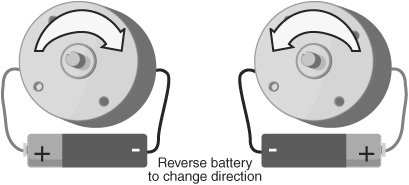
Figure 21-2 The direction of rotation of most DC motors may be altered simply by reversing the polarity of its power connections. With a battery or other DC power source connected one way, the motor spins clockwise. Reverse the polarity, and the motor spins counterclockwise.
The best and easiest test for reversibility is to try the motor with a suitable battery, as shown in Figure 21-2. Apply the power leads from the motor to the terminals of the battery or supply. Note the direction of rotation of the motor shaft. Now reverse the power leads from the motor. The motor shaft should rotate in reverse.
Continuous or Stepping Motor?
DC motors can be either continuous or stepping. Here is the difference: with a continuous motor, the application of power causes the shaft to rotate continuously (hence the name). The shaft stops only when the power is removed or if the motor is stalled because it can no longer drive the load attached to it.
With stepping motors, the application of power causes the shaft to rotate a few degrees, then stop. To keep rotating the shaft, power must be pulsed to the motor. Stepping motors are used when you want to control how far a motor turns, in either direction. They don’t have the mechanical torque that a continuous DC motor has, but they’re useful for certain tasks that don’t need brute force. For example, one application is to spin a turret on top of a robot; on the turret might be a sensor of some kind or maybe a gun that shoots foam bullets. Chapter 22, “Using DC Motors,” focuses entirely on continuous motors.
![]()
Stepping motors were covered in previous editions of Robot Builder’s Bonanza. Because stepping motors are not as heavily used in robots as they used to be, the material has been removed from the printed book and is available on the RBB Online Support site (see Appendix A) as a free download.
Servo Motors
A special subset of continuous motors is the servo motor, which in typical cases combines a continuous DC motor with electronic feedback to ensure the accurate positioning of the motor. A common form of servo motor is the kind used in model and hobby radio control (R/C) cars and planes. We use these a lot in robotics, so this is a vital motor to get to know.

Figure 21-3 Servo motors for radio control (R/C) model airplanes and cars are DC motors, but with added control electronics and built-in gear reduction.
Compare the R/C servo motor in Figure 21-3 with the DC motors in Figure 21-1. The first thing you’ll notice is that R/C servo motors come in a neat little rectangular box. This is one of their most alluring traits. Sizes of R/C servos are standardized (more or less), and they even have standardized mounting flanges, allowing you to easily add them to your robot creations.
R/C servos can be—and often are—used for the same jobs as stepper motors. Because they’re cheaper, easier to find, and simpler to use than steppers, R/C motors have almost completely replaced the stepper motor in amateur robot designs.
For this reason, we devote a separate chapter just to them. See Chapter 23, “Using Servo Motors,” for more information on using R/C servo motors—not only to drive your robot creations across the floor but to operate robot legs, arms, hands, heads, and just about any other appendage.
Motor Specs
Motors come with extensive specifications. The meaning and purpose of some of the specifications are obvious, but for others, they aren’t. Of all the specifications for motors, only a small handful are truly meaningful to the amateur robot builder, so I’ll just concentrate on those. These specs are operating voltage, current draw, speed, and torque.
OPERATING VOLTAGE
All motors are rated by their operating voltage. With some small DC “hobby” motors, the rating is typically a range, something like 4.5 to 6 volts. For others, an exact voltage is specified. Either way, most DC motors will run at voltages higher or lower than those specified for it. A 6-volt motor is likely to run at 3 volts, but it won’t be as powerful. It will also run slow.
Many motors will refuse to run, or will not run well, at voltages under about 40 or 50 percent of the specified rating. Similarly, a 6-volt motor is likely to run at 12 volts. As you may expect, as the speed of the motor increases, the motor will exhibit greater power.
![]()
I don’t recommend that you run a motor continuously at more than 50 to 80 percent its rated voltage, at least not for long. The electrical windings inside the motor may overheat, which can cause permanent damage to the motor. Motors not designed for high-speed operation may turn faster than their construction allows, which literally could cause them to burn up.
If you don’t know the voltage rating of a motor, you can take a wild guess at it by trying various voltages and seeing which one provides the greatest power with the least amount of heat and mechanical noise. Let the motor run for several minutes, then feel the heat on the outside of the motor case. Listen to the motor; it should not seem as if it is straining under the stress of high speeds.
CURRENT DRAW
Current draw is the amount of current, in milliamps or amps, that the motor requires from the power supply. Current draw is more important when the specification describes motor loading, that is, when the motor is turning something or doing work. The current draw of a free-running (no-load) motor can be quite low. But have that same motor spin a wheel propelling a robot across the floor, and the current draw might increase several hundred percent.
Most DC motors use a permanent magnet inside. In these motors, which are the most common, current draw increases with load. You can see this visually in Figure 21-4. The more the motor has to work to turn the shaft, the more current is required. The load used by the manufacturer when testing the motor doesn’t follow any kind of standard, so in your application the current draw may be more or less than that specified.
A point is reached when the motor does all the work it can do and no more current will flow through it. The shaft stops rotating; the motor has stalled. This is considered the worst-case condition. The motor will never draw more than this current unless it is shorted out. If your robot is designed to handle the stall current, then it can handle anything.
When adding a motor to your robot you should always know the approximate current draw under load. All multimeters can be used to test current drawn by a motor. Learn how in the section “Testing Current Draw of a Motor,” later in this chapter.
SPEED
The rotational speed of a motor is given in revolutions per minute, or RPM. Many continuous DC motors have a normal operating speed of 4000 to 7000 RPM. Certain special-purpose motors, such as those used in tape recorders and computer disk drives, operate as slowly as 2000 to 3000 RPM, and there are motors that operate at 12,000 RPM and higher.
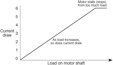
Figure 21-4 All motors draw current; the amount of current depends on the design of the motor and how much load is placed on the motor. As the load increases, so does the current. At some point, the load is too much for the motor and it stops turning, but it still consumes current. This is called the stall current.
You don’t need a lot of speed for most robotic applications. In fact, for DC motors used to move your robot, the speed of the motor needs to be reduced to no more than 200 or 250 RPM—often even slower.
The easiest way to slow down a motor is to attach some gears to it. This also increases the turning force (called torque; see the next section), allowing the motor to push bigger robots or lift heavier objects. Discover more about gears and how they’re used in motors for robots in Chapter 24, “Mounting Motors and Wheels.”
TORQUE
Torque is the force the motor exerts upon its load—the load is whatever it’s moving. The higher the torque, the larger the load can be and the faster the motor will spin. Reduce the torque, and the motor slows down, straining under the workload. Reduce the torque even more, and the load may prove too demanding for the motor. The motor will stall to a grinding halt and, in doing so, eat up current—not to mention, put out a lot of heat.
Torque is perhaps the most confusing design aspect of motors. This is not because there is anything inherently difficult about it, but because motor manufacturers have yet to settle on a standard means of measurement. Motors made for industry are rated one way; motors for the military, another. And most motors for consumer or hobby applications come with no torque ratings at all.
At its most basic level, torque is measured by attaching a lever to the end of the motor shaft and a weight or gauge on the end of that lever, as depicted in Figure 21-5. The lever can be any number of lengths: 1 centimeter, 1 inch, or 1 foot. Remember this, because it plays an important role in torque measurement.
The weight can be either a hunk of lead or, more commonly, a spring-loaded scale, as shown in Figure 21-5. Turn the motor on, and it turns the lever. The amount of weight the motor lifts is its torque. There is more to motor testing than this, of course, but it’ll do for the moment.
Now for the ratings game. Remember the length of the lever? That length is used in the torque specification.
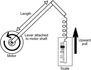
Figure 21-5 The power output or torque of a motor can be measured using a simple graduated spring scale (a fish-weighing scale will do). The motor is attached to the scale using a lever. The amount of pull plus the length of the lever are used to indicate the torque rating of the motor.
![]() If the lever is 1 inch long, and the weight successfully lifted is 2 ounces, then the motor is said to have a torque of 2 ounce-inches, or oz-in. (Some people reverse the “ounce” and “inches” and come up with “inch-ounces.” Whatever.)
If the lever is 1 inch long, and the weight successfully lifted is 2 ounces, then the motor is said to have a torque of 2 ounce-inches, or oz-in. (Some people reverse the “ounce” and “inches” and come up with “inch-ounces.” Whatever.)
![]() Or the torque may be stated in grams, not ounces. In this case, a lever calibrated in centimeters may be used. This gives you grams-centimeter, or gm-cm.
Or the torque may be stated in grams, not ounces. In this case, a lever calibrated in centimeters may be used. This gives you grams-centimeter, or gm-cm.
![]() Torque for very large motors may be rated in pound-feet, or lb-ft.
Torque for very large motors may be rated in pound-feet, or lb-ft.
![]() Becoming more popular is the newton-meter unit of torque, slowly being adopted by motor manufacturers. You may see it as N-m or Nm. One N-m is equal to the torque that results from a force of 1 newton (no, not the fig kind) applied to a lever that is 1 meter long. (If you’re interested, the newton is equal to the amount of force required to accelerate a mass that weighs one kilogram at the rate of 1 meter per second per second.)
Becoming more popular is the newton-meter unit of torque, slowly being adopted by motor manufacturers. You may see it as N-m or Nm. One N-m is equal to the torque that results from a force of 1 newton (no, not the fig kind) applied to a lever that is 1 meter long. (If you’re interested, the newton is equal to the amount of force required to accelerate a mass that weighs one kilogram at the rate of 1 meter per second per second.)
STALL OR RUNNING TORQUE
The typical motor is rated by its running torque— that is, the force it exerts as long as the shaft continues to rotate. For robotic applications, it’s the most important rating because it determines how large the load can be and still guarantee that the motor turns.
Manufacturers use a variety of techniques to measure running torque. The tests are impractical to duplicate in the home shop, unless you have an elaborate dynometer and sundry other tools. Instead, you can empirically determine if the motors are sufficient for the job by constructing a simple test platform, as described in the next section.
Another torque specification, stall torque, is sometimes provided by the manufacturer instead of or in addition to running torque. Stall torque is the force exerted by the motor when the shaft is clamped tight. The motor does not turn.
JUDGING THE TORQUE OF MOTORS
If the motor(s) you are looking at don’t have running torque ratings, you must estimate their relative strength. There are formulas you can use to rate a motor for a specific task, and these have been detailed in numerous books on robotics; try Building Robot Drive Trains (Clark and Owings, McGraw-Hill, 2003). In truth, this is what most people do: they mount the candidate motors on a makeshift platform, attach wheels to them, and have the motors scoot the test bot across the floor. If the motors support the platform, start piling on weights. If the motors continue to operate with the additional load, then you know they’re suitable for the job. (This is called empirical evaluation. It’s how Thomas Edison did most of his inventing.)
You don’t need to build the whole robot just for this test. Employ a temporary construction using lightweight materials, such as heavy-duty cardboard or artists’ foam board. See Chapter 14, “Rapid Prototyping Methods,” for more information. With the techniques outlined in that chapter you can quickly test various motors and robot platform designs.
Such crude tests make more sense if you have a standard by which to judge others. If you’ve designed a robot before and are making another one, you’ll already know what kind of motors work for a robot of a general size and weight.
Testing Current Draw of a Motor
You can often just look at a motor and know it’ll have enough torque for your robot. Less ensured is knowing how much current the motor demands when it’s running. It’s not possible, or even advisable, to infer the current draw of a motor just by its size, shape, or type.
Knowing the current draw is very important: you need to make sure the batteries of your robot have the right capacity and that any electronics you use can handle the current. Should the motors draw too much current, your electronics could overheat and be permanently damaged.
Many motors are provided with a current draw specification. As noted earlier in this chapter, the spec may be the current of the motor when it’s free-running. That’s helpful information, but it’s not enough to know how the motor will behave when it’s pulling weight—or worse, if the motors are loaded down so much they stop turning.
You can use a multimeter to accurately test the current draw of your motor when it’s free-running, under normal load, and even stalled—completely stopped. There are two methods, each described below.
FYI
If you are new to the concept of multimeters, you’ll want to read the manual that comes with yours, and see Chapter 30, “Building Robot Electronics—the Basics,” for more information. What follows assumes you already have at least a basic understanding of how to operate your multimeter.
DIRECT MOTOR CURRENT MEASUREMENT
The steps that follow assume your multimeter has a special input for testing high currents. Many do, and the input is labeled 10A (or similar), like the one in Figure 21-6. It’s a rare motor for a desktop robot that draws more than 10 amps, even when stalled, but even so, check the manual for your meter to be sure the 10A input has a replaceable fuse. (The fuse is usually located in the battery compartment.)
If any of the following are true, skip this section and move to “Indirect Motor Current Measurement.”
![]() My meter does not have a 10A (or higher) input.
My meter does not have a 10A (or higher) input.
![]() My meter doesn’t have an input fuse.
My meter doesn’t have an input fuse.
![]() I suspect the motor may draw current in excess of 10 amps.
I suspect the motor may draw current in excess of 10 amps.
Follow the connection diagram in Figure 21-7. Be sure to connect the red (+, positive) lead of your meter in the 10A socket. Then, connect the test leads to your motor using jumper wires, the kind with heavy-duty alligator clips on the ends. You need two jumpers, one each for the red and black test leads. Then,

Figure 21-6 You may directly measure the current consumption of a motor by using a digital multimeter with a high amperage (10 amps or higher) input.

Figure 21-7 Test the current draw of a motor by interrupting the power line to the motor. Place the + and − leads of the multimeter between this power line, and take the reading. The meter must be dialed to read DC current.
1. Dial the meter to the 10A setting.
2. Apply power to the motor.
3. Observe the reading on the meter. It will be in amps. A reading of 0.30, for example, means 30 mA, or 0.3 of an amp. A reading of 1.75 means 1.75 amps.
This gives you the free-running torque of the motor. For other torque tests, you need to load down the motor.
Small hobby motors without a gearbox can be loaded down just by squeezing the shaft between your fingers. As you slow the motor down, watch the current increase. If you can stop the shaft from turning completely, the motor will be stalled and the current shown in the stall current. That’s about as high as the current will ever get from the motor.
Small hobby motors with a gearbox can be loaded down by applying pressure to the output shaft of the motor or one of the gears in the gearbox nearest the shaft. This, of course, assumes the gears in the gearbox are accessible.

With some gearbox motors you can temporarily remove the motor from the gearbox. Test it alone, then put the motor back into the gearbox.
Larger motors are harder to test just by stopping the shaft with your fingers. It’s better to attach a wheel to the motor (the larger the diameter, the better), then try to apply load to the wheel. Don’t use a pair of pliers or another tool to clamp down on the motor shaft or gears, as this may cause damage. At the very least, you can take the free-running measurement.
INDIRECT MOTOR CURRENT MEASUREMENT
You can still determine current draw from your motors if your multimeter lacks a high current input or if the motor you’re testing draws over 10 amps. The solution is to insert a low-value, high-wattage resistor inline between the + battery terminal and the motor.
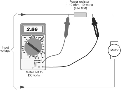
Figure 21-8 An alternative method for testing current draw is to place a low-ohm (1 Ω to 10 Ω) high-wattage resistor inline between the power source and the motor. Change the meter to read voltage. See the text for how to correlate the voltage reading to current.
The value of the resistor can be anything between 1 and 10 ohms, but it needs to be high wattage—10 or 20 watts, even more for motors that draw in excess of 10 amps.
1. Plug the red (+, positive) lead into the standard volts/ohm/current jack.
2. Use jumper clips to insert the resistor into the motor circuit, as shown in Figure 21-8.
3. Dial your multimeter to DC volts. If your meter is not autoranging, select a voltage at or just higher than the voltage you will apply to the motor.
4. Connect the red (+, positive) lead of your multimeter to the side of the resistor closest to the voltage source.
5. Connect the black (−, negative) lead of your multimeter to the other side of the resistor.
6. Apply power to the motor.
What you’ll see is the voltage developed across the resistor. You then use one of the simple formulas of Ohm’s law to determine the current flowing through the resistor. The formula is
I = E/R
where I is current, E is voltage, and R is resistance.
You are solving for I, or current, because you know the voltage developed across the resistor and you know the value of the resistor, in ohms. Let’s suppose:
![]() The measured voltage is 2.86, and
The measured voltage is 2.86, and
![]() The resistor is rated at 10 ohms.
The resistor is rated at 10 ohms.
I = 2.86/10
or
I = 0.286, or 286 milliamps
Watch the voltage go up as you apply load to the motor shaft. See the previous section on how to test for currents under load and when stalled, using nongeared and geared motors.
Dealing with Voltage Drops
On most robots it’s the motors that draw the most current. As the motors stop and start, the voltage provided to them can change. This happens because under heavy current draw, the voltage provided by the batteries can momentarily sag. The sag may be for only a fraction of a second, but it can be long enough to cause problems.
If your robot’s control computer is connected to the same battery source as the motors, the voltage drop can cause what’s known as a brownout; if the brownout causes the voltage to drop below a certain threshold (Figure 21-9), the control electronics may not operate correctly. Quite literally, your robot can go berserk!
Brownouts are particularly troublesome when using microcontrollers (see Part 7), which are small computers that run a program you devised. During a brownout, the microcontroller may spontaneously reset, causing it to rerun its programming from the beginning. This can actually occur several dozens or even hundreds of times a second.
During these brownouts your robot may become inactive (that’s good), or it may lurch or spin or do something else unpredictable (that’s bad).
There are several ways of avoiding voltage drops caused by motors:
![]() Add more volts to your robot’s batteries. If the batteries normally supply 6 volts, but may “sag” to 4.5 volts during heavy motor draw, add another cell to bring the voltage to 7.2 or 7.5. The extra margin might prevent a voltage sag that causes a brownout.
Add more volts to your robot’s batteries. If the batteries normally supply 6 volts, but may “sag” to 4.5 volts during heavy motor draw, add another cell to bring the voltage to 7.2 or 7.5. The extra margin might prevent a voltage sag that causes a brownout.
![]() Add bigger batteries with a higher capacity (amp hours). The volts may be the same, but the added current capability can provide a reserve against voltage drops.
Add bigger batteries with a higher capacity (amp hours). The volts may be the same, but the added current capability can provide a reserve against voltage drops.
![]() Add a second battery pack to operate the electronics. This is my preferred method, because it effectively isolates the power supplies for the motor and electronics. As the motors draw current, they pull it from their own batteries and not from the pack powering the electronics.
Add a second battery pack to operate the electronics. This is my preferred method, because it effectively isolates the power supplies for the motor and electronics. As the motors draw current, they pull it from their own batteries and not from the pack powering the electronics.
For small robots you can often use a AAA-to D-size battery pack for the motors, and a 9-volt battery for the robot control electronics. If you have lots of electronics—microcontroller, multiple sensors, maybe a video camera—you might need to beef up the second battery. Use a separate multicell battery pack selected to provide the current needed for the electronics.
In order for the dual power supply technique to work, the ground (−, negative) lead from both battery packs must be connected together. This topic is discussed in more detail in Chapter 22.
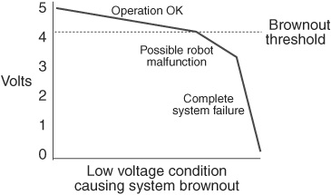
Figure 21-9 A brownout may occur when the system voltage of your robot falls below a certain minimum level. As the voltage falls under the brownout threshold, operation of the robot becomes unpredictable.
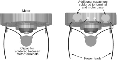
Figure 21-10 Electrical noise generated inside a DC motor can affect the operation of robot electronics. This noise can be suppressed by using small ceramic disc capacitors (0.01 to 0.1 μF) soldered to the motor terminals as shown.
Avoiding Electrical Noise
Electric motors generate lots of noise. In one form, the noise is like the static of a thunderstorm on an AM radio. It doesn’t matter that the lightning bolt is miles away; the electrical charge travels through the atmosphere and into the radio’s circuits, ending up as a loud snap, crackle, and pop in the speaker.
Fortunately, it’s rather easy to cut down on the electrical noise produced by your robot’s motors. The solution is to place one or more capacitors as near to the motor terminals as possible. The capacitor literally “soaks” up the electrical transients produced by the motors, which in turn reduces the noise they make.
![]() As part of good operating procedure, place a 0.1 μF ceramic disc capacitor across the motor terminals. Just solder the sucker right in there, along with the power leads to the motor.
As part of good operating procedure, place a 0.1 μF ceramic disc capacitor across the motor terminals. Just solder the sucker right in there, along with the power leads to the motor.
![]() If the motor still generates too much electrical noise for the circuit, then as an extra precaution solder a 0.1 μF ceramic disc capacitor from each power terminal to the metal case of the motor. (This can be a bit tricky. To get the solder to stick to the motor case be sure it’s clean. Rough up the metal with a small file. If needed, dab on some solder flux paste over the area and turn up the head of the soldering tool.)
If the motor still generates too much electrical noise for the circuit, then as an extra precaution solder a 0.1 μF ceramic disc capacitor from each power terminal to the metal case of the motor. (This can be a bit tricky. To get the solder to stick to the motor case be sure it’s clean. Rough up the metal with a small file. If needed, dab on some solder flux paste over the area and turn up the head of the soldering tool.)
Figure 21-10 shows the idea. The added capacitor(s) act to filter out the electrical noise from the motor, helping to reduce the amount of noise that travels back to the circuit.