Chapter 10
Build a Motorized Plastic Platform
This chapter details construction of the PlastoBot, the base for a small but peppy robot that’s constructed using 1/8″-thick plastic—most any plastic will do, so if you already have a piece in your garage feel free to use it. I built the prototype PlastoBot using 3mm (about 1/8″) expanded PVC.
PlastoBot is basically a square, and making it involves only straight cuts. The corners of the plastic are chamfered—lopped off at a 45° angle—to enhance the looks and to prevent the base from snagging on things. You can build the robot with or without cutouts for the wheels. The cutouts can be tricky to make, but they allow the robot to retain its sleek design by keeping the wheels inside the profile of the base.
The PlastoBot as described here is 4″ square, but the design is scalable. As desired, you can make it larger … or smaller, if you have teeny-tiny motors and wheels. The practical maximum is about 10″ square. For any base larger than 5″ or 6″ you should double the thickness of the plastic—from 1/8″ to 1/4″.

I provide the exact model number for each of the pieces you need, but remember that you’re free to substitute parts for others if you already have them or if you’ve found substitutes that are cheaper or easier to get.
Making the Base
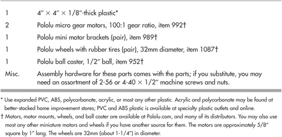
Refer to Table 10-1 for a list of parts.
Figure 10-1 shows the completed PlastoBot. It measures 4″ square and is balanced on one end with a small plastic ball caster. (If you don’t want to use a ball caster, you can provide the bot with a static skid, using an 8-32″ × 1″ machine screw and acorn nut. See the end of Chapter 8 for a quick description of the idea.)
Table 10-1 PlastoBot Parts List
While the plans call for 1/8″ plastic, you may use another thickness if that’s what you have. For reasons of weight, you’ll want to avoid using a dense plastic (acrylic or polycarbonate) if it’s over 3/16″ or so. The thicker plastic is also harder to cut and drill.
Begin with a 4″ by 4″ square, and lop off the corners. How much material you remove is up to you, but a 1/2″ chamfer is sufficient—to measure this amount, just make a set of marks 1/2″ from each corner, and cut a 45° diagonal across the marks.
The PlastoBot design calls for rectangular cutouts for the wheels—what I refer to as wheel wells. For the wheels specified (see Table 10-1), the cutouts measure 1-3/8″ by 1/2″; both are placed centerline in the base. Refer to Figure 10-2 for a guide. You can see the benefit of the cutouts in Figure 10-3, which shows the differences in the profile of the robot, given wheels on the outside of the base versus wheels within the area of the base.
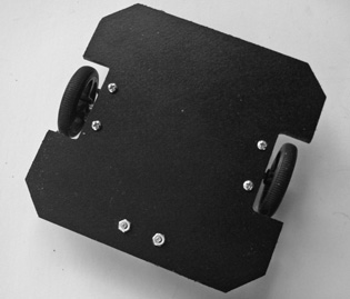
Figure 10-1 The finished PlastoBot, using two micro motors, wheels, and a small plastic ball caster for balance. The robot measures 4″ square.
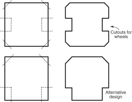
Figure 10-2 The base of the PlastoBot uses chamfered corners and cutouts for the wheels. You may elect to place the wheels centerline (preferred) or at one end of the base.
Also shown in Figure 10-2 is an alternative design for the PlastoBot, where the wheels are located at one end of the base. This style is a bit easier to make, because it doesn’t require an elaborate internal cut for the wheel wells. As with the centerline wheel wells, make these cutouts 1-3/8″ by 1/2″.
Attaching the Motors
The PlastoBot uses a pair of micro-miniature motors, shown in Figure 10-4. These are highly precise motors that use metal gears, yet their price isn’t much more than most other small motors for robotics.
The motors I selected are sold online through Pololu.com, as are the plastic mounts for attaching the motors to the base. Also provided by them are the wheels and the plastic ball caster described below. The same or similar motors and wheels are available at other robotics specialty stores; see Appendix B, “Internet Parts Sources” for more information. (In many cases these other stores resell the Pololu products, and in other cases, they offer competing merchandise.)

Figure 10-3 The effect of having wheels outboard of the base and inboard. When inboard, the shape of the robot is more streamlined, and it’s less likely to snare on objects it encounters.
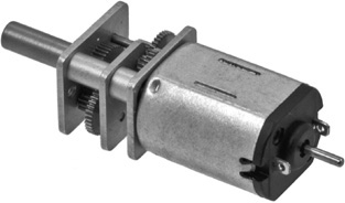
Figure 10-4 Metal gear micro motor. Two are used in the PlastoBot. (Photo courtesy Pololu.)
The micro motors measure 0.94″ by 0.39″ by 0.47″, and have a 3/8″-long 3mm D-shaped shaft that directly couples to the specified wheels. The motors are too small to have a mounting flange to directly attach them to the base, but brackets are available that make the job a cinch.
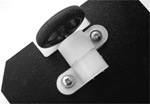
Follow the drilling guide in Figure 10-5. The spacing of the holes requires a modest amount of accuracy, so measure twice. The brackets have two holes spaced 18mm (about 11/16″) apart, and they come with their own miniature 2-56″ steel machine screws and nuts. The nut fits into a shaped recess inside the bracket; the screw comes up through the base to secure the motor in place (see Figure 10-6). For now just finger-tighten the screws.
Both the motor brackets and the ball caster use millimeter sizes. I’ve included the spacings in both millimeters and the closest fractional inch, accurate to 1/16″.
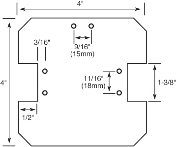
Figure 10-5 Drilling layout for the PlastoBot. The horizontal position of the two sets of holes for mounting the motors is not super critical, but the vertical spacing of the holes must be reasonably accurate. They must match the hole spacing of the motor mounts.

Figure 10-6 Mounting the motors using the specialty mounts. Miniature 2-56 fasteners come with the mounts and are inserted as shown.
Fitting the Wheels
PlastoBot’s wheels are molded plastic with a removable rubber tire. The wheels are available in a variety of sizes, and I’ve picked one of the smallest, because of the diminutive stature of the robot. If you scale up the PlastoBot to bigger dimensions you’ll probably want to opt for a larger wheel—the 80mm or 90mm wheels can be used for bases three and four times the size of PlastoBot.
To fit the wheels, merely press them into place over the motor shaft. The wheels have a D-shaped hub, matching the flatted shaft of the motors.
Once the wheels are in place, slide the motor into the bracket, adjust the position of each motor so the wheels are the same distance from the base, and tighten the two screws until the motor is snug.
Attaching the Ball Caster
The support caster uses a 1/2″ plastic ball (see Figure 10-7), which smoothly rotates inside a cavity. Like the motor brackets, the ball caster comes with its own 2-56 fasteners. It also comes with several plastic spacers; use the thicker of the two spacers to increase the height of the caster to better match the diameter of the PlastoBot’s wheels. The screws must be inserted so that the head fits into the body of the case. Position the nuts on the top side of the base.
Figure 10-8 shows the underside of the PlastoBot, with caster, motors, and wheels attached.
Using the PlastoBot
The PlastoBot uses high-efficiency micro motors that operate at between 3 and 9 volts, with 6 volts being nominal (normal). You can rig them up to switches to manually control the motor (on/off and direction) or use electronic control. These topics are covered in Chapter 22, “Using DC Motors.”
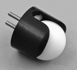
Figure 10-7 Miniature ball caster, with 1/2″ plastic ball. The ball rotates against small rollers inside the caster body. (Photo courtesy Pololu.)
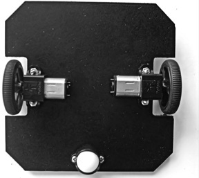
Figure 10-8 Underside of the PlastoBot, showing motors in their mounts and the ball caster.
These motors draw low current for the torque (turning power) they provide, allowing you to use most any kind of electronic control. When free-running (no load), the motors consume only 40 milliamps; at stall (the motors are physically prevented from turning), current rises to a still-respectable 360 milliamps. The low current demand of the motors lets you pick from a wide variety of motor drive circuits.
FYI
See Chapter 21, “Choosing the Right Motor,” for more on motor torque, milliamps, current measurements, voltage, and other motorific specifications.
If you’ve built the centerline wheels version of the PlastoBot, be mindful of maintaining a weight balance that slightly favors the end with the ball caster. This prevents the robot from tipping over on the end without the caster.
Altering the PlastoBot Design
Feel free to experiment with the design of the PlastoBot base. For example, by increasing the chamfer, you can make an octagonal base. Just cut off more of each corner.
You can also fashion your own motor mounts using standard fasteners and strips of flexible plastic. Figure 10-9 shows an octagonal PlastoBot base with holes for mounting motors up to about 1″ wide. The idea for the mounts is shown in Figure 10-10: drill two holes just wider than the width of the motor. Using machine screws and nuts, attach a strip of flexible plastic to the top. Tighten the screw against the bottom nut to hold the motor in place.
Candidate plastic includes pieces stolen from construction toys, clamps for cable and wire management, and household odds and ends. The basic requirement (besides being the right approximate size and shape) is that the plastic be flexible. As you tighten the screw against the body of the motor, you want the plastic to deform, in order to hold the motor in place.
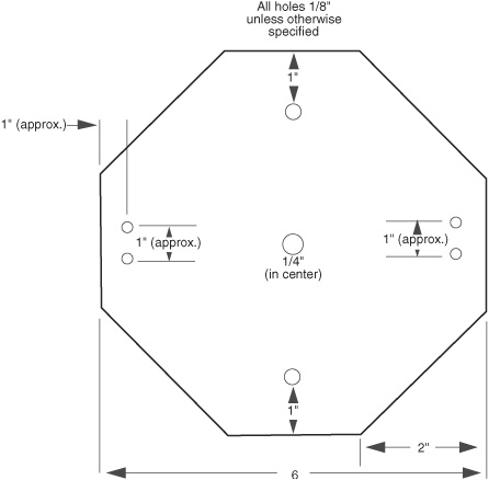
Figure 10-9 One of many alternative base designs for a robot made of plastic. A hexagonal base may be constructed by cutting off the four corners of a square.
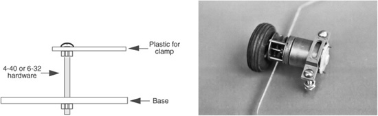
Figure 10-10 Ways to mount a motor using simple hardware and a flexible plastic strap. The technique works for motors with square or round cases.
Another approach to homemade motor brackets is to use small cable management clamps. The Pololu micro motors used in the PlastoBot fit snugly in 1/2″ clamps. You need two, positioned opposite one another to hold the motor in place. The clamp around the gearbox secures the motor in place, and the clamp around the body keeps the motor from shifting around on the base.