
Chapter 42
Adding the Sense of Touch
A sure way to detect objects is to make physical contact with them. Contact is the most common form of object detection, and it’s also the cheapest to implement—often with just an inexpensive switch. Touch sensing can be used on the base of a robot for when it’s crisscrossing the living room carpet, or on arms and grippers, to detect when objects have been grasped or even when they’re about to be crushed to smithereens.
This chapter deals with touch-sensing systems, whether it’s a simple switch on the back of the bot so it knows when it’s bumped into something, or artificial “skin” that detects the amount of pressure applied to it.

This chapter deals only with “touch,” your robot making actual contact with something. Other principal forms of robotic sensing are proximity detection and distance measurement. These are used to detect objects before your robot bounces into them. Read more about proximity and distance sensing in Chapter 43.
![]()
Source code for all software examples may be found at the RBB Online Support site. See Appendix A, “RBB Online Support,” for more details. To save page space, the lengthier programs are not printed here. The support site also offers source code with added comments, parts lists (with sources) for projects, updates, extended construction plans, and more examples you can try!
Understanding Touch
Touch, also called tactile feedback, is a reactive event. The robot determines its environment by making physical contact; this contact is registered through a variety of touch sensors. Most often, a collision with an object is a cause for alarm, so the reaction of the robot is to stop what it’s doing and back away from the condition.
But in other cases, contact can mean the robot has found its home base, or that it’s located an enemy bot that is about to pound the living batteries out of it. For the typical robot, touch is reduced to sensing only mechanical pressure.
Because robotic touch is based on pressure, the amount of pressure dictates how sensitive the robot is. A large mechanical switch that requires a great deal of force to actuate will be insensitive to routine contact. In order for the switch to activate, it may require a forceful collision with an object.
Conversely, a lightweight wire that is actuated by a slight sideways pressure may be activated by a gentle nudge. You can tailor your robot’s contact sensitivity by altering the type and size of its touch detectors.
Mechanical Switch
The lowly mechanical switch is the most common, and simplest, form of tactile (touch) feedback. Just about any momentary, spring-loaded switch will do (see Figure 42-1). When the robot makes contact, the switch closes, completing a circuit—or in some cases, the switch opens, breaking the circuit. Either way works.
The switch may be directly connected to a motor, or, more commonly, it may be connected to a microcontroller or other electronic circuit. A typical wiring diagram for the switch is shown in Figure 42-1. The pull-down resistor is there to provide a consistent LOW output for the switch when there is no contact. When contact is made, the switch closes, and the output of the switch goes HIGH.
When using a microcontroller, you can determine how the robot reacts to the physical collision by altering its programming. Typically, for a switch used for a touch sensor, the programming instructs the robot to stop, back up, and head in a new direction.
PHYSICAL CONTACT BUMPER SWITCH
You can choose from a wide variety of switch styles when designing contact switches for tactile feedback. A leaf or lever switch (sometimes referred to as a Microswitch, after a popular brand name) comes with plastic or metal strips of different lengths that enhance the sensitivity of the switch. See Figure 42-2 for an example of a lever switch ideal for use as a contact bumper for a small robot.
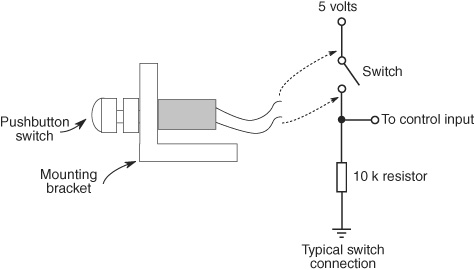
Figure 42-1 Mechanical and electrical connection of a momentary (spring-loaded) push-button switch. The 10 kΩ resistor ensures that the output is LOW until the switch closes.
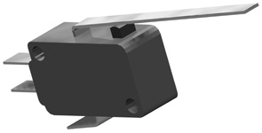
Figure 42-2 Leaf or lever switches make for ideal bumpers for robotics. You can choose from among switches with a long or a short leaf.

Leaf switches require only a small touch before they trigger. The plunger in a leaf switch is extra small and travels only a few fractions of an inch before its contacts close. As the leaf is really a mechanical lever, lengthening it increases sensitivity. But it also increases the distance (called throw) that the end of the lever must travel before the switch makes contact.
ENLARGING THE CONTACT AREA OF THE SWITCH
The surface area of most switches is pretty small. You can enlarge the contact area by attaching a metal or plastic plate or a length of wire to the switch plunger. A piece of rigid 1/16″-thick plastic or aluminum is a good choice for bumper plates. Glue the plate onto the plunger.
Low-cost push-button switches are not known for their sensitivity. The robot may have to crash into an object with a fair amount of force before the switch makes positive contact, and for most applications that’s obviously not desirable. You’re better off spending a little more for higher-quality switches.
For a leaf switch, you can mount a plastic or metal plate to the end of the leaf to increase surface area. If the leaf is wide enough, you can use miniature 4-40 machine screws and nuts to mount the plate in place.
EXTENSION WHISKER
The whiskers of a cat help its brain form a 3D topographical map of the animal’s surroundings. At its most simplistic level, the whiskers can be used to measure space. We can apply a similar technique to our robot designs—whether or not kitty whiskers are actually used for this purpose.
You can use thin 20- to 25-gauge piano (“music”) wire for the whiskers of the robot. Attach the wires to the ends of switches, or mount them in a receptacle so the wires are supported by a small rubber grommet.
By bending the whiskers, you can extend their usefulness and application. The whiskers in Figure 42-3 make contact with a small (and sensitive) leaf switch. You can cement or tape the wire to the switch, and bend the wire to make a whisker of the size and shape you want. When the switch and whiskers are positioned so they detect vertical motion, they can determine changes in topography to watch for such things as the edge of a table or the corner of a rug.

Figure 42-3 Use piano (music) wire or small rigid tubing to extend the length of a leaf switch. Use glue or tape to hold the wire in place.
![]()
You want to avoid sharp wires sticking out of your robot. Not only can they snag on objects, they can poke at skin, eyeballs, and other sensitive body parts of humans and animals. Bend the ends of the whiskers or other wires to form a small blunted loop. If the wires are heavy enough, insert a rubber stopper, like that used for knitting needles (also called point protectors). The stoppers come in several sizes.
SPRING WHISKER
You can make your own switches using stiff wire and a spring. One approach is shown in Figure 42-4. Use a long wire and a short spring, both mounted on a perforated circuit board. The two pieces form a switch circuit: when the wire bends, it touches the spring, which signals contact. It’s important that the spring is held concentric around the wire. The spring should touch the wire only upon contact. The larger the diameter of the spring, the less sensitive the switch.
You can also reverse the concept: use one narrow spring nested inside a larger spring. For the larger spring you can substitute stiff wire with a wide loop bent at the end. When the spring touches the loop, the switch is closed.
HOMEBREW CONTACT WHISKER
With some stiff music wire, you can build your own contact whiskers and form them into any shape you like. Figure 42-5 shows the basic idea of two wire whiskers for a robot. Both designs are made directly on an experimenter’s solderboard (don’t use a solderless breadboard).
![]() In Style A, the wire goes between three male header pins, where the middle pin of the three has been cut off. The whisker makes contact with any side-to-side movement. If the fit between the pins is too small, use instead a set of four male header pins and cut off the middle two.
In Style A, the wire goes between three male header pins, where the middle pin of the three has been cut off. The whisker makes contact with any side-to-side movement. If the fit between the pins is too small, use instead a set of four male header pins and cut off the middle two.
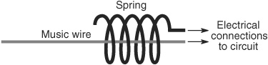
Figure 42-4 Spring-and-wire homemade whisker switch. When the wire makes contact with the spring, the circuit is closed.
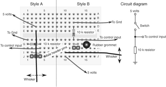
Figure 42-5 Plan view of two ways to implement the electronics of homebrew whisker switches. The one on the left is most sensitive to side-to-side motion; the one on the right, back-and-forth motion. See the text for how to use the male header pins as whisker contacts.
![]() In Style B, the wire goes in front of a series of male header pins. I’m also using an additional pin outfitted with a rubber grommet; it acts as a backstop. You can add more pins and connect them all together electrically if you want more contact area.
In Style B, the wire goes in front of a series of male header pins. I’m also using an additional pin outfitted with a rubber grommet; it acts as a backstop. You can add more pins and connect them all together electrically if you want more contact area.
Both styles show the stiff wire connected directly to the electrical contacts of the solder-board. In order to solder this connection, the wire should be copper or brass; metals like stainless steel are harder to solder. You should apply a soldering iron or pencil with a higher wattage than you’d normally use for electronics. Solder the wire connections first, before adding the other components.
Figure 42-5 shows the typical electrical connection of the whisker to your control electronics. It works the same as any switch, so the working concept is the same. The control input is a microcontroller I/O line, a connection to a motor, and so forth.
Avoid damage or injury by adding a small loop at the outside end of the whisker. This prevents the wire from poking into ankles, eyeballs, and antique furniture legs.
![]()
MULTIPLE BUMPER SWITCHES
What happens when you have many switches scattered around the periphery of your robot? You could connect the output of each switch to your microcontroller, but that’s a waste of I/O pins. A better way to do it is to use a priority encoder, a multiplexer, or a parallel-in, serial-out (PISO) IC.
All three schemes allow you to connect several switches to a common control circuit. The robot’s controller gets the switch information from the control circuit instead of from the individual switches.
Using a Priority Encoder
The circuit in Figure 42-6 uses a 74148 family IC (such as the 74HC148) priority encoder IC. Switches are shown at the inputs of the chip. When a switch is closed, its binary equivalent appears at the A-B-C output pins. With a priority encoder, only the switch that represents the most significant bit is indicated at the output (pin 4 is the most significant bit; pin 10 the least significant bit).
In other words, if switches connected to pins 4 and 1 are both closed, the output will reflect only the closure of switch 4, as 4 has a higher priority. Sometimes this is useful information (some bumper switches are more important than others); sometimes it’s not. When it’s not, use one of the other approaches discussed next.
When using a 74148 chip with fewer than eight switches, be sure to tie any unused inputs HIGH. Connect the switches in descending significant order: 4, 3, 2, 1, 13, 12, 11, 10.
Back up the truck a bit before going on. The 74148 has an interesting feature you might not want to miss. Notice pins 14 and 15. These are “group” outputs, meaning their state changes when any of the switches are closed. You can use this feature with a microcontroller that has a hardware interrupt pin (like the Arduino).
If any of the eight switches close, the group output can signal the interrupt. The microcontroller can then check the A-B-C output lines to see which switch is closed (if more than one switch is closed, the most significant switch is indicated). Use this feature when your microcontroller has only a few hardware interrupt pins and your robot has a lot of switches.
There are methods of cascading (daisy-chaining) priority encoders, so you can check 16 or more switches. See the datasheet for the 74148 chip for ideas.
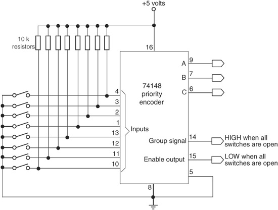
Figure 42-6 A priority encoder IC tells you the value of the most significant bit in a field of 8 bits. The 10 kΩ resistors are used as pull-ups for the switches.
Using a Multiplexer
Another method is shown in Figure 42-7. Here, a 74151 family multiplexer IC (such as the 74HC151) is used as a switch selector. To read whether a switch is set or not, the microcontroller or computer applies a binary weighted number to the three input select pins. The state of the desired input is provided at the Output pin (pin 5). The advantage of the 74151 is that the state of any switch can be read at any time, even if several switches are closed.
Here’s the truth table for the 74151. The A-B-C input select pins control which of the eight input lines appears at the Output pin.
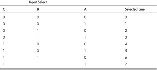
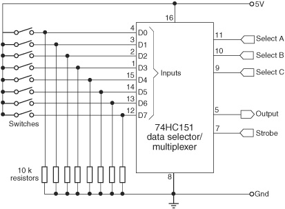
Figure 42-7 The 74151 multiplexer IC will tell you the instantaneous value of any of eight switches. You set the switch to read with the three Input Select pins.
The switch_mux.pde sketch, for the Arduino microcontroller, provides a quick example of reading a single 74151 chip, connected to eight bumper switches. Open the Serial Monitor window to see the bit pattern of the switch states: 0 means the switch is open; 1 means it’s closed. The 8 bits are ordered left to right from D0 to D7.

switch_mux.pde
To save space, the program code for this project is found on the RBB Online Support site. See Appendix A, “RBB Online Support,” for more details.
Okay, so you’re probably wondering: why the big deal over saving a measly three I/O pins? It takes five pins to work the 74151 chip, which reads just eight switches.
The secret is that you can use the simple polling technique with multiple ’151 ICs. All of the chips can share the same Select and Strobe lines. For each 74151, you connect a separate Output to the microcontroller
Suppose you want to track 24 switches. That takes three 74151 ICs, and a total of seven I/O lines: four for the A-B-C Select and Strobe pins, and three for the Output line of each of the chips. All three ‘151 multiplexers send back their output at the same time. Each output represents a group of eight switches.
Using a PISO IC
PISO stands for parallel-in, serial-out: you apply a set of values in parallel and the circuit converts it to a simple serial data train. A PISO (also called shift register) chip, like the 74HC165, gives you eight switch inputs, as shown in Figure 42-8. The instantaneous value of any switch is reflected in the serial output.
PISO (and its inverse, the SIPO) shift registers are covered in more detail in Chapter 40, “Interfacing Hardware with Your Microcontroller or Computer.” Basically, you connect the Clock, Data, and Latch pins of the PISO to your microcontroller. Program switch_piso.pde, for the Arduino, shows how to read the parallel bits on a 74HC165 parallel-in, serial-out shift register IC and display the current values in the Serial Monitor window. Note that while I have specified the HC type for this chip, you can use any in the 74165 family, such as the HCT or LS.
Figure 42-8 The 74HC165 shift register takes the value of eight switches, and provides a single stream of serial data.
![]() Momentarily set the latch pin HIGH to read in the eight switches.
Momentarily set the latch pin HIGH to read in the eight switches.
![]() Set the latch pin LOW to begin reading the serial data.
Set the latch pin LOW to begin reading the serial data.
![]() Pulse the clock pin eight times (for eight switches), while reading the LOW and HIGH values coming in over the data pin.
Pulse the clock pin eight times (for eight switches), while reading the LOW and HIGH values coming in over the data pin.
The switch settings are shown in binary form in the Serial Monitor window, where 0 means the switch is open and 1 means it’s closed. For example,
01110001
means the number 2, 3, 4, and 8 switches are closed. The bits are in D0 to D7 order.
switch_piso.pde
To save space, the program code for this project is found on the RBB Online Support site. See Appendix A, “RBB Online Support,” for more details. You’ll also find a version combining two shift register chips, in order to read up to 16 switches at a time.
In the switch_piso.pde program, the switch states are stored as 8-bit values in the data-Store variable. Use this variable for any additional processing. If dataStore > 0, then you know at least one switch is closed. You can use the Arduino getBit statement to determine which switch (or switches) is closed, and act upon it accordingly.
The 74165 reads up to eight switches, but you don’t always have to use that many. Wire up the switches you want, starting with D0 (pin 11). Don’t leave an unused input pin dangling; connect it directly to ground. That keeps the pin from floating (giving possibly bogus results), which appears as nonsense data.
Using a Button Debounce Circuit
Bounce is what happens when the contacts in a switch open or close. The contacts don’t just immediately open or close once when the switch is pushed. There may be dozens of “tentative” opens and closes each time the switch changes state. The bounces are a kind of electrical noise that can influence the operation of your circuits and programming.
There are numerous ways to remove the extra bounces when a switch opens or closes. They all operate on the principle of stretching the duration of the first switch event that occurs. Most bounces are less than 10 or 20 milliseconds (often much shorter than that, depending on the switch); by stretching out the switch change, all the other bounces that come after are simply missed.
Figure 42-9 shows a common approach to hardware button debouncing. It uses one-sixth of a 74HC14 Schmitt trigger inverter IC, along with a resistor and capacitor to form an RC timing network. Note that the 74HC14 contains inverting buffers, meaning that the polarity of the input signal is reversed on the output—LOW becomes HIGH, and HIGH becomes LOW. Remember this when you connect your circuit to your microcontroller. (If you really, really hate this aspect, and you have inverters to spare, connect two in daisy-chain fashion. This method inverts that which was inverted, and you’re back to life as usual.)
Schmitt triggers do their magic because their output is either LOW or HIGH. There are never any in-between voltages, which can occur because of the introduction of the capacitor in the switch network. The capacitor changes the switch transitions from sharp cliffs to gradual slopes (doing so masks the bounces), and the gradual slopes can cause your microcontroller to confuse what is and isn’t a proper LOW or HIGH. The Schmitt trigger eliminates this problem.
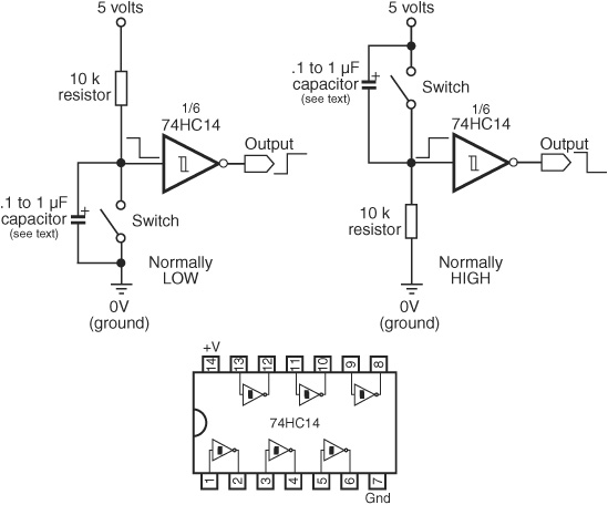
Figure 42-9 Switch debouncer built around a Schmitt inverter buffer. The 7414 IC has six Schmitt inverters in it. Vary the value of the capacitor (from about .1 to 1 μF) for a longer or shorter pulse output. Higher values produce longer delays and are useful with really dirty (electrically speaking) switches.
![]()
You can implement switch debouncing in many different ways. Check out the RBB Online Support site for several additional methods, including using an LM555 timer IC to literally “stretch out” the pulse. This circuit is useful for debouncing, and to make even the most fleeting switch contact last longer. That can be handy when programming, to keep your microcontroller or other circuit from missing the switch action.
Debouncing Switches in Software
Most or all of the functionality of a debouncer circuit can be built in software—good when you’re already using a microcontroller or computer for your robot’s brain. Like the capacitor, the software technique uses delays to momentarily slow down the program when the first switch transition occurs.
Most microcontrollers have programming statements that provide debounce delays, saving you the hassle of adding the code yourself. The Arduino has available a Bounce library that you can download and add to your sketches. The PICAXE and the BASIC Stamp support the button statement which includes a parameter for specifying a delay period. Use these whenever you find it necessary to debounce a switch.
Programming for Bumper Contacts
Bumper switches and other forms of touch produce what’s known as transitory events: they may not occur for long periods of time, and when they do, they may not last long. When using a microcontroller, you need to program it to watch for these events, so that your robot can take the appropriate action when contact is made.
There are three general approaches for programming a microcontroller for bumper contacts and other events of short duration: preemptive wait, polled, and interrupt.
![]() Preemptive waiting involves using a command of your microcontroller to continuously check the state of a single switch or other transitory input. Because of how preemptive waiting works, the microcontroller is not able to perform other parts of its regular program.
Preemptive waiting involves using a command of your microcontroller to continuously check the state of a single switch or other transitory input. Because of how preemptive waiting works, the microcontroller is not able to perform other parts of its regular program.
![]() Polling involves periodically checking the state of any switches or other transient event sensors in your robot, while allowing the rest of your program to run. Because most microcontrollers are quite fast compared to the various functions of your robots, this is often a perfectly acceptable approach. As part of the main program code, your robot checks each switch in turn, testing whether the switch has been activated.
Polling involves periodically checking the state of any switches or other transient event sensors in your robot, while allowing the rest of your program to run. Because most microcontrollers are quite fast compared to the various functions of your robots, this is often a perfectly acceptable approach. As part of the main program code, your robot checks each switch in turn, testing whether the switch has been activated.
![]() Interrupts are handled internally by the microcontroller, and trigger by themselves. Your software need only read the interrupt, telling the microcontroller what you want to have happen when it’s triggered. When an event occurs, the interrupt momentarily stops the regular program and performs whatever special task you’ve set up.
Interrupts are handled internally by the microcontroller, and trigger by themselves. Your software need only read the interrupt, telling the microcontroller what you want to have happen when it’s triggered. When an event occurs, the interrupt momentarily stops the regular program and performs whatever special task you’ve set up.
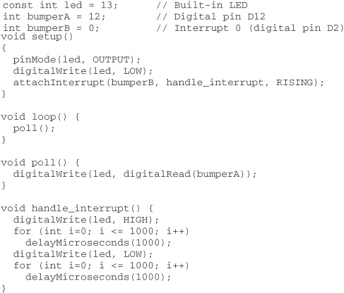
Program button-press.pde shows how polling and interrupts are handled on the Arduino. To simplify things, only two switches are used; one is polled, and the other is set up for an interrupt. Two of the digital input pins on the Arduino may be used as hardware interrupts. Depending on the exact model of the Arduino hardware you are using, this is usually pins D2 and D3. To try this program, connect one switch to pin D12 and another to D2.
The program sets up pin D13, which has an integrated LED already on it, as an output. It also attaches an interrupt to watch for any change on pin D2 (known as interrupt 0). Ordinarily, the LED shows the value of the switch on D12. It’s off if the switch is open, on if the switch is closed. This is handled by the poll routine.
When the switch connected to D2 opens or closes, the microcontroller immediately branches to the handle_interrupt routine, which blinks the LED on and off for 1 second. After the handle_interrupt routine is finished, the regular program resumes.
This example also demonstrates that when the Arduino is “servicing” the interrupt, the other parts of the code aren’t executed. This is by design. Only when the interrupt is finished does program execution pick up where it left off. Normally you wouldn’t have such long delays in your interrupt routines.
Also notice I used the delayMicroseconds statement, rather than delay. Why? The delay statement uses some internal interrupts of the Arduino, so it’s disabled while in an interrupt handler. If you want a delay, you need to use delayMicroseconds. The for loop is used to extend the delayed time in 1-millisecond (1000-microsecond) increments.
button_press.pde
![]()
See the RBB Online Support site (refer to Appendix A) for an extended version of this code, with enhanced comments. The extended version is coupled with controlling two motors, to demonstrate a touch-reactive robot.
Mechanical Pressure Sensors
A switch is a go/no-go device that can detect only the presence of an object, not the amount of pressure on it. A pressure-sensitive detector senses the force exerted by the object onto the robot, or vice versa—how hard the robot has crashed into something.
There are a number of pressure-sensitive detectors you can use in your robots. Some you can make, some you can steal from old parts, and yet others are available as specialty sensors, available from numerous online sources.
ANTISTATIC CONDUCTIVE FOAM
You can make your own pressure-sensitive detector (or transducer, if you like fancy terms) out of a piece of discarded conductive foam—the stuff used to package static-sensitive integrated circuits. The foam is like a resistor. Attach two pieces of wire to either end of a 1″ square hunk and you get a resistance reading on your volt-ohm meter. Press down on the foam and the resistance changes.
The foam comes in many thicknesses and densities. I’ve had the best luck with the semistiff foam that bounces back to shape quickly after it’s squeezed. Very dense foams have a cellular structure that is not as useful because it doesn’t quickly spring back to shape. Save the foam from the various ICs you buy and test other types until you find the right stuff for you.
Experimenting with a Basic Pressure-Resistive Pad
Here’s how to make a “down-and-dirty” pressure sensor for basic testing purposes. Cut a piece of foam 1/4″ wide by 1″ long. Attach leads to it using 30-gauge wire-wrapping wire. Wrap the wire through the foam in several places to ensure a good connection, then apply a dab of solder to the wires to keep everything in place.
Connect the leads of the pad to a multimeter. If the meter is not autoranging, select a midway value of about 200 kΩ. Place the pad on a hard surface like your worktable, and then slowly press down on it with your finger. Watch the resistance value drop. Release your finger and watch it climb back up.
Enhancing the Pressure Pad
Once you’ve seen how conductive foam behaves, you’re ready to make a better sensor by sandwiching several pieces of material together, as depicted in Figure 42-10. The conductive foam is placed between two very thin sheets of copper foil, which you can get at most any craft or hobby store. A short piece of 30-AWG wire-wrapping wire is lightly soldered onto the foil; or you can use conductive glue, which you can get from many sources online (just do a Web search).
Mylar plastic, like the kind used to make heavy-duty garbage bags, is glued on the outside of the sensor to provide electrical insulation, though this part is optional. Use a glue stick for the adhesive.
Variations in Readings
The output of the foam transducer changes abruptly when it is pressed in. The output may not return to its original resistance value (see Figure 42-11). So in your control software, you should always reset the transducer just prior to grasping an object.
For example, suppose you’re using conductive foam in a robotic gripper. Without any pressure on the foam, the transducer may first register an output of 30 kΩ—the exact value depends on the foam, the dimensions of the piece, and the distance between wire terminals. The software reads this value and uses it as the set point for normal (nongrasping) level to 30 kΩ.
When an object is grasped, the output might drop to 5 kΩ. The difference—25 kΩ—is the amount of pressure. Keep in mind that the resistance value is relative, and you must experiment to find out how much pressure is represented by each 1 kΩ of resistance change.

Figure 42-10 Construction of a pressure sensor using an antistatic foam pad. For the foil, use a very thin sheet of brass or copper (available at craft and hobby stores), cut to size. The sheets are relatively easy to solder wires to.
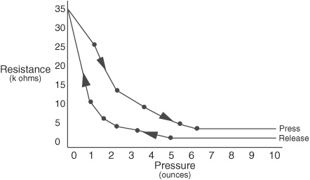
Figure 42-11 The readings from foam pad pressure sensors are not linear, and the values may be different depending on whether you are pressing down or releasing.
Now here’s the kicker: the transducer may not go back to 30 kΩ immediately when the object is released. It may spring up to 40 kΩ or go only as far as 25 kΩ. What’s important is that the software uses this new value as the new set point for the next occasion when the gripper grasps an object.
Connecting to a Microcontroller
Taking resistance readings is handy when you’re using a multimeter. Most microcontrollers (and computers, for that matter) don’t have an input that directly reads resistance. But many do have an analog input that converts a voltage to a digital value. From the digital value, your control program can do something useful with the information provided by the pressure transducer.
As detailed in Chapter 40, “Interfacing Hardware with Your Microcontroller or Computer,” you can readily convert resistance to voltage by adding a series resistor to the circuit. This creates a voltage divider. Figure 42-12 shows how to wire the pressure pad with a 10 kΩ series resistor.
In operation, a voltage will appear at the point where the transducer and resistor meet. Connect that to an analog-to-digital (ADC) microcontroller input, and you’re in business.
As all pieces of conductive foam are different, you’ll need to experiment with the value of the resistor. Start with the 10 kΩ value, and test for sensitivity. Adjust the value of the resistor up or down to improve the sensitivity, in order to make reading the pressure value easier. Try not to go much below 2.2 kΩ.
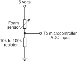
Figure 42-12 Electrical connection of a pressure pad to a microcontroller or other circuit that can read a voltage. You can increase or decrease the sensitivity of the pad by altering the value of the fixed resistor.
ON/OFF PRESSURE PAD
A variation on the theme is the on/off pressure pad. Rather than connect the conductive foam directly to an ADC input, you can route it to an analog comparator circuit—useful if your microcontroller doesn’t have an ADC or you don’t care about the exact pressure being exerted. The venerable LM339 IC contains four of these comparators in one very inexpensive package. Figure 42-13 shows a wiring diagram.
Experiment with the value of the dividing resistor connected to the foam. For the foam I used, I found good overall response with a 56 kΩ resistor, but you should feel free to try other values. What you want is a good voltage swing (foam pressed and not pressed) without many false readings. The 1-μF tantalum capacitor in parallel with the dividing resistor is optional. It smooths the voltage output of the foam.
In operation, the conductive foam and series resistor produce a voltage, which is fed into the noninverting input of the comparator. A 10 kΩ potentiometer is used to vary the reference voltage for the comparator. While applying fingertip pressure to the foam, set the potentiometer so that the output of the LM339 just goes from LOW to HIGH. Release the pressure, and the output should return to LOW again. In my experiments, I found that a reference voltage of 2.5 volts was just about right to register a modest push on the foam, with an almost immediate return to LOW when the pressure was released.
From time to time you may need to tweak the potentiometer, in order to set a new reference point. Conductive foam can age (dry out, go brittle), and its resistance can vary over days, months, or years.
FORCE-SENSITIVE RESISTORS
The homebuilt pressure sensors described so far leave a lot to be desired in terms of accuracy and repeatability. If you need greater accuracy, you should consider commercially available force-sensitive resistors, or FSRs. These cost more, but provide a more accurate resistance when a given pressure is exerted on them.
An FSR appears to a circuit like an ordinary resistor, so it can be used in the same kind of voltage divider circuits detailed previously. All the ways of interfacing a voltage divider to a circuit are available to you. See the previous section, and substitute the pressure pad with your force-sensitive resistor. Depending on the FSR, you may want to experiment with a higher or lower value for the bottom (fixed) resistor.
Force-sensitive resistors consist of a main pad that forms the sensing element. The pad comes in various shapes and sizes. For use as a robot fingertip, you can opt for a small, 5-to 10mm pad. For use as a robot bumper to detect collisions, you may want to go with a somewhat larger pad.
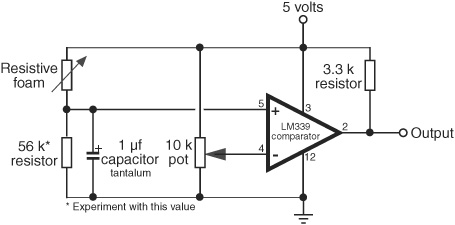
Figure 42-13 An LM339 voltage comparator IC can be used to construct an on/off switch using a pressure pad. Adjust the potentiometer for the threshold between on and off. This circuit works with any kind of resistive sensor.
You can also enlarge the contact area of the pad by using rubber balls cut in half. A 2″ round ball has a cross section of 2 inches, yet at the opposite pole it has a contact area of mere millimeters—perfect for a smallish FSR. Let your mind wander and you’ll think of plenty of clever homemade designs for enlarging the contact area of a force-sensitive resistor.
FLEX RESISTORS
A variation on the force-sensitive resistor is the flex resistor, similar to a resistive pad but greatly elongated (see Figure 42-14). This makes it more sensitive to the effects of bending. It’s ideal as a bumper detector on the front of your robot.
Example: Mount the flex resistor on a very thin piece of plastic (such as 1mm polystyrene from the hobby store), and mount this strip on the front of the bot so that it creates a flexible bow. Push in anywhere along the strip, and the value of the flex resistor changes.
As flex resistors are just variable resistors, use them in circuits like pressure-sensitive antistatic foam, previously discussed.
HOMEBREW SENSORS WITH CONDUCTIVE COATINGS
Conductive inks, paints, and adhesives may be used with rigid and flexible materials to make all manner of pressure, flex, and bend sensors. These coatings are impregnated with conductive materials (usually nickel, copper, or silver, or a combination of these). They may be combined with carbon-based rubber of the kind used in consumer remote control units or electrically conductive fabrics and threads.
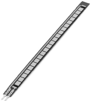
Figure 42-14 This resistive sensor detects when the plastic strip is flexed. Its resistance changes as the strip is twisted and deformed. Use the same kind of interface circuit as in Figure 42-12 to connect this to your microcontroller. (Photo courtesy SparkFun Electronics.)
An example conductive coating is CaiKote 44, a copper/silver which may be applied to glass, plastic, rubber, and many other materials. Use with conductive rubber bands to make stretch sensors (resistance changes as they stretch) or pieces of pressure-sensitive rubber sheet. See the RBB Online Support site (Appendix A for details) on how to find links to these and other conductive materials products.
Experimenting with Piezoelectric Touch Sensors
A new form of electricity was demonstrated more than a century ago when two scientists, Pierre and Jacques Curie, placed a weight on a certain crystal. The strain on the crystal produced an odd form of electricity—significant amounts of it, in fact. This new form of electricity was coined “piezoelectricity”; piezo is derived from the Greek word meaning “press.”
Later discoveries demonstrated that piezoelectric crystals undergo a physical transformation when voltage is applied to them. The piezoelectric phenomenon is a two-way street. Press the crystals and out comes a voltage; apply a voltage to the crystals and they respond by flexing and contracting.
HOW PIEZO MATERIALS PRODUCE VOLTAGE
All piezoelectric materials share a common molecular structure, in which all the movable electric dipoles (positive and negative ions) are oriented in one specific direction. Piezoelectricity occurs naturally in crystals that are highly symmetrical—things like quartz, Rochelle salt crystals, and tourmaline. The alignment of electric dipoles in a crystal structure is similar to the alignment of magnetic dipoles in a magnet.
When the piezoelectric material is placed under an electric current, the physical distance between the dipoles changes. This causes the material to contract in one dimension (or axis) and expand in the other. This is how piezoelectric buzzers work.
Conversely, placing the piezoelectric material under pressure (in a vise, for example) compresses the dipoles. This causes the material to release an electric charge.
While natural crystals were the first piezoelectric materials used, synthetic materials have been developed that greatly demonstrate the piezo effect. With these, even a small electric charge, applied through wires bonded to a piezoelectric element, causes the piezo material to vibrate at high frequencies.
Piezo activity is not confined to brittle ceramics like those used in piezo buzzers. It can also be made by pressing piezo material onto thin, clear sheets. These sheets are commonly referred to as PVDF piezo film—PVDF stands for polyvinylidene fluoride, a kind of plastic.
PVDF film is used in many commercial products, including noninductive guitar pickups, microphones, even solid-state fans for computers and other electrical equipment. For your robot, you can use premade PVDF elements as touch and force sensors, among other components.
EXPERIMENTING WITH PIEZO SENSORS
The ubiquitous ceramic piezo disc is perhaps the easiest form of piezoelectric transducer to experiment with. A sample disc is shown in Figure 42-15. The disc is made of nonferrous (no iron) metal. A ceramic-based piezo material is applied to one side. Most discs available for purchase are made for use as small speakers or buzzers. They have two leads already attached. The black lead is the “ground” of the disc and is usually directly attached to the metal rim.
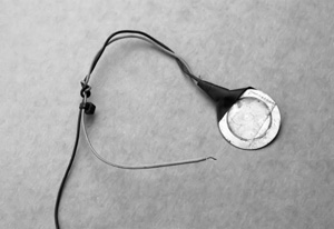
Figure 42-15 A homemade touch or “knock” sensor made with a piezoelectric disc, available as stand-alone components from many online electronics stores or in piezo speakers.
When the piezo material of the disc is under pressure—even a slight amount—the disc outputs a voltage proportional to the amount of pressure. This voltage is short-lived: shortly after the initial change in pressure, the voltage output of the disc will return to 0. A negative voltage is created when the pressure is released.
THINGS TO KEEP IN MIND
Whether you are experimenting with ceramic or flexible PVDF film, it’s important to understand a few basic concepts about piezoelectric materials:
![]() Piezoelectric materials are voltage sensitive. What this really means is that the more force you exert on a piezo element, the higher the voltage it will produce. That’s nice, as you can use it to determine relative force of impact. But it also means that you need to protect your electronic circuit by limiting the volts it gets from a piezo element.
Piezoelectric materials are voltage sensitive. What this really means is that the more force you exert on a piezo element, the higher the voltage it will produce. That’s nice, as you can use it to determine relative force of impact. But it also means that you need to protect your electronic circuit by limiting the volts it gets from a piezo element.
![]() Piezoelectric materials act as capacitors. This means they can develop and retain an electrical charge just by sitting there. Ordinarily, not good for a sensor. The easiest way to counter this is to “bleed” the voltage off using a resistor.
Piezoelectric materials act as capacitors. This means they can develop and retain an electrical charge just by sitting there. Ordinarily, not good for a sensor. The easiest way to counter this is to “bleed” the voltage off using a resistor.
![]() Piezoelectric materials are bipolar. Press down, and the material produces (for example) a positive voltage. Release, and the material produces a negative voltage. Remember that negative voltages can harm some kinds of electronic inputs.
Piezoelectric materials are bipolar. Press down, and the material produces (for example) a positive voltage. Release, and the material produces a negative voltage. Remember that negative voltages can harm some kinds of electronic inputs.
BUILDING AN INTERFACE CIRCUIT
A piezoelectric element is both a consumer and a producer of electricity. When the disc is connected to an input, any physical tap or pressure on the disc will produce a voltage. The exact voltage is proportional to the amount of force exerted on the disc: apply a little pressure or tap, and you get a little voltage. Apply a heavier pressure or tap, and you get a bigger voltage.
The piezoelectric material on ceramic piezo discs is so efficient that even a moderately strong force on the disc will produce in excess of 5 or 10 volts.

Figure 42-16 Protective interface circuit for use with piezo discs. The zener diode limits the voltage; the resistor limits the current. Your microcontroller or other circuit may already have input diodes, but this provides added protection.
![]() That’s good: it makes it easy to interface the discs to a circuit, since there is usually no need to amplify the signal.
That’s good: it makes it easy to interface the discs to a circuit, since there is usually no need to amplify the signal.
![]() But it’s also bad; the voltage and current from the disc could exceed the maximum inputs of the other electronic device you’re interfacing with. (In fact, pound on a piezo disc with a hammer, and, though it might be broken when you’re done, it will also produce a thousand volts or more.)
But it’s also bad; the voltage and current from the disc could exceed the maximum inputs of the other electronic device you’re interfacing with. (In fact, pound on a piezo disc with a hammer, and, though it might be broken when you’re done, it will also produce a thousand volts or more.)
Note the 5.1-volt zener diode shown in Figure 42-16. The diode, and the 330 Ω resistor are included to not only clamp the output of the disc to +5.1 volts (a safe level for most interface circuitry), but also limit the current produced by the disc.
In practice, most modern microcontrollers, including the Arduino, already have equivalent protection circuity built into them, so the zener and resistor may not be required. These components don’t alter the operation of the circuit, so add them if you’re not sure.
Recall that piezoelectric discs exhibit a capacitance. This means that over time the disc will take a charge, and the charge will show up as a constantly changing voltage at the output of the disc. To prevent this, be sure to insert a resistor across the output of the disc and ground. This resistor bleeds off the excess capacitance.
In my experiments with the specific discs I used, I found that a resistor of about 1 megohm eliminated the charge buildup without excessively diminishing the sensitivity of the disc.
![]() A higher value will increase sensitivity, but it could cause an extra charge buildup. You probably don’t want, or need, to exceed about 5.6 megohms.
A higher value will increase sensitivity, but it could cause an extra charge buildup. You probably don’t want, or need, to exceed about 5.6 megohms.
![]() A lower value will reduce the buildup but also reduce the sensitivity of the disc.
A lower value will reduce the buildup but also reduce the sensitivity of the disc.
Experimenting with Piezo Film
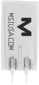
Piezo film, such as Kynar and other brands, is available in a variety of shapes and sizes. The wafers, which are about the same thickness as the paper in this book, have two connection points, as illustrated in Figure 42-17. Like ceramic piezo discs, these two connection points are used to activate the film with an electrical signal or to relay pressure on the film as an electrical impulse.
You can use piezo film to sense vibration, shock, touch, and pressure—everything you can do with a piezo disc you can do with the film.
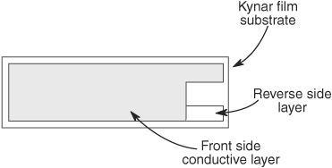
Figure 42-17 Piezo film is a special plastic material coated on either side with conductive material. The film comes in all shapes and sizes.
ATTACHING LEADS TO PIEZO FILM
Unlike piezoelectric ceramic discs, piezo film doesn’t always come with preattached leads. Soldering won’t work, as that’ll just melt the film plastic. For just a little bit more you can get sensors with leads already bonded to the film, and I highly recommend these. Otherwise, you can try one of the following alternative methods:
![]() Conductive ink, paint, or glue. Conductive ink, such as GC Electronics Nickel-Print paint, bonds thin wire leads directly to the contact points on piezo film. Apply a small globule of paint to the contact point, and then slide the end of the wire in place. Depending on drying time, you may need to wait several hours for the ink or glue to set up. Apply a strip of electrical tape to provide physical strength.
Conductive ink, paint, or glue. Conductive ink, such as GC Electronics Nickel-Print paint, bonds thin wire leads directly to the contact points on piezo film. Apply a small globule of paint to the contact point, and then slide the end of the wire in place. Depending on drying time, you may need to wait several hours for the ink or glue to set up. Apply a strip of electrical tape to provide physical strength.
![]() Self-adhesive copper-foil tape. You can use copper-foil tape designed for repairing printed circuit boards to attach wires to piezo film. The tape uses a conductive adhesive and can be applied quickly and simply. As with conductive inks and paints, apply a strip of electrical tape to the joint.
Self-adhesive copper-foil tape. You can use copper-foil tape designed for repairing printed circuit boards to attach wires to piezo film. The tape uses a conductive adhesive and can be applied quickly and simply. As with conductive inks and paints, apply a strip of electrical tape to the joint.
![]() Metal hardware. Use small 2-26 machine screws, washers, and nuts (available at hobby stores) to mechanically attach leads to the film. Poke a small hole in the film, slip the bolt through, add the washer, and wrap the end of a wire around the bolt. Tighten with the nut.
Metal hardware. Use small 2-26 machine screws, washers, and nuts (available at hobby stores) to mechanically attach leads to the film. Poke a small hole in the film, slip the bolt through, add the washer, and wrap the end of a wire around the bolt. Tighten with the nut.
USING PIEZO FILM AS A MECHANICAL TRANSDUCER
Figure 42-18 shows a simple circuit you can build that indicates when a piece of piezo film is struck or bent. Bending the film produces a voltage output, which is provided at the output. Connect this output to a microcontroller ADC (analog-to-digital converter) pin, an LM339 or similar-voltage comparator, or other circuit of your choosing. Note the extra components besides the piezo film:
![]() The small disc capacitor helps eliminate spurious signals. You can select a different value to better match the piezo film you’re connecting to. It really helps to have an oscilloscope to view the actual output of the circuit, but if you don’t, try different values to see what works best.
The small disc capacitor helps eliminate spurious signals. You can select a different value to better match the piezo film you’re connecting to. It really helps to have an oscilloscope to view the actual output of the circuit, but if you don’t, try different values to see what works best.
![]() The 1-megohm (or thereabouts) resistor prevents a charge from developing across the piezo film, causing an uneven voltage output. Experiment with this value—a higher value makes the circuit more sensitive, but also more prone to voltage fluctuations. A lower value does the reverse.
The 1-megohm (or thereabouts) resistor prevents a charge from developing across the piezo film, causing an uneven voltage output. Experiment with this value—a higher value makes the circuit more sensitive, but also more prone to voltage fluctuations. A lower value does the reverse.
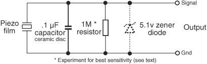
Figure 42-18 Simple circuit setup for experimenting with piezo film.

Figure 42-19 Prototype piezo film bend sensor. Two short pieces of piezo film are taped to a thin plastic sheet (a school report cover); the sheet acts as a backing and is formed into a half-circle to detect when the robot bumps into something.
![]() The 5.1 zener diode helps to prevent overvolting the circuit you’re connected to. It’s added as a precaution; many modern microcontrollers and other ICs already have this kind of diode protection on their inputs, and the zener may not be necessary. YMMV (your mileage may vary).
The 5.1 zener diode helps to prevent overvolting the circuit you’re connected to. It’s added as a precaution; many modern microcontrollers and other ICs already have this kind of diode protection on their inputs, and the zener may not be necessary. YMMV (your mileage may vary).
![]()
See the RBB Online Support site (refer to Appendix A) for hands-on examples of interfacing piezo discs and film to the Arduino and other microcontrollers. You’ll find commented programming code and alternative connection techniques.
CONSTRUCTING A PIEZO FILM BEND SENSOR
You can easily create a workable touch sensor by attaching one or two small piezo film transducers to a thick piece of plastic. The finished prototype sensor is depicted in Figure 42-19. The plastic membrane could be mounted on the front of a robot, to detect touch contact, or even in the palm of the robot’s hand. Any flexing of the membrane causes a voltage change at the output of one or both piezo film pieces.
For the plastic backing, I cut up one of those report covers available at office supply stores. And then I told the teacher my robot ate my homework.
A demonstration sketch for the Arduino is simple. This one displays (via the Serial Monitor window) a value from 0 to 1023, depending on how much flex there is in the bend sensor. In practice, and depending on the film you use, the value only goes from 0 to about 200, when using the standard 0-to-5-volt analog-to-digital converter reference (the Arduino lets you set a different reference, but this demo works fine for our purposes). In a working program, you might ignore any values under some minimal threshold (say, 5 or 10) and have your robot react to anything above that as a collision with some object.
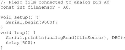
Remember that piezo film produces both positive- and negative-going signals. But the ADC on an Arduino only registers positive voltage change. Depending on how the film is oriented on the plastic, you may get a higher span of readings by reversing the connections of the film to the interface circuit in Figure 42-18.
On the Web: Build a Piezo Bumper Bar
Previous editions of Robot Builder’s Bonanza included full project plans for a “bumper bar” made with two piezo discs. The completed bumper bar is shown in Figure 42-20. In order to make room in this edition for new projects, I’ve moved the bumper bar to the RBB Online Support site; see Appendix A for information about the site. Plans for the bumper bar include construction, interfacing to microcontrollers, and sample code.
Also on the RBB Online Support site is a unique project that uses fiber-optic “whiskers” and the magic of laser light, plus other compliant (“soft-touch”) collision detection ideas you might like to try.
Other Types of “Touch” Sensors
The human body has many kinds of “touch receptors” embedded within the skin. Some receptors are sensitive to physical pressure, while others are sensitive to heat. You may wish to endow your robot with some additional touchlike sensors. You can find projects for many of these ideas in the remaining chapters of this book.
![]() Heat sensors can detect changes in the heat of objects within grasp.
Heat sensors can detect changes in the heat of objects within grasp.
![]() Air pressure sensors can be used to detect physical contact. The sensor is connected to a flexible tube or bladder (like a balloon); pressure on the tube causes air to push into or out of the sensor, thereby triggering it.
Air pressure sensors can be used to detect physical contact. The sensor is connected to a flexible tube or bladder (like a balloon); pressure on the tube causes air to push into or out of the sensor, thereby triggering it.
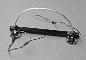
Figure 42-20 The completed piezo disc bumper bar. See full construction details on the RBB Online Support site.
![]() Microphones and other sound transducers make effective touch sensors. You can use microphones, either standard or ultrasonic, to detect sounds that occur when objects touch.
Microphones and other sound transducers make effective touch sensors. You can use microphones, either standard or ultrasonic, to detect sounds that occur when objects touch.
![]() Accelerometers measure shock and vibration. If your robot hits something, it will cause a shock or vibration that’ll be picked up by an accelerometer. Should it stop moving (the object is solid enough), the accelerometer will detect that as well.
Accelerometers measure shock and vibration. If your robot hits something, it will cause a shock or vibration that’ll be picked up by an accelerometer. Should it stop moving (the object is solid enough), the accelerometer will detect that as well.
![]() Touch fabric is fabric and threads that are electrically conductive. Originally designed for use in making garments, carpets, and other textiles resistant to static electricity buildup, you can use it in any robotic application where you need a flexible sensing area.
Touch fabric is fabric and threads that are electrically conductive. Originally designed for use in making garments, carpets, and other textiles resistant to static electricity buildup, you can use it in any robotic application where you need a flexible sensing area.