
Chapter 46
Making and Listening to Sound
The robots of science fiction are seldom mute or deaf. They may utter pithy sayings—“Don’t you call me a mindless philosopher, you overweight glob of grease!” Or squeak out blips and beeps in some “advanced” language only other robots can understand.
Voice and sound input and output make a robot more “human-like,” or at least more entertaining. What is a personal robot if not to entertain?
What’s good for robots in novels and in the movies is good enough for us, so this chapter presents a number of useful projects for giving your mechanical creations the ability to make and hear noise. The projects include using recorded sound, generating warning sirens, recognizing and responding to your voice commands, and listening for sound events. Admittedly, this chapter only scratches the surface of what’s possible today, especially with technologies like compressed digitized sound, and you’re encouraged to dive deeper into this interesting topic.
![]()
Source code for all software examples may be found at the RBB Online Support site. See Appendix A, “RBB Online Support,” for more details. To save page space, the lengthier programs are not printed here. The support site also offers source code with added comments, parts lists (with sources) for projects, updates, extended construction plans, and more examples you can try!
Preprogrammed Sound Modules
At the bottom of the sound food chain is the preprogrammed, or “canned,” sound module, typical in such products as greeting cards and musical ornaments. Most are programmed with a song, though a few—like the electronic whoopee cushion—are meant to emit a sound effect. Humor notwithstanding.
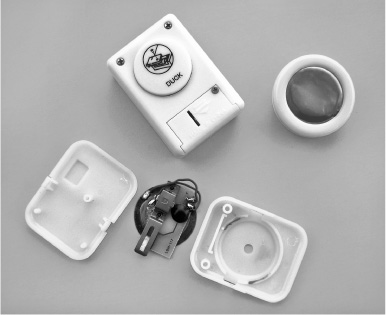
Figure 46-1 An assortment of sound modules with prerecorded sounds and songs on them. Most modules can be hacked to operate from electronic control.
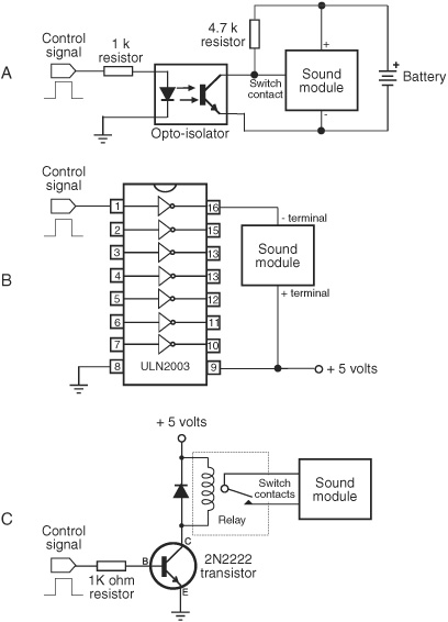
Figure 46-2 Some ways to connect a sound module to a microcontroller or other circuit for activation. Techniques include opto-isolator, power driver (turn battery supply on and off), and relay to replace the mechanical switch.
Most sound modules are completely self-contained, including a small speaker (piezo or dynamic magnet), a button battery, and some means to set it off, usually a small push-button switch. Several are shown in Figure 46-1. You can salvage the sound module from a greeting card or other product and reuse it in your robot. Craft stores are a good source of new sound modules that can be added to homemade ornaments.
Controlling a sound module from a microcontroller involves triggering the module by electrical signal, rather than by using its mechanical push button. Depending on the design of the module, you may be able to trigger it simply by replacing its push-button switch with the circuit shown in Figure 46-2A. An opto-isolator and accompanying parts bypass the switch. You trigger the module by momentarily bringing the microcontroller line that is connected to the opto-isolator to HIGH.
If the sound module is powered by more or less 5 volts, you can try hardwiring the trigger switch to on, and then control the module with operating juice from the micro controller line itself (Figure 46-2B). If your microcontroller doesn’t provide enough current to drive the module, try adding one of the buffers in a ULN2003 chip. The driver also acts as a buffer to help protect the microcontroller.
And finally, if the module operates at only 1.5 volts (a single button battery), you may need to use something like Figure 46-2C. Yank the mechanical switch from the module, and replace it with a small relay.
Commercial Electronic Sound Effects Kits
Among premade electronic kits, ones for sound effects are always popular. Several companies manufacture and sell sound effects kits that you can use as self-contained modules in your robot projects. For example, the light-sensitive Theremin Kit from Chaney Electronics produces distinctly outworldly sound effects by altering the amount of light falling on two sensors. The company also sells a 10-note sound kit and several others.
Most sound effects kits are designed to be self-contained. That means they come with an amplifier, if they need one, and a speaker. Controlling them on a robot requires interfacing the selector buttons to the outputs of your microcontroller, in much the same way as for the sound modules in the previous section. Most kits come with a schematic, and you can readily determine where to hook things up.

Using a driver IC, as previously described, to power and depower the board is among the best methods to turn the sound on and off, as it reduces overall current draw from the robot’s batteries when the sound effect isn’t needed. But there are other methods, such as using a CD4051 analog switch to control which sound-producing element is routed to the amplifier and speaker.
Making Sirens and Other Warning Sounds
If you use your robot as a security device or to detect intruders, fire, water, or whatever, then you probably want the machine to warn you of immediate or impending danger. The warbling siren shown in Figure 46-3 will do the trick, assuming it’s connected to a strong enough amplifier (some amp circuits are provided later in the chapter).
The circuit is constructed using two 555 timer chips; alternatively, you can combine the functions into the 556 dual-timer chip, but I prefer the separate chips because they provide a bit more room on the breadboard to experiment. The “warble speed” and pitch can be altered by changing the capacitors connected between pin 2 and ground of each chip.
![]() The timer on the left toggles HIGH and LOW about once a second. It makes the “warble.”
The timer on the left toggles HIGH and LOW about once a second. It makes the “warble.”
![]() The timer on the right produces the high-pitched siren sound and alternates between two frequencies. The two frequencies are controlled by the left timer, as it toggles HIGH and LOW.
The timer on the right produces the high-pitched siren sound and alternates between two frequencies. The two frequencies are controlled by the left timer, as it toggles HIGH and LOW.
When using an 8 or 16 Ω dynamic speaker, the sound output is pretty loud—enough for family members to come into your workshop and complain about it (yes, I speak from experience!). But if you need more oomph, connect the output of the second 555 to a high-powered amplifier. You can build an amplifier using an LM386 IC, as described later in the chapter, or get an audio amplifier kit with a wattage of 8, 16, or more. Start by looking at sellers of electronic kits in Appendix B, “Internet Parts Sources.”

Figure 46-3 Circuit diagram for a warbling siren, made using two LM555 timer ICs.
The circuit needs several small-value ceramic (monolithic or disc) capacitors to prevent the inevitable power supply glitches that are generated by the versatile but electrically “noisy” LM555 chips. I’ve specified 0.1 μF capacitor as a bypass capacitor connected to pin 5 of the “warbler.” More critical are the 0.01 μF capacitors as power supply decoupling, connected between the power pins (pins 8 and 1) of both chips. Try to get these decoupling capacitors as physically close to the IC as you can.
If you breadboard this circuit, keep the lead lengths to a minimum, especially for the capacitors. After you have tested the circuit, you will want to transfer it to a soldered breadboard and clip all the leads as short as possible.
Using a Microcontroller to Produce Sound and Music
Any microcontroller with a pulse width modulation (PWM) feature can be used to produce sound, and even music. When the PWM frequency is within the range of hearing—about 20 Hz to 20 kHz—we hear it as a tone. The sound is heard by passing the I/O line through a speaker or amplifier.
By varying the tones, you make sound. You can produce music with one PWM output (monophonic), or you can combine the outputs of two or more PWM I/O lines to create polyphonic sounds, like a music synthesizer. It’s easy to produce warning sirens, warblers, bio-sounds (a la R2-D2), and other effects.
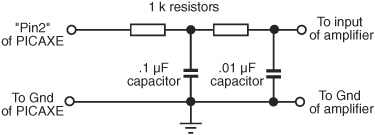
Figure 46-4 Recommended interface for bridging a PICAXE microcontroller with an amplifier circuit. You can use one of the amps detailed later in this chapter.
The PICAXE family of chips includes easy-to-use sound-making statements. Using the low-end PICAXE 08M, you can construct a programmable sound coprocessor for your robot, freeing your main microcontroller to handle the higher-level functions, such as motor control and sensors. The sounds are basic (don’t expect Hollywood movie effects) but more than enough for functional effects and feedback.
Figure 46-4 shows an example interface of a single-channel PWM sound output to an amplifier. For the amp you can use the LM368, detailed later in this chapter under “Using Audio Amplifiers.” The LM368 connects to a standard speaker with an 8 Ω or 16 Ω impedance.
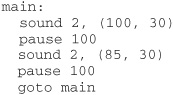
Use the PICAXE sound statement to produce a tone at a certain pitch for a certain duration. The syntax of the sound statement is straightforward:
![]()
![]() pin is the I/O pin number you’ve connected the amplifier to.
pin is the I/O pin number you’ve connected the amplifier to.
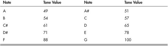
![]() tone is a numeric value of the pitch you wish to make. Valid values are from 0 to 255. See the table that follows for a quick reference of common tone values and the (approximate) musical scale notes they correspond to. (And note that you can pick in-between values for outworldly sounds.)
tone is a numeric value of the pitch you wish to make. Valid values are from 0 to 255. See the table that follows for a quick reference of common tone values and the (approximate) musical scale notes they correspond to. (And note that you can pick in-between values for outworldly sounds.)
![]() duration is the duration of the tone, with the value of 50 being approximately 1 second.
duration is the duration of the tone, with the value of 50 being approximately 1 second.
You can combine tones and duration in a single sound statement, to play successive notes:
![]()
plays C, D#, and E, with the first two notes lasting a half second, and the last note lasting a quarter second.
You can use loops of different kinds to produce sound effects. From the PICAXE manual, this short bit of code produces the high-low sound of a European police siren:
Experiment with other tone and duration values to see what kinds of effects you can come up with.
The sound statement uses pulse width modulation to produce noise. The PICAXE 08M and higher chips also have separate pwm and pwmout statements that provide additional functionality—namely, you can control the duration of the pulses, not just their frequency.
When using an op-amp and basic components like a resistor and capacitor, you can modify the shape of the pulses to alter the timbre of the sound; timbre is the tone quality of the sound. For example, by converting the shape of the pulses to a sawtooth, the sound is more like that of a violin (a rough approximation, of course). Sound design and engineering are beyond the scope of this book, but if you’re interested, visit the local library and look up analog music synthesizers.
Using Audio Amplifiers
Some of your sound-generating circuitry won’t need amplification, in which case you can merely connect a speaker directly. But others may need a little help. Figure 46-5 shows a rather straightforward 0.5-watt sound amplifier that uses the LM386 integrated amp. The sound output won’t shatter any windows, but the chip is easy to get, is cheap, and can be wired up quickly. It’s perfect for experimenting with sound projects.
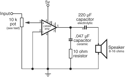
Figure 46-5 LM386 audio amplifier, wired for a gain of about 20.
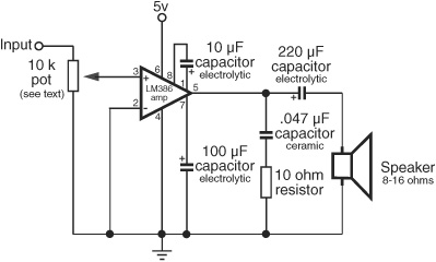
Figure 46-6 LM386 audio amplifier, wired for a gain of about 200.
The amplifier in Figure 46-5 has an amplification of approximately 20, and is perfectly suited to most robotic sound applications. By adding a few more components, the gain of the amp can be boosted 10 times, to 200 (see Figure 46-6). Either amplifier will drive a small 8- or 16-ohm speaker.
For best results, make sure the 10 kΩ potentiometer is the logarithmic (or audio) taper kind, not the typical linear taper. When using a linear taper pot, the sound volume will be affected at only one end of the dial. With a logarithmic potentiometer, the volume change will be more evenly spread across the dial.
Sound and Music Playback with a Microcontroller
My first robot used the mechanism from an old cassette recorder for its sound and music playback. It was, shall we say, clunky. Thanks to several ready-made add-on boards for the Arduino and other popular microcontrollers, you can incorporate melodies, effects, and other sounds where you have full control over what’s played—from short, quarter-second gunshots to 10-minute-long lullabies.
These add-ons use prerecorded sounds that you create on your computer. The sound files, which can be in WAV, MP3, WMA, OGG, or a proprietary format, are then transferred to a solid-state memory card, typically SD or μSD (micro SD, the tiny version of standard SD). The memory card is inserted into the playback board, which is controlled via simple commands from a microcontroller.
There are a number of breakout boards and shields for adding sound to the Arduino or other microcontroller. Most sound boards use solid-state memory cards to store sound, music, and effects files. The card is formatted in FAT16 (some support FAT32), meaning you can prepare the card on your computer and copy sound files to it.
The programming libraries to support reading the content of a memory card use up a lot of RAM in the microcontroller. For this reason, it’s always a good idea to use these projects with an MCU equipped with at least 2KB of RAM, and 32KB or more of flash memory. When using the Arduino, you want the version with the ATmega328 (or higher) controller chip.
Typically, sound files are stored as 8+3 DOS-style filenames on the memory card. Sound files can be any size, up to the capacity of the memory card, but as you can only place files into the root directory of the card, you are limited to 512 files total. That’s generally more than enough for any robotics application.
Some sound boards support the MP3 digital file standard. For example, the MP3 Trigger board from SparkFun (Figure 46-7) is a fully self-contained MP3 playback development module. It includes an onboard MP3 decoder chip (specifically, the VS1053), low-power amplifier (you can use an external amplifier if you need more volume), and a built-in μSD card reader.
The MP3 Trigger supports memory cards formatted with DOS FAT16, so you can prepare your music and other sound effects on your PC, then transfer the files to the μSD card for use with the board. Playback is controlled via a serial or direct triggered input, using 18 trigger pins.
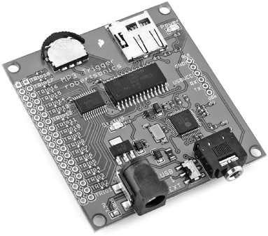
Figure 46-7 All-in-one MP3 playback board, which can be connected to a switch or a microcontroller for fully automated sound clip selection. It supports up to 256 sound clips, stored on a μSD card. You can use your PC to copy sound files to the card. (Photo courtesy SparkFun Electronics.)
Speech Synthesis: Getting Your Robot to Talk
Not long ago, integrated circuits for the reproduction of human-sounding speech were fairly common. Several companies mass-produced these chips for voice-driven products like the Speak-and-Spell toys. In most cases, these ICs could create unlimited speech because they reproduced the fundamental sounds of speech.
With the proliferation of digitized recorded voice, unlimited vocabulary speech synthesizers have become something of an exception. Using only software and a sound card, it is possible to reproduce a male or female voice. In fact, both Windows and Macintosh OS X come with free speech-making tools for their operating systems.
SPECIALTY SPEECH CHIPS
While most of the big chip makers have long exited the speech chip market, there are several low-cost solutions available to robot builders. These include:
![]() SpeakJet, from Magnevation
SpeakJet, from Magnevation
![]() Soundgin, from Savage Innovations
Soundgin, from Savage Innovations
Both create human voice effects using allophones, which are discrete sounds made by the mouth and vocal cords during speech. The allophones are essentially strung together to create what sounds like someone talking. Though not as clear as a real human voice, the staccato nature of the sound in fact adds to the effect. Your robot actually sounds like it’s talking, rather than using prerecorded sound from somewhere.
Both the SpeakJet and Soundgin are also complex sound generators, including “biologic” sound effects, TouchTone phone tones, and alarm sounds. The chips contain independent oscillators that can re-create the human vocal tract and sound effects, and, in the case of the Soundgin, can synthesize music.
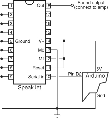
Figure 46-8 Basic connection for connecting a SpeakJet sound-processing IC to an Arduino. Serial data of the voice or sound to play is sent via pin D2 on the Arduino.
Simple serial communication connects either speech chip to a microcontroller. The Speak-Jet can also be commanded to play any of 16 preset phrases through its eight event inputs, which can be directly connected to bumper switches on the robot.
Figure 46-8 shows a minimal circuit for connecting the SpeakJet. I’ve left out the audio output components, amplifier, and speaker, as these are well documented in the SpeakJet datasheet. The following speakjet.pde program for the Arduino microcontroller contains a simple phrase that says, “I am a robot.” The allophone codes to use for the phrase were obtained with the Phrase-A-Lator program, available from the Magnevation Web site.
When wiring things together, make sure that the ground connections of the SpeakJet, PICAXE, and audio amplifier (if you use one) are all tied together, and that everything operates from the same 5 volt source.

speakjet.pde

If your hookup doesn’t produce any sound, try putting the SpeakJet into demo mode by connecting pin 13 of the SpeakJet (labeled M0) to 5V instead of to Gnd. The SpeakJet should announce “Ready” and then go through a routine of sound effects. Go back to regular mode by reconnecting pin 13 to 5V.
Be very careful to not place pin 12 of the SpeakJet to Gnd when in demo, or you may put the chip into Baud Configure mode. In this mode the SpeakJet will try to match whatever serial baud rate it detects on its serial input pin (pin 10). The baud rate is stored inside the chip and remains until reconfigured.
If you now get weird random sounds when trying to send the SpeakJet a speech phrase, a likely cause is that the baud rate of the chip is no longer the default 9600 baud and therefore doesn’t match the serial data being sent to it by the Arduino.
Refer to the SpeakJet documentation for the details on reconfiguring the baud rate, but here it is in a nutshell: connect pin 13 to 5V, and pin 12 to Gnd. You’ll know you’re in Baud Configure mode when you hear a series of “sonar pings.”
Replace the char phrase line in the speakjet.pde sketch with the following code:
![]()
Compile and download the sketch. Let the program run 10 to 15 seconds, then unplug power to the SpeakJet. Rewire pins 13 and 12 to those shown in Figure 46-8, and re-download the original speakjet.pde sketch to the Arduino. Now, hopefully, the SpeakJet’s baud rate will be set back to the proper 9600 baud.
Having to type in codes instead of text can be a real hassle. An alternative is the TTS256 Text to Code IC for SpeakJet and Soundgin, available from www.speechchips.com. This IC accepts words as text, and it in turn creates the allophone sounds for use with the speech synthesizer chips.
It won’t pronounce every word correctly (in fact, the designer of the chip guarantees that it won’t!), but for those tough-to-decode words, you can enter allophone sounds directly.
Listening for Sound
Next to sight, the most important human sense is hearing. And compared to sight, sound detection is far easier to implement in robots. Simple “ears” you can build in less than an hour let your robot listen to the world around it.
Sound detection allows your robot creation to respond to your commands, whether they take the form of a series of tones, an ultrasonic whistle, or a hand clap. It can also listen for the telltale sounds of intruders or search out the sounds in the room to look for and follow its master. Once detected, the sound can trigger a motor to motivate, a light to go lit, a buzzer to buzz, or a computer to compute.
MICROPHONE
Obviously, your robot needs a microphone (also called a mic or mike) to pick up the sounds around it. The most sensitive type of microphone is the electret condenser, which is used in most higher-quality hi-fi mikes. The trouble with electret condenser elements, unlike crystal element mikes, is that they need electricity to operate. Supplying electricity to the microphone element really isn’t a problem, however, because the voltage level is low—under 4 or 5 volts.
Most all electret condenser microphone elements come with a built-in field-effect transistor (FET) amplifier stage. As a result, the sound is amplified before it is passed on to the main amplifier. Electret condenser elements are available from a number of sources, including RadioShack, for under $3 or $4. You should buy the best one you can. A cheap microphone isn’t sensitive enough.
The placement of the microphone is important. You should mount the mike element at a location on the robot where vibration from motors is minimal. Otherwise, the robot will do nothing but listen to itself. Depending on the application, such as listening for intruders, you might never be able to place the microphone far enough away from sound sources or make your robot quiet enough. You’ll have to program the machine to stop, then listen.
MICROPHONE AMPLIFIER
Use the circuit in Figure 46-9 as an amplifier for the microphone. The circuit is designed around an op-amp; the op-amp used is an OPA344, which you may not be familiar with. Unlike the ubiquitous LM741 op-amp, the OPA344 is intended to run using a single-ended power supply—that is, you don’t need to provide both + and − power. It’s also known as a rail-to-rail amp, meaning its output varies from 0 volts to the full supply voltage (or pretty close to it).
Sometimes it’s just easier to work with circuits that are ready-made as modules or boards. I especially feel that way about sound amplifier circuits, which tend to work best when they’re constructed on printed circuit boards—stray capacitance and all that jazz. Fortunately, circuit boards and modules for amplifying sound are common and relatively inexpensive, sometimes cheaper than if you buy all the parts separately.
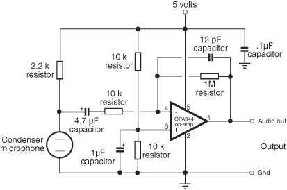
Figure 46-9 Microphone preamplifier circuit. You can build the amp yourself or get it ready-made. (Circuit courtesy SparkFun Electronics.)
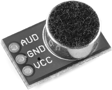
Figure 46-10 Electret condenser microphone and components for a preamplifier mounted on a breakout board. Supply power (see text), and connect the AUD terminal to a circuit or microcontroller to monitor sound. (Photo courtesy SparkFun Electronics.)
The little module in Figure 46-10 is a good example: it’s the microphone, op-amp, and other parts shown in Figure 46-9, available as a teeny-tiny breakout board (model BOB-09964), ready for immediate use in your project. It comes preassembled, which is good because it uses small surface-mount parts that fly across the room when you sneeze. Just hook up the power (2.7 to 5.5 volts), and connect the AUD amplified audio output to the rest of your circuit.
CONNECTING TO YOUR MICROCONTROLLER
With the sound detector hardware finished, you can connect the electronics to a microcontroller. Figure 46-11 shows an interface that will conform the output signal from the amplifier to a level that is easier to use with a microcontroller analog-to-digital input. The capacitor is included to remove the steady DC voltage present at the amplifier output. The diode makes the output signal positive-going only.
When connecting to an Arduino, you may have better luck using an external power supply, rather than powering the microcontroller via the USB port. If this isn’t practical, try powering the microphone module from the 3.3V pin of the Arduino pin, or else using a separate regulated 5-volt supply for the amp.
After downloading the sketch, open the Serial Monitor window to see the actual values registered through the amplifer. Assuming the module is powered by 5 volts, theortically the values will vary from 0 to 1023, representing the full 0- to 5-volt voltage swing of the amplifier output.
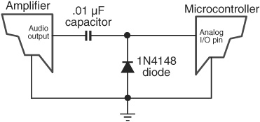
Figure 46-11 How to connect the microphone amplifier to a microcontroller. Be sure the ground connections are shared. See text for power source recommendations.
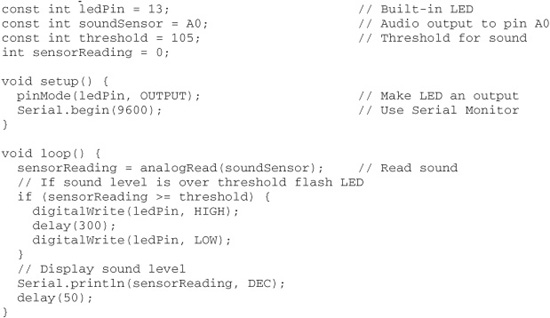
Note the threshold value set at the top of the sketch. Sounds over this level cause the Arduino’s built-in LED to light up. Even with no sound in the room, the amp will deliver some voltage to its output—and more than you might think because of thermal noise, which is the “hiss” you hear when turn up an amplifier. Depending on your wiring, you should expect an ambient (quiet room) level of between 0 and 25, especially if you experiment near your PC with its cooling fan. Therefore, set the threshold to some value above the ambient level, so that louder sounds trigger the LED.
sounddetect.pde
Sound metering is a science in its own right, and the preceding example is a simplistic way to monitor audio levels. One method that you might like to research includes adding a peak detector circuit, useful for catching those fleeting high-output sounds that might otherwise get missed. The peak detector stores the highest volume detected in that period. After checking the volume level, the circuit is cleared.
Peak detector circuits can be constructed using op-amps and a small assortment of standard parts (resistors, capacitors, diodes, and maybe a transistor). Research on the Web to see what you come up with!
On the Web: More Sound Projects
Check out the RBB Online Support site (see Appendix A) for more ideas and projects for using sound with your robots.
![]() How to use an LM339 voltage comparator to set the “trip point” of the sound level you want to capture. Because the output of the comparator is a digital LOW/HIGH signal, you don’t have to use an ADC input on your microcontroller.
How to use an LM339 voltage comparator to set the “trip point” of the sound level you want to capture. Because the output of the comparator is a digital LOW/HIGH signal, you don’t have to use an ADC input on your microcontroller.
![]() How to literally “stretch out” the fleeting signal from the comparator so that your microcontroller is sure to catch it.
How to literally “stretch out” the fleeting signal from the comparator so that your microcontroller is sure to catch it.
![]() How to hack inexpensive recording sound modules; put your own voice into your robot.
How to hack inexpensive recording sound modules; put your own voice into your robot.
![]() How to route multiple sound sources to one amplified output.
How to route multiple sound sources to one amplified output.
![]() How to produce sound on a PC-based robot.
How to produce sound on a PC-based robot.
![]() How to use PC-based sound generation software to create synthesized speech, music, and robotic voice and special effects.
How to use PC-based sound generation software to create synthesized speech, music, and robotic voice and special effects.
![]() How to implement speech recognition in your robot.
How to implement speech recognition in your robot.