
Chapter 39
Using the BASIC Stamp
Since its inception, the Parallax BASIC Stamp has provided the onboard brains for countless robot projects. This thumbprint-sized microcontroller uses BASIC-language commands for instructions and is popular among robot enthusiasts, electronics and computer science instructors, and even design engineers looking for an inexpensive alternative to microprocessor-based systems. The original BASIC Stamp has been greatly enhanced, and new models sport faster speeds, more memory capacity, easier software programming, and additional data lines for interfacing with motors, switches, and other robot parts.
In this chapter, you’ll learn the fundamentals of the BASIC Stamp and how to use it in your robot building. You will also want to read Chapters 37 and 38, which provide full coverage of the very popular Arduino and PICAXE microcontrollers. Like the BASIC Stamp, the PICAXE also has BASIC embedded in it, while the Arduino uses a variation of the C programming language.

This chapter concentrates on the BASIC Stamp 2. There are other versions of the BASIC Stamp, including the older BASIC Stamp 1, BS-SX, and others. Features and functionality vary by model. Be sure to check the Parallax Web site at www.parallax.com for more information.
Inside the BASIC Stamp
The BASIC Stamp starts life as an off-the-shelf PIC from Microchip Technologies. “PIC” stands for “programmable integrated circuit,” though other definitions are also commonly cited, including “peripheral interface controller” and “programmable interface controller.” Embedded in this PIC is a proprietary BASIC-like language interpreter called PBasic.
FROM PC TO BASIC STAMP
The chip stores commands downloaded from a PC or other development environment. When you run the program, the language interpreter built inside the Stamp converts the instructions into code the chip can use. Common instructions involve such things as assigning a given data line as an input or output or toggling an output line from high to low in typical computer-control fashion.
The net result is that the BASIC Stamp acts like a programmable electronic circuit, with the added benefit of intelligent control—but without the complexity and circuitry overhead of a dedicated microprocessor. Instead of building a logic circuit out of numerous inverters, AND gates, flip-flops, and other hardware, you can use just the BASIC Stamp module to provide the same functionality and do everything in software. (To be truthful, the Stamp often requires that at least some external components interface with real-world devices.) Nor do you need to construct a microprocessor-based board for your robot followed by the contortions of programming the thing in some arcane machine language.
Because the Stamp accepts input from the outside world, you can write programs that interact with that input. For instance, it’s a slam dunk to activate an output line—say, one connected to a motor—when some other input (like a switch) changes logic states. You could use this scheme, for instance, to program your robot to reverse its motors if a bumper switch is activated. Since this is done under program control and not as hardwired circuitry, it’s easier to change and enhance your robot as you experiment with it.
STAMP MEMORY
The microcontroller of the BASIC Stamp uses two kinds of memory: PROM (programmable read-only memory) and RAM. The PROM memory is used to store the PBasic interpreter; the RAM is used to store data while a PBasic program is running. Memory for the programs that you download from your computer is housed in a separate chip (but is still part of the BASIC Stamp itself; see the description of the BS2 module in the next section). This memory is EEPROM, for “electrically erasable programmable read-only memory” (the “read-only” part is a misnomer, since it can be written to as well).
In operation, your PBasic program is written on a PC, then downloaded—via a serial connection—to the BASIC Stamp, where it is stored in EEPROM. The program in the EEPROM is in the form of “tokens”; special instructions that are read, one at a time, by the PBasic interpreter stored in the BASIC Stamp’s PROM memory. During program execution, temporary data are kept in RAM. Note that the EEPROM memory of the BASIC Stamp is nonvolatile—remove the power, and its contents remain. The same is not true of the RAM. Remove the power from the BASIC Stamp, and any data stored in the RAM are gone. Also note that the PBasic interpreter, which is stored in the PROM memory of the microcontroller, is not replaceable.
As a modern microcontroller, the BASIC Stamp 2 is a little tight when it comes to available memory space. The chip sports only 2K of EEPROM and just 32 bytes of RAM. Of those 32 bytes, 6 are reserved for storing the settings information of the input/output pins of the BASIC Stamp, leaving only 26 bytes for data. For many robotics applications, the 2K EEPROM (program storage) and 26-byte RAM (for data storage) are sufficient. However, for complex designs, you may need to use a second BASIC Stamp or select a microcontroller—such as the BASIC Stamp 2-SX or the Parallax Propeller—that provides more memory.
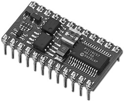
Figure 39-1 The BASIC Stamp 2 is a self-contained microcontroller, complete with the controller chip itself, plus voltage regulator and other parts. It comes on a small circuit board that has the same size as a 24-pin-wide integrated circuit. (Photo Courtesy Parallax Inc.)
Stamp Alone or Developer’s Kit
The BASIC Stamp is available directly from its manufacturer or from a variety of dealers the world over. The prices from most sources are about the same. In addition to the BS1, BS2, and BS2-SX variations mentioned earlier, you’ll find that the BASIC Stamp is available in several different premade kits as well as a stand-alone product.
![]() BS2 Module. The BASIC Stamp module (see Figure 39-1) contains the actual microcontroller chip as well as other support circuitry. All are mounted on a small printed circuit board that is the same general shape as a 24-pin IC. In fact, the BS2 is designed to plug into a 24-pin IC socket. The BS2 module contains the microcontroller that holds the PBasic interpreter, a 5-volt regulator, a resonator (required for the microcontroller), and a serial EEPROM chip.
BS2 Module. The BASIC Stamp module (see Figure 39-1) contains the actual microcontroller chip as well as other support circuitry. All are mounted on a small printed circuit board that is the same general shape as a 24-pin IC. In fact, the BS2 is designed to plug into a 24-pin IC socket. The BS2 module contains the microcontroller that holds the PBasic interpreter, a 5-volt regulator, a resonator (required for the microcontroller), and a serial EEPROM chip.
![]() BASIC Stamp Board of Education. Typically sold without a BS2 module, the Board of Education, known also as BOE, offers you a convenient way to experiment with the controller. It contains connectors for four R/C servo motors, and a mini-size solderless breadboard. The BOE provides connectors for quick hookup to a PC to program the Stamp chip. It’s available in serial and USB versions.
BASIC Stamp Board of Education. Typically sold without a BS2 module, the Board of Education, known also as BOE, offers you a convenient way to experiment with the controller. It contains connectors for four R/C servo motors, and a mini-size solderless breadboard. The BOE provides connectors for quick hookup to a PC to program the Stamp chip. It’s available in serial and USB versions.
![]() BS2 Discovery Kit. The discovery kit is ideal for those just starting out. It includes a BS2 module, a Board of Education board, a programming cable, a power adapter, software on CD-ROM, and an assortment of electronics components used in a series of tutorial lessons.
BS2 Discovery Kit. The discovery kit is ideal for those just starting out. It includes a BS2 module, a Board of Education board, a programming cable, a power adapter, software on CD-ROM, and an assortment of electronics components used in a series of tutorial lessons.
![]() Boe-Bot. The Boe-Bot is a small metal-fabricated mobile robot kit built around the BS2 chip and includes the BASIC Stamp Board of Education. If you already have a BS2 and BOE, you can purchase just the Bot chassis, which comes with motors, wheels, and all hardware.
Boe-Bot. The Boe-Bot is a small metal-fabricated mobile robot kit built around the BS2 chip and includes the BASIC Stamp Board of Education. If you already have a BS2 and BOE, you can purchase just the Bot chassis, which comes with motors, wheels, and all hardware.
Physical Layout of the BS2
The BASIC Stamp 2 is a 24-pin device; 16 of the pins are input/output (I/O) lines that you can use to connect with your robot. For example, you can use I/O pins to operate a radio-controlled (R/C) servo. Or you can use a stepper motor or a regular DC motor, when you use them with the appropriate power interface circuitry. As outputs, each pin can:
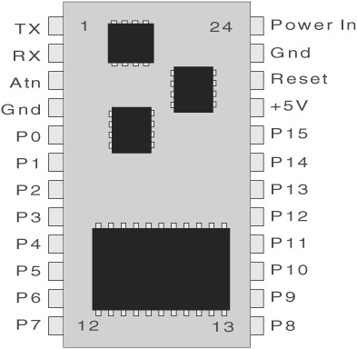
Figure 39-2 Pinout diagram of the BS2 chip. As usual, pin numbering starts at the upper left and goes counterclockwise.
![]() Source 20 mA of current (that is, supply current to the load).
Source 20 mA of current (that is, supply current to the load).
![]() Sink about 25 mA.
Sink about 25 mA.
However, the entire BS2 should not source or sink more than about 80 to 100 mA for all pins in combination. You can readily operate a series of LEDs, without needing external buffer circuitry to increase the power-handling capability.
Or you can connect the BS2 to an ultrasonic ranging module (see Chapter 43, “Proximity and Distance Sensing”), various bumper switches, and other sensors. The direction of each I/O pin can be individually set—some pins can be used for outputs and others for inputs. You can dynamically configure the direction of I/O pins during program execution. This allows you to use one pin as both an input and an output.
Figure 39-2 shows the pin layout of the BS2. In addition to power and communications pins, the BS2 offers 16 I/O lines, customarily identified as P0 through P15 (sometimes the P is omitted). Through PBasic commands, you can control all 8 bits of the port together or each pin individually.
Hooking Up: Connecting the BASIC Stamp to a PC
The BASIC Stamp was engineered to make it easy to connect to a personal computer, using only a serial port or a USB port. These days many computers don’t have a serial port; they use USB instead. If your computer lacks a serial port, you’re best off getting a USB-to-serial adapter, or opt for a BASIC Stamp experimenter’s board that already has a USB connector on it. You shouldn’t rely on power provided by the USB connection to operate your BASIC Stamp. Provide the BASIC Stamp with its own power source. If using the BASIC Stamp by itself, you can connect a 9-volt battery to its power terminals; the built-in voltage regulator will provide the proper volts for the chip.
Once connected to the PC (USB or serial), you need only install the software from the CD or downloaded from the Parallax site, and you’re set to go.
Understanding and Using PBasic
As you’ve read earlier in this chapter, at the heart of the BASIC Stamp is PBasic, which is the language used to program the BASIC Stamp. PBasic has undergone many changes during the life of the BASIC Stamp products, and the syntax and the commands are different between PBasic for the BASIC Stamp 1 (known as PBasic1) and PBasic for the BS2 (PBasic 2.0 and 2.5).
Unless otherwise noted, what follows is PBasic 2.0 for the BASIC Stamp 2. Though there is a later version of the language, 2.0 programs still work in all current BS2 chips. Examples of programming code in PBasic 2.0 are more common on the Web; as this book doesn’t live in a vacuum, I decided to stick with version 2.0–style code, to avoid causing unnecessary confusion.
Version 2.5 adds some additional (and worthwhile) software statements to make your programs more streamlined, and these are noted separately later on in the chapter. You’re free to adopt whatever version you wish, and mix and match them. Just be sure that, if you wish to use PBasic 2.5 features, you have the correct version of the software from the Parallax Web site.
PBasic programs for the BASIC Stamp are developed in the BASIC Stamp Editor, an application that comes with the Starter Kit—it’s also available for free download at the Parallax Web site. The Editor lets you write, edit, save, and open BASIC Stamp programs. It also allows you to compile and download your finished programs to a BASIC Stamp. The download step requires that your BASIC Stamp be connected to a carrier board or other circuit board attached to a download cable. The download cable is connected to your PC via a serial or USB serial port. Figure 39-3 shows the BASIC Stamp Editor.
Like any language, PBasic is composed of a series of statements that are strung together in a logical syntax. A statement forms an instruction that the BS2 is to carry out. For example, one statement may tell the chip to fetch a value on one of its I/O pins, while another may tell it to wait a certain period of time. The majority of PBasic statements can be categorized into three broadly defined groups: variable and pin or port definitions, flow control, and special function. We’ll cover each of these next.
VARIABLE AND PIN/PORT DEFINITIONS
As with any programming language, PBasic uses variables to store bits and pieces of information during program execution. Variables can be of several different sizes; you should always strive to choose the smallest variable size that will accommodate the data you wish to store. In this way you will conserve precious RAM space (remember, you have only 26 bytes of RAM to work with!).
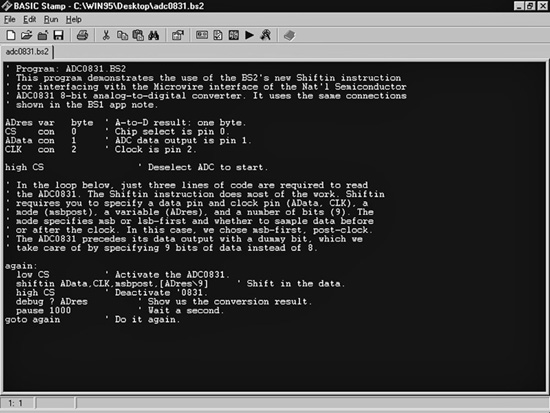
Figure 39-3 The BASIC Stamp 2 integrated programming environment, which runs on your personal computer. Here, you write your programs and download them to the BS2 chip via a serial or USB connection.
PBasic provides the following four variable types:
![]() Bit—1 bit (one-eighth of a byte)
Bit—1 bit (one-eighth of a byte)
![]() Nibble—4 bits (4 bits)
Nibble—4 bits (4 bits)
![]() Byte—1 byte (8 bits)
Byte—1 byte (8 bits)
![]() Word—2 bytes (16 bits)
Word—2 bytes (16 bits)
Variables must be declared in a PBasic program before they can be used. This is done using the var statement, like so:
![]()
where VarName is the name (or symbol) of the variable, and VarType is one of the variable types just listed. Here’s an example:
![]()
Red is a bit, and Blue is a byte. Note that capitalization does not matter in a PBasic program.
Once declared, variables can be used throughout a program. The most rudimentary use for variables is with the = (equals) assignment operator, as in
   Red = 1

   Blue = 12
Variables can also be assigned as the result of a math expression (2 + 2) or as the value of an input pin. For example, suppose an input pin is connected to a mechanical switch. Ordinarily, the switch is open, and the value at the pin is LOW (0). Suppose a variable, called Switch, stores the current value of the pin. The Switch variable would contain 0 as long as the switch is opened. If the switch is closed, the Switch variable then stores 1 (or logical HIGH). More about I/O pins in a bit.
Variables store values that are expected to change as the program runs. PBasic also supports constants, which are used as a convenience for you. Constants are declared much as variables are, using the con statement:
MyConstant con 5
MyConstant is the name of the constant, and its value is 5.
The BASIC Stamp treats its 16 I/O pins like additional memory. The instantaneous value of an I/O pin functions exactly like a 1-bit variable: the value is either 0 or 1. If the I/O pin is an input, then the value of that input will be 0 or 1, depending on the condition of the circuit on the outside of the BASIC Stamp. The mechanical switch is a good example of this: depending on whether the switch is opened or closed, the value of the input pin is 0 (open) or 1 (closed).
When I/O pins are used as outputs, their logical state is changed using the high, low, and toggle statements. In each case, the number of the pin (0 through 15) is given to tell the BASIC Stamp which I/O you want to change:
![]() High brings the I/O pin HIGH (1).
High brings the I/O pin HIGH (1).
![]() Low brings the I/O pin LOW (0).
Low brings the I/O pin LOW (0).
![]() Toggle changes the state of the I/O pin from 0 to 1, or vice versa, depending on its previous value.
Toggle changes the state of the I/O pin from 0 to 1, or vice versa, depending on its previous value.
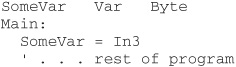
Here’s an example (using the traditional apostrophe character for inline comments):
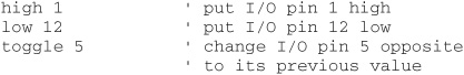
As with nearly all microcontrollers, I/O pins are distinct from the physical pins on the chip. When it says low 12, this means the pin labeled P12 in the BASIC Stamp documentation and on carrier boards such as the Board of Education. It is not physical pin #12, which is actually I/O pin 7 (P7).
There are many ways to determine the current value of an I/O pin that is used as an input. Most are used with special functions, which are outlined later in this chapter. You can also directly reference the value of an input by using the Inx statement, where x is a number from 0 to 15. For instance, to read the value of pin 3 and put it into a variable, you’d use the following:
FLOW CONTROL
Flow control statements tell your program what to do next. A commonly used flow control statement is if, which is used in conditional expressions that execute one part of the program if condition A exists and another part of the program if condition B exists. Two other flow control statements are goto and gosub, which are used to unilaterally jump from one part of a program, and the for statement, which is used to repeat a block of code a specific number of times. Let’s look first at the if statement.
Using the if Statement
The if statement, which is always used in conjunction with the then statement, conditionally branches execution depending on the outcome of an expression. The syntax is as follows:
if Expression then Label
Expression is the condition that must resolve to a True or False statement, and Label is an identified label elsewhere in the program that the execution is to jump to. An example of a typical Expression is checking the value of a variable or input pin against an expected value:
if MyVar=1 then Flash
If the content of MyVar is equal to 1 (the expression is True), then the program is expected to jump to the Flash label. This label is identified by the label name, followed by a colon, as in:
   Flash:

   … rest of the code goes here
The if expression can use a number of logical operators:
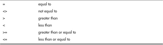
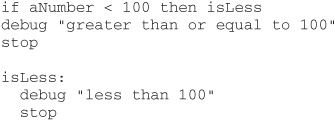
For PBasic 2.0, the if statement is a little funky compared to other modern programming languages, in that the result of the expression branches execution to a label. Note that there is no explicit else or endif keyword in PBasic 2.0, that is, an action to be taken if the expression is False. As cited in the BASIC Stamp manual, you must write if statements that have a True and False component along these lines:
FYI
If you prefer the if … else … endif structure, you can use the enhanced flow control statements found in PBasic 2.5 and described more fully later in this chapter.
Notice how this bit of programming works: should aNumber be less than 100, then the program jumps to the isLess label, and the debug statement (which prints text in the debug window of the BASIC Stamp programming environment on your PC) prints “less than 100.” However, if aNumber is 100 or higher, the jump to isLess is ignored, and the program simply executes the next line, which is yet another debug statement (“greater than or equal to 100”). Note the introduction of another flow control statement: stop. The stop statement stops program execution.
Using the goto and gosub Statements
The goto and gosub statements are used with labels to divert execution to another part of the program. Goto is most often used to create endless loops, as shown here:
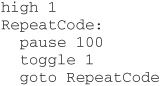
In this program, I/O pin 1 is set to 1 (HIGH). The program then pauses for 100 milliseconds (one-tenth of a second) and then toggles I/O pin 1 to its opposite state. The goto statement makes the program jump back to the RepeatCode label. With each trip through the code, I/O pin 1 is toggled HIGH or LOW. If the pin is connected to an LED, for example, it would flash on and off rapidly 10 times each second.
Gosub is similar to goto, except that when the code at the label is done, the program returns to the statement immediately after gosub. Here’s an example:
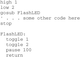
The program begins by setting I/O pin 1 to HIGH and I/O pin 2 to LOW. It then “calls” the FlashLED routine, using the gosub statement. The code in the FlashLED routine toggles I/O pins 1 and 2 from their previous state, waits one-tenth of a second (100 milliseconds), and then returns with the return flow control statement. Note the stop statement used before the FlashLED label. It prevents the code from reexecuting the FlashLED routine when it is not intended.
Using the for Statement
The for statement is used with the to and next statements. All form a controlled counter that is used to repeat the code a set number of times. The syntax for the for statement is:
for Variable = StartValue to EndValue [more statements] next
Variable is a variable that is used to contain the current count of the for loop. StartValue is the initial value applied to Variable. Conversely, EndValue marks the maximum value that will be applied to Variable. The loop breaks out—and the rest of the program continues to execute—when the Variable exceeds EndValue. For example, if you use the following,
for VarName = 1 to 10
the loop starts with 1 in VarName and counts to 10. The for loop is repeated 10 times. You don’t have to start with 1, and you can use an optional step keyword to tell the for loop that you want to count by 2s, 3s, or some other value:
![]()
For loops are used to execute whatever programming lies between the for and next statements. Here’s a simple example:
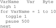
This program repeats the for loop a total of 10 times. At each iteration through the loop, I/O pin 1 is toggled (HIGH to LOW, and back again).
The BASIC Stamp supports additional flow control statements, all of which are detailed in the BASIC Stamp manual. These include Branch and End.
SPECIAL FUNCTIONS
The PBasic language supports several dozen special functions that are used to control some activity of the chip, including ones to sound tones through an I/O pin or to wait for a change of state on an input. I’ll briefly review here the special functions most useful for robotics. You’ll want to study these statements more fully in the BASIC Stamp manual (available for free download from Parallax and also included in the Starter Kit as a printed book).
![]() button. The button statement momentarily checks the value of an input and then branches to another part of the program if the button is in a LOW (0) or HIGH (1) state.
button. The button statement momentarily checks the value of an input and then branches to another part of the program if the button is in a LOW (0) or HIGH (1) state.
![]() debug. The BASIC Stamp Editor has a built-in terminal that displays the result of bytes sent from the BASIC Stamp back to the PC. The debug statement “echoes” numbers or text to the screen and is highly useful during testing.
debug. The BASIC Stamp Editor has a built-in terminal that displays the result of bytes sent from the BASIC Stamp back to the PC. The debug statement “echoes” numbers or text to the screen and is highly useful during testing.
![]() freqout. The freqout statement is used to generate tones primarily intended for audio reproduction. You can set the I/O pin, duration, and frequency (in Hertz) using the freqout statement.
freqout. The freqout statement is used to generate tones primarily intended for audio reproduction. You can set the I/O pin, duration, and frequency (in Hertz) using the freqout statement.
![]() input. The input statement makes the specified I/O pin an input. As an input, the value of the pin can be read in the program.
input. The input statement makes the specified I/O pin an input. As an input, the value of the pin can be read in the program.
![]() pause. The pause statement is used to delay execution by a set amount of time. To use pause, you specify the number of milliseconds (thousandths of a second) to wait.
pause. The pause statement is used to delay execution by a set amount of time. To use pause, you specify the number of milliseconds (thousandths of a second) to wait.
![]() pulsin. The pulsin statement measures the width of a single pulse with a resolution of 2 microseconds (2 μs). Pulsin is handy for measuring time delays in circuits, such as the return “ping” of an ultrasonic sonar.
pulsin. The pulsin statement measures the width of a single pulse with a resolution of 2 microseconds (2 μs). Pulsin is handy for measuring time delays in circuits, such as the return “ping” of an ultrasonic sonar.
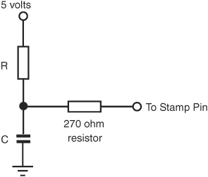
Figure 39-4 Basic RC (resistor-capacitor) setup for testing a voltage at an input pin, using a resistor and a capacitor. The BASIC Stamp manual provides more information on selecting the value of the resistor and capacitor.
![]() pulsout. Pulsout is the inverse of pulsin: with pulsout you can create a finely measured pulse with a duration of between 2 μs and 131 milliseconds (ms).
pulsout. Pulsout is the inverse of pulsin: with pulsout you can create a finely measured pulse with a duration of between 2 μs and 131 milliseconds (ms).
![]() rctime. The rctime statement measures the time it takes for an RC (resistor/capacitor) network to discharge to an opposite logical state. The rctime statement is often used as a simplified analog-to-digital circuit. Figure 39-4 shows a sample circuit.
rctime. The rctime statement measures the time it takes for an RC (resistor/capacitor) network to discharge to an opposite logical state. The rctime statement is often used as a simplified analog-to-digital circuit. Figure 39-4 shows a sample circuit.
![]() serin and serout. Serin and serout are used to send and receive asynchronous serial communications. Both commands require that you set the particulars of the serial communications, such as data (baud) rate, and the number of data bits for each received word. One application of serout is to interface a liquid-crystal display (LCD) to the BASIC Stamp.
serin and serout. Serin and serout are used to send and receive asynchronous serial communications. Both commands require that you set the particulars of the serial communications, such as data (baud) rate, and the number of data bits for each received word. One application of serout is to interface a liquid-crystal display (LCD) to the BASIC Stamp.
![]() shiftin and shiftout. The serin and serout statements are used in one-wire asynchronous serial communications. The shiftin and shiftout statements are used in two- or three-wire synchronous serial communications. The main difference is that with shiftin/shiftout a separate pin is used for clocking the data between its source and destination.
shiftin and shiftout. The serin and serout statements are used in one-wire asynchronous serial communications. The shiftin and shiftout statements are used in two- or three-wire synchronous serial communications. The main difference is that with shiftin/shiftout a separate pin is used for clocking the data between its source and destination.
Interfacing Switches and Other Digital Inputs
You can easily connect switches, either for control or for “bump” or other contact sensors, to the BASIC Stamp using either of the approaches shown in Figure 39-5. The simplest way to detect a switch closure is with the Inx statement (x is a number from 0 to 15 that denotes a pin). For example:
if In3 = 1 then
checks if input pin 3 is 1 (HIGH).
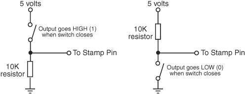
Figure 39-5 When using switch inputs, use a 10 kΩ resistor connected to ground or 5 volts, depending on whether you want the input pin to be LOW or HIGH when the switch is open.
You can also use the button statement, described briefly earlier in the chapter, to determine the current value of the switch. The button statement also includes a built-in debounce feature, so the BASIC Stamp will ignore the typical “noise” that occurs when a mechanical switch closes. Consult the BASIC Stamp manual for how to use button. It’s not very intuitive, but it gets the job done.
Interfacing DC Motors to the BASIC Stamp
The BASIC Stamp is ideal for controlling a DC motor that is connected to an H-bridge circuit (see Chapter 22, “Using DC Motors”). In the typical H-bridge for a single motor, the BASIC Stamp controls the on/off operation of the motor using one pin and the direction using another pin. By using the high and low statements, you can control the motor easily, turning it on and off and reversing its direction.
The BASIC Stamp code for controlling a DC motor is relatively straightforward: use the high or low statements and indicate which I/O pins you wish to use. For example, suppose your motor H-bridge is connected to pins 0 and 1, with pin 0 used for on/off control and pin 1 used for direction. Note that when pin 0 is low (0), the motor is off and therefore the setting of pin 1 doesn’t matter.

Here is an example:

By using labeled routines and the gosub statement, you can define common actions and develop more compact programs:

Interfacing RC Servo Motors to the BASIC Stamp
Servo motors for radio-controlled (R/C) cars and airplanes can be easily connected to and controlled with a BASIC Stamp. In fact, the code required for operating a servo motor is very simple.
You may connect any I/O pin of the BASIC Stamp directly to the signal input of the servo (see Chapter 23, “Using Servo Motors,” for more information on servo motors, how they work, and their electronic connections). Keep in mind that the BASIC Stamp cannot provide operating power to the servo motor; you must use a separate battery or power supply for it.
Figure 39-6 shows a good approach for connecting a common RC servo to the BASIC Stamp by using a separate battery supply for the servo. Note that the ground connections of the power supplies for both the BASIC Stamp and the servo are connected. If electrical noise poses a problem for you, you can try adding a 1 μF tantalum capacitor. between the +V and ground connections for the BASIC Stamp.
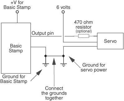
Figure 39-6 Basic connection for attaching a BS2 chip to an RC servo.
To operate the servo, use the pulsout statement, which sends a pulse of a specific duration to an I/O pin. Servos need to be “refreshed” with a pulse about 50 times each second to maintain their position. By adding a delay (using the pause statement) and a loop, your BASIC Stamp can move and maintain any position of the servo. The following examples show the basic program, using pin 0 as the control signal line to the servo. It sets the servo in its approximate center position:

Here’s how the program works: pin 0 is set as an output and set to low, with the low 0 statement. The repeating loop is defined as the code between the Loop: label and the goto Loop statement. The pulsout statement sends a 1500-microsecond pulse (LOW-HIGH-LOW) to pin 0. The value of 750 is used because pulsout has a minimum resolution of 2 μs; 750 times 2 is 1500 μs. A pulse of 1500 μs will position the output shaft of the servo in its approximate center position.
The pause statement pauses execution for 20 milliseconds (ms). When the loop is run, it will repeat about 50 times each second (20 ms * 50 = 1000 ms, or 1 second). Note that you can insert additional pulsout statements if you need to control other servos. The BASIC Stamp can adequately control seven or eight servos, but in doing so, it won’t have much processing time left over for anything else.
To change the angular position of the servo motor, merely alter the timing of the pulsout statement:
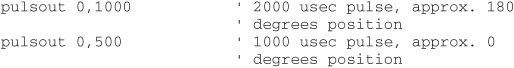
These values assume a strict 1000- to 2000-μs operating range for a full 0 to 180° rotation. This is actually not typical. You will likely find that your servo will have a full 180° rotation with higher and lower values than the nominal 1000 to 2000 μs. You can determine this only through experimentation. See Chapter 23, “Using Servo Motors,” for more details on this topic.
Additions in PBasic 2.5
With the introduction of PBasic 2.5 you can apply more structure to your programs, making them easier to write, fix, and read months after you’ve written them. Here are several of the more prominent changes made in PBasic 2.5.
IF-ELSE-ENDIF STRUCTURE
Rather than write if statements using goto’s and gosub’s, which can create so-called spaghetti code (that is, it goes all over the place and the strands are hard to track), in PBasic 2.5 you can define module if-else-endif structures to keep everything contained in one spot. For example, the code
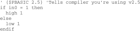
looks at I/O pin 0, and if HIGH (1), I/O pin 1 is switched HIGH; otherwise, it’s switched LOW.
SELECT-CASE-ENDSELECT
Sometimes you want to test a value against a variety of conditions. The value of I/O pins will always be either one of two states, 0 or 1, but the value of a byte-wide variable, or four I/O pins reading a 4-bit value, needs something more. You can construct convoluted if statements to test for all of the variations (16 for a nibble; 256 for a byte), but the easier approach is to use the select-case-endselect structure.
An example:
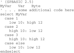
MyVar is assigned as a Byte variable. Somewhere along the line in the program the value of MyVar is set to some value. The example code looks for three explicit values, 1, 2, and 3. Depending on the value, I/O pins 10 and 12 are set LOW or HIGH, in some combination.
Note the case else. This is the “catch-all,” what happens if some other value (if any) matches what’s in MyVar. Here, for any value other than 1, 2, or 3, I/O pins 10 and 12 are both set LOW.
DO/WHILE/UNTIL-LOOP
Structured loops allow your program to continue until some condition is met—or not met. Statements within the loop structure are repeated. PBasic 2.5 supports three variations of conditional loops:
![]() do-loop repeats commands infinitely. There is no actual condition here; the do-loop is engineered to repeat code over and over again, as is common in the main loop of a robot control program.
do-loop repeats commands infinitely. There is no actual condition here; the do-loop is engineered to repeat code over and over again, as is common in the main loop of a robot control program.
![]() do-while-loop repeats commands until a condition is false. The “do while” is evaluated like an if statement.
do-while-loop repeats commands until a condition is false. The “do while” is evaluated like an if statement.
![]() do-until-loop repeats commands until a condition is true.
do-until-loop repeats commands until a condition is true.
do-loop Example

The statements between do and loop repeat over and over again. As noted, you’d typically use this for your main program code.
do-while loop Example
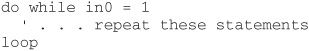
The statements between do while and loop are repeated as long as I/O input 0 is 1 (HIGH).
do-until loop Example
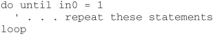
The example shows how do-while and do-until are the inverse of one another. The statements between do until and loop are repeated as long as I/O input 0 is not 1 (HIGH).
Exiting do-loops Early
From time to time you may wish to exit a do-loop before the conditions (in the case of while and until) are met. This can be accomplished with the exit statement, which is usually a part of some if expression or other structure. For example:

Here the do-while loop continues as long as I/O input 1 is 0 (LOW). However, another test can break out of the loop: if I/O input 0 is 1 (HIGH), the loop is also broken.