
Chapter 47
Interacting with Your Creation
Robots are like children—occasionally they just like talking back. Using any of several feedback techniques, your robot can communicate back to you, so you know that your programming is working the way it should. Several easy-to-implement feedback techniques are covered in this chapter.
There’s another aspect of robot-to-human interaction, bridging that psychological gap between machine and person. You can draw in human spectators by using movement, sound, lights, and color. Previous chapters dealt with providing movement and sound; in these pages you’ll learn some simple techniques to add pizzazz and flair (15 pieces or otherwise) to your robot. The more personal your bot is, the more others will take an interest in it.
![]()
Source code for all software examples may be found at the RBB Online Support site. See Appendix A, “RBB Online Support,” for more details. To save page space, the lengthier programs are not printed here. The support site also offers source code with added comments, parts lists (with sources) for projects, updates, extended construction plans, and more examples you can try!
Using LEDs and LED Displays for Feedback
One light-emitting diode is all it takes for your robot to communicate with you. The language may not be elegant, and the conversations are strikingly short, but it gets the job done. When you don’t need a talkative bot, you can use a single LED, or, for more words in the language, use multiple LEDs or 7-segment LED display panels.
FEEDBACK WITH ONE LED
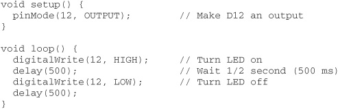
The basic LED feedback circuit is shown in Figure 47-1: it’s one of the I/O pins of your robot’s microcontroller connected to a current-limiting resistor and an LED. Code running in your controller, like the supersimple program shown in led.pde (for an Arduino), turns the LED off and on. Vary the delay value to make the LED flash on and off at a faster or slower rate.

Figure 47-1 Basic connection for illuminating an LED via a microcontroller pin. Bringing the pin HIGH turns the LED on.

led.pde
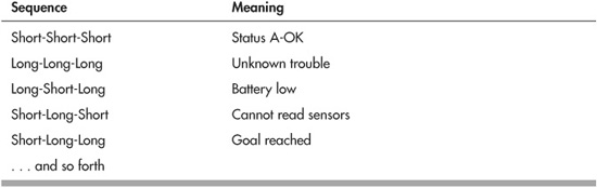
Remember that you’re not limited to lighting an LED merely to show status—either good or bad. You can flash the LED, using various patterns, to communicate more variations. Use Morse code to relay a variety of conditions or to “speak” phrases.
If you don’t know Morse code, you can invent your own system. Here are just a few ideas. Note that in each case, there’s an Off pause between the three-flash sequence.

Put the LED where it’s easy to see, and select a component large and bright enough to make it visible from across the room. I like to use large, 5mm bright red or yellow LEDs, mounted on the top of the robot, that can be seen at any angle.
FEEDBACK WITH MULTIPLE LEDS
Use multiple light-emitting diodes when you want to quickly convey operating or sensor status. For example, you might light an LED each time one of the bump switches or proximity detectors senses an object.
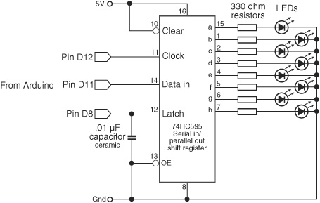
Figure 47-2 A 74595 serial-in, parallel-out (SIPO) shift register converts just a few microcontroller I/O lines to eight outputs.
When only a small number of LEDs are needed, you can wire them directly to the I/O pins of your microcontroller. You simply duplicate the circuit and code in the preceding section, “Feedback with One LED,” and use a different output pin for each light-emitting diode.
If you want to use more than four or five LEDs, then you probably don’t want to dedicate an I/O pin for each one. With a simple serial-in, parallel-out (SIPO) shift register, you can turn three pins into eight.
Refer to Figure 47-2 for a schematic using a 74595 SIPO integrated circuit. This chip is widely available and inexpensive. You can select any member of the ’595 family, such as the 74HC595 or 74HCT595, whatever is available to you.
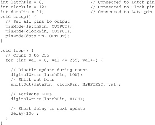
Sample program code for the Arduino is shown in multi_led.pde. The shift register works by first setting the Latch line to LOW and keeping it there for the time being. Then 8 bits of data are sent, bit by bit, to the Data pin of the chip. For each bit, the Clock pin on the ’595 is toggled to tell the chip that new data have been sent.
The Arduino makes sending serial data easy because it packages up the Data and Clock activities in one simple statement, shiftOut. To use this statement you specify the number of the Data pin and Clock pin, the order of the data to be sent, and the value—from 0 to 255—that you wish to use.
shiftOut(dataPin, clockPin, MSBFIRST, numberValue);
MSBFIRST tells the Arduino that you wish to send the data starting with the most significant bit, which is the most common. For example, to send the value 127, the Arduino first converts it to binary form, which is 10000000. It then sends the bits left to right, starting with the 1.
The other variation, LSBFIRST, sends the least significant bit first, or right to left. Some circuits you interface to may require this order.
After all the shifted-out data have been sent, the program returns the Latch pin to HIGH. This sets the output pins of the 74595 chip, illuminating the LEDs as desired.
multi_led.pde
FEEDBACK WITH 7-SEGMENT LED DISPLAYS
Your robot can also talk to you using a 7-segment numerical LED display. You can light up the segments to produce numerals, in which case your robot can output up to 10 “codes” to indicate its status. For instance, 0 might be okay, 1 might be battery low, and so on.
You can also illuminate the segments to make nonnumeric shapes. You can light up each segment individually or in combination. Figure 47-3 shows some variations, including an E for Error, H for help, and numerous symbols that can mean special things.
Displaying Numerals
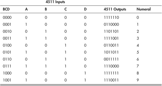
The easiest way to show numerals on a 7-segment display is to use a display driver IC, such as the CD4511 or 7447. These chips have four inputs and eight outputs—seven outputs for the numeric segments and an eighth for the decimal point, which we won’t be using in this example. To display a number, set its binary-coded decimal (BCD) value at the A-D input lines.

Figure 47-3 Unusual nonnumeric shapes can be created by activating selected segments of a 7-segment LED display. Use this system to display numbers (of course) or codes.
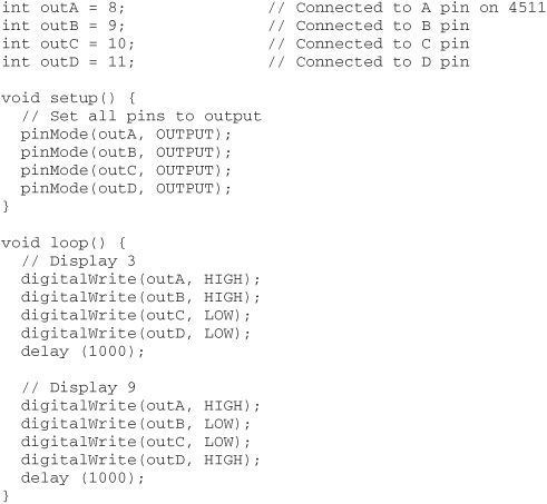
Refer to Figure 47-4 for a diagram for hooking up the CD4511 to a common-cathode 7-segment LED display. See segment.pde for a simple Arduino sketch that sends different values to the CD4511, lighting up different segments. (You can use the same general concept with individual LEDs.)
The circuit shows a common-cathode 7-segment LED module; that is, all the LED segments in the display share the same cathode connection. Be sure yours is also a common-cathode display and not a common-anode display.
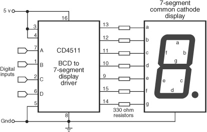
Figure 47-4 Connection diagram for a CD4511 BCD (binary-coded decimal) to a 7-segment driver. Numbers appear in the display based on the binary-coded values on the A to D input pins.
segment.pde
Displaying Arbitrary Shapes
Seven-segment displays are really just multiple LEDs that share a common cathode (or anode) connection. You can light up the segments separately, as in the section “Feedback with Multiple LEDs,” earlier in the chapter.
Refer to Figure 47-5 for how you can connect a 74595 SIPO chip to a 7-segment display. Use the program segment_shapes.pde to send out 8 bits to light the seven segments, plus decimal point. With this setup, you’re still able to produce all 10 digits, of course, plus Predator-type alien language symbols that only you (and your robot) understand.
segment_shapes.pde
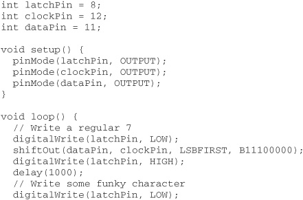
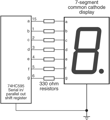
Figure 47-5 The 74595 SIPO (serial-in, parallel-out) shift register driving a 7-segment LED display. Using the shift register allows any combination of segments to light.
   shiftOut(dataPin, clockPin, LSBFIRST, B01110011);

   digitalWrite(latchPin, HIGH);

   delay(1000);

  }
You might find it easier to issue numbers in binary format, least significant bit first, as shown in the example. The first bit is segment A (see Figure 47-4), the second is segment B, and so forth. Here’s a handy binary bits guide for producing standard numerals via the 74595 shift register. Even if you don’t use the decimal point, be sure to include its bit at the end, or the display won’t look right.

Feedback via Simple Sounds
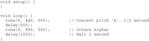
Tones through a small speaker can provide auditory feedback. Connection is simple—you might not even need an amplifier—and so is the programming. You need a microcontroller that can produce pulse width modulated signals. Most can, using built-in commands. For this example I’ll use the Arduino, which has sound-producing commands built in.
If you’ve used IBM or compatible PCs for any length of time, you’ll recognize that this concept is just like the power-on self-test (“POST”) diagnostics built into these computers. On power-up, but before the operating system was loaded, the PC would emit a series of short tones through its built-in speaker; the sequence of the tones indicated status.
See Figure 47-6 for a hookup diagram showing the Arduino connected to a piezo speaker. You can also connect the Arduino to a small amplifier to boost the sound; see Chapter 46, “Making and Listening to Sound.” The sketch in tones.pde shows how to produce a couple of simple beeps for the purpose of communicating status. The number and meaning of the tones are completely up to you.
In tones.pde, the tone statement plays a note through a specified pin—in this case, digital pin D8, which is connected to the piezo speaker. The second parameter is the frequency in hertz (cycles per second). A frequency of 440 Hz is “concert pitch A” or “concert A.” This is the A above middle C on a piano. A frequency of 880 Hz is also an A, exactly one octave higher.
The third parameter of the tone statement is the duration. The program plays both 440 Hz and 880 Hz A’s for half a second, before waiting 1 second, and repeating. Over and over and over again, and over …
tones.pde
Using LCD Panels
Liquid-crystal display (LCD) panels let your robot talk to you in complete words, even sentences. Even the smallest of LCD panels can show up to eight characters—enough for a couple of words. If needed, your robot can display a verbose error code that indicates its state.
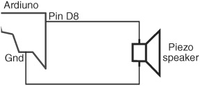
Figure 47-6 Basic connection diagram for driving a piezo speaker from an Arduino microcontroller pin. Sound is produced using the Arduino tone programming statement.
LCDs are particularly handy in testing and debugging when your robot is untethered from its programming computer. You can keep the LCD updated with the current program flow, indicating such things as when a sensor is activated and what program subroutine the robot’s microcontroller is currently running.
TEXT- OR GRAPHICS-BASED
LCD panels are broadly available in two general forms: text and graphics. The differences are obvious, but let’s discuss the two in brief:
![]() Text-based LCDs produce only text and other characters (such as dollar signs or symbols) stored inside the display module. The capacity of display is defined as the number of characters per line and the number of lines. For example, a 16×1 LCD has one line that can display up to 16 characters. A 32×2 LCD has two lines, and each line can display up to 32 characters.
Text-based LCDs produce only text and other characters (such as dollar signs or symbols) stored inside the display module. The capacity of display is defined as the number of characters per line and the number of lines. For example, a 16×1 LCD has one line that can display up to 16 characters. A 32×2 LCD has two lines, and each line can display up to 32 characters.
![]() Graphics-based LCDs (GLCDs) are more like computer monitors, where text and other images are produced using a horizontal and vertical array of dots. The graphics LCD, or GLCD, is defined by the number of dots wide and high; 256×128 means the display panel has 256 pixels horizontally and 128 dots vertically.
Graphics-based LCDs (GLCDs) are more like computer monitors, where text and other images are produced using a horizontal and vertical array of dots. The graphics LCD, or GLCD, is defined by the number of dots wide and high; 256×128 means the display panel has 256 pixels horizontally and 128 dots vertically.
Some GLCDs come with (or have as an option) a touch screen overlay, allowing you to press directly on the display to provide feedback. Most touch screens are resistive, meaning you can (and probably should) point on them using a rubber stylus.
Many text and graphics panels share standardized interface controllers, making it much easier to work with them. The controller is the electronics built into the LCD that provide the communications gateway.
For text displays, the most common controller is the Hitachi HD44780. For GLCD displays, the de facto standard controller is the Samsung KS0108. Other manufacturers make controllers that are compatible with these standards.
COLOR, MONOCHROME, BACKLIGHTING
Both text and graphics LCD products are available in either monochrome or color versions. Color is more common with GLCD, and color adds to the cost and the complexity in programming. Unless you specifically need it, stick with monochrome displays. (Note that the actual display color can be yellow on green, white on black, or numerous other variations.)
Many of the better LCD panels have their own backlighting, which increases the contrast under many types of indoor and outdoor light conditions. Though backlighting is not strictly required, it’s a nice feature to have.
LCD INTERFACE TYPES
Before you can use an LCD panel, you must interface it to a microcontroller. There are two ways, parallel and serial:
![]() Parallel interfacing involves connecting separate I/O pins from the microcontroller to the LCD. Text-based LCDs require seven I/O lines; GLCDs require about 16 I/O lines, which obviously makes these harder to interface. Your program communicates directly with the controller onboard the LCD panel.
Parallel interfacing involves connecting separate I/O pins from the microcontroller to the LCD. Text-based LCDs require seven I/O lines; GLCDs require about 16 I/O lines, which obviously makes these harder to interface. Your program communicates directly with the controller onboard the LCD panel.
![]() Serial interfacing involves connecting two or three I/O lines from the microcontroller to the LCD. Your program communicates with the LCD via serial commands. Additional electronics on the LCD convert these commands to the parallel interface used on the panel.
Serial interfacing involves connecting two or three I/O lines from the microcontroller to the LCD. Your program communicates with the LCD via serial commands. Additional electronics on the LCD convert these commands to the parallel interface used on the panel.
As text-based LCDs are by far the most common (and many controllers have built-in functions to support them), I’ll concentrate just on these. The example that follows shows how to connect an Arduino microcontroller to an HD44780-based text LCD. To keep it simple, the example uses a 16×2 LCD, which is common and inexpensive.
There are few established standards for the command set used with serial LCDs, so if you’re planning on using a serial LCD, refer to the instruction manual that came with it. It’ll tell you how to connect the panel to your controller, how to set up communications (such as setting the baud rate), and how to send commands to the LCD.
Figure 47-7 shows the hookup diagram between the Arduino microcontroller and an HD44780-based 4-bit parallel-character LCD module. It also shows how to use a 10 kΩ potentiometer for adjusting the contrast of the display. Dial the pot for the clearest lettering against the display background.
Remember: Your LCD display needs to be compatible with the Hitachi HD44780 driver. Most are, but you’ll want to check to make sure. The pinout order shown in Figure 47-7 is the most common you’ll encounter, but variations exist in oddball LCD panels. Your panel may have 14 pins (no LED backlight) or 15 or 16 pins (with LED backlight).
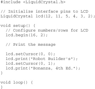
Program lcd16x2.pde provides a basic programming example that displays “Robot Builder’s Bonanza. 4th Ed.” on the two lines of the display.

Figure 47-7 Pinout diagram for a standard 4-/8-bit parallel LCD character panel (the LCD must use the Hitachi HD44780 driver). The LCD is used in 4-bit mode to save I/O pins.
lcd16x2.pde
Once again, the 10 kΩ potentiometer adjusts the contrast of the display. For a quick setup, you can try simply tying pin 3 (Vo) of the LCD to Gnd. Or connect it to pin D9 of the Arduino, and add this line at the start of the setup() function:
![]()
This uses the PWM feature of the Arduino to set a very low voltage to pin 3 of the LCD. Play around with different values for the second parameter of the analogWrite statement, from 0 to 255. On many LCD panels, the higher the number, the less contrast there is.
Robot-Human Interaction with Lighting Effects
Few onlookers will ever ask you, “What does it do,” if your robot makes funny sounds or blinks lots of lights. Robot interaction includes making it interesting to humans. The more engaging the robot becomes, the more interaction it engenders. That increases the impact the robot has on its human watchers.
There are plenty of ways to attract attention to your robot, such as using musical tones and sound effects, and even making your bot stop every once in a while and do a little booty shake.
I’ll let you figure out the booty shake part (hint: it has something to do with starting and stopping the drive motors), but for music and other auditory effects, be sure to read Chapter 46, “Making and Listening to Sound.”
The premier method of adding light effects to your bot is with light-emitting diodes. LEDs have gone well beyond small, dim, red pinpoints of light. They’re now available in all colors of the rainbow. Brightness has been drastically improved to the point where LEDs are used as flashlights.
FYI
Read more about LED basics in Chapter 31, “Common Electronic Components for Robotics.” Included is how to select the current-limiting resistor used to prevent the LED from burning up.
MULTIPLE LEDs
Don’t be content to use just one LED. Use multiple LEDs, of the same or a different color, mounted at various places on your robot. From a calculation standpoint, it’s easiest to connect each LED to the robot power supply through its own current-limiting resistor. This also helps ensure an even brightness from each of the LEDs. As long as you stay under the maximum forward current specification of the LED, you can vary the value of the current-limiting resistor to change the brightness of each LED.
SUPERBRIGHT AND ULTRABRIGHT LEDs
The typical LED produces a fairly low amount of light—a few millicandles (a candle is a standard unit of light measurement; a millicandle is 1/1000 of a candle). Superbright and ultra-bright LEDs produce 500 to 5000 millicandles; some go even higher. A few are so bright that they can cause eye damage if you stare into their beam.
Superbright and ultrabright LEDs are particularly striking on small robots. Turn down the lights and let your bot roam the floor. If you have a camera with an open-shutter (also called open-bulb) feature, you can take a long-exposure picture that shows the path of the robot around the room.
When selecting superbright and ultrabright LEDs, pay particular attention to beam pattern. The brightest LEDs have a narrow beam pattern—just 10 or 15 degrees. Select a broader beam pattern if you want the LED to be visible at different viewing angles.
Many very bright LEDs require more current than can be provided by the output pins of some microcontrollers. You’ll need to boost the current to the LED using a transistor (Figure 47-8) or a current driver (Figure 47-9). The driver shown is the ULN2003 Darlington transistor array, where each of its seven drivers can provide up to 500 mA (half an amp) of current, depending on the version of the chip. If you need eight drivers, you can use the ULN2803. It’s functionally identical to the ULN2003, except for the extra driver. Of course, the chip has more pins.
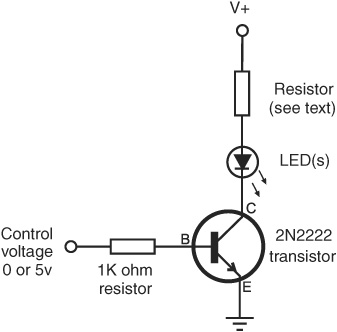
Figure 47-8 Superbright and similar high-output LEDs may require more drive current than a microcontroller I/O pin can supply. The transistor boosts the current driving the LED. Select the resistor to maintain a safe current through the LED.
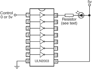
Figure 47-9 A buffer or driver may also be used to drive (one or more) LEDs. The ULN2003 chip contains seven high-output drivers, each capable of supplying several hundred milliamps of current.
Again, remember: LEDs need a current-limiting resistor, or else they’ll quickly burn out. Refer to Chapter 31 for the formula. In order to calculate the value of the resistor, you need to know the forward voltage through the LED, as well as the maximum current that can be safely passed through the device. Refer to the datasheet that came with the LED you’re using.
MULTICOLOR LEDs
Some LEDs are engineered to produce more than one color. Chapter 31, “Common Electronic Components for Robotics,” covered this topic, but here it is again in a nutshell. There are several kinds of multicolor LEDs:
![]() Bicolor LEDs contain red and green LED elements (other color combinations are possible, too). You control which color is shown by reversing the voltage to the LED. You can also produce a mix color by quickly alternating the voltage polarity.
Bicolor LEDs contain red and green LED elements (other color combinations are possible, too). You control which color is shown by reversing the voltage to the LED. You can also produce a mix color by quickly alternating the voltage polarity.
![]() Tricolor LEDs are functionally identical to bicolor LEDs, except that they have separate connections for the two color diodes.
Tricolor LEDs are functionally identical to bicolor LEDs, except that they have separate connections for the two color diodes.
![]() Multicolor LEDs contain red, green, and blue LED elements. You control which color to show by individually applying current to separate terminals on the LED.
Multicolor LEDs contain red, green, and blue LED elements. You control which color to show by individually applying current to separate terminals on the LED.
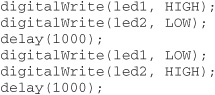
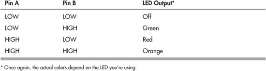
Figure 47-10 shows how to connect a bicolor LED to two pins of a microcontroller. To turn the LED off, put both pins LOW. To turn on one color or the other, put one of the pins HIGH.
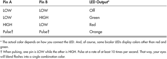
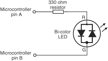
Figure 47-10 Connecting a bicolor LED to two I/O pins of a microcontroller. To display one of the colors, make its pin HIGH. Quickly alternating between the two pins produces a combination hue of the two colors combined.
As an example, the following code for the Arduino toggles between the two colors of a bicolor LED.
For the mixed-color effect, simply toggle between the two colors more quickly. Try reducing the delay from 1000 milliseconds (1 second) to 10 milliseconds (1/100th of a second).
Only one diode in a bicolor LED can be on at any time. But recall that in a tricolor LED, each diode has its own connection lead, so you can switch either on or off. You can also have both on at the same time, mixing the colors together. Figure 47-11 shows how to connect a tricolor (three-lead LED) to a microcontroller. Note that each diode in the LED gets its own current-limiting resistor. See tricolor.pde for a short demonstration program of toggling a tricolor LED from red to green to orange.
tricolor.pde

Figure 47-11 Connecting a tricolor LED to two I/O pins of a microcontroller. Either or both of the diodes can be turned on at once.
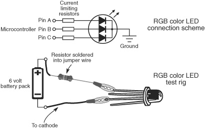
Figure 47-12 Connecting a multicolor (red-green-blue) LED to three I/O pins. Any color in the rainbow can be reproduced by altering the brightness of the three diodes.

And finally, a multi- or RGB-color LED has red, green, and blue diodes. These three primary colors can be displayed independently or in different combinations to produce many other colors. You use these the same as with a tricolor LED, except that you need a third microcontroller pin to control the additional color.
Figure 47-12 shows the connection scheme for a multicolor LED, plus a testing rig so you can experiment with how it works. Solder a current-limiting resistor (for example, 330 to 470 Ω) inline with the jumper wire. Connect the – terminal of the battery to the cathode lead of the LED, and then touch each of the three anode leads in turn to watch the colors.
Recall that you can mix colors by turning on more than one diode in the LED at a time. With a microcontroller with a PWM (pulse width modulation) output, you can vary the intensity of the light and create thousands of color combinations. The program rainbow-_led.pde, for the Arduino, shows how to use the analogWrite statement, which produces a PWM signal on specific pins of the microcontroller. We’ll be using digital pins D9, D10, and D11 for connecting to a multicolor LED (don’t forget the current-limiting resistors!).
rainbow_led.pde
To save space, the program code for this project is found on the RBB Online Support site. See Appendix A, “RBB Online Support,” for more details.
The hookup diagrams for the tri- and multicolor LEDs show common-cathode devices—that is, the cathode (negative) ends of all the diodes in the device are tied together. Multiple-color LEDs are also available in common-anode style, where the anode (positive) ends are linked together. The concepts behind using these are the same, though, of course, you must reverse the wiring. The LED is turned on when the cathode connection is brought LOW.
ON THE WEB: MORE STUPID LIGHT TRICKS
And there are more ways you can trick out your robot with light effects. Find these and other ideas on the RBB Online Support site:
![]() Using electroluminescent (EL) wire, fiber optics, and lasers
Using electroluminescent (EL) wire, fiber optics, and lasers
![]() Ornamenting your robot with self-contained body lighting (glow-in-the-dark sticks, rave lights, magnetic LED earrings)
Ornamenting your robot with self-contained body lighting (glow-in-the-dark sticks, rave lights, magnetic LED earrings)
![]() Outfitting your robot with different colors of cold cathode fluorescent tubes
Outfitting your robot with different colors of cold cathode fluorescent tubes
![]() Using passive decoration, such as decals, fluorescent paint jobs, and transfer film
Using passive decoration, such as decals, fluorescent paint jobs, and transfer film