Chapter 38
Using the PICAXE
Microcontrollers have become the favorite method for endowing robots with smarts. They’re single-chip computers complete with their own input/output ports and memory. They’re programmed from your PC, and, once programmed, they can be disconnected from the PC and operate on their own.
As detailed in Chapter 35, “Understanding Microcontrollers,” they are available in two basic flavors, referred to in this book as low-level programmable and integrated-language programmable. These loosely defined terms relate to the programming of the controller.
The PICAXE series of microcontrollers are among the better known, and most widely used, integrated-language programmable devices available today (another is the BASIC Stamp, detailed in its own chapter, next). The PICAXE isn’t just one controller; it’s a series of them, each with distinct capabilities. All are very affordably priced, and they are designed to operate with a minimum of external parts.
As you’ll read in this chapter, you can plug a PICAXE into a solderless breadboard and, with just a few resistors or so, have a complete microcontroller system ready for your use.
FYI
Be sure to see the chapters in Part 8 for numerous working examples of using the PICAXE in real-world applications. There are additional bonus examples and projects using the PICAXE on the RBB Online Support site. See Appendix A for details.
Understanding the PICAXE Family
PICAXE is a family of microcontrollers. Versions are available with as few as 8 pins and 5 I/O lines, to 40 pins and over 30 I/O lines. I won’t talk about each one here but, rather, I’ll take a look at two of the most commonly used devices.
The makers of the PICAXE, Revolution Education, update their product lineup from time to time, so you should always check their Web site at www.picaxe.co.uk for the latest. As of this writing, they have several series of PICAXE controllers, broadly classified into three segments: education, standard, and advanced.

They further categorize the PICAXE into M, M2, X, X1, and X2, with functionality varying between each. In this chapter you’ll read about the 08M, the smallest and least expensive of the bunch, but very capable anyway, and the 18M2, a “middle-of-the-road” controller that’s still very low in cost, offering additional features not found on its smaller siblings, and indeed, on many competing microcontrollers.
Figure 38-1 shows the pinouts for the 08M and 18M2. They differ not only in the number of physical pins on the chip, but in the ordering of the functions for the inputs and outputs. The 18M2 also supports some additional programming commands not found in the 08M. Several of these are outlined in this chapter, but the variations within the PICAXE chips—what features they support and what commands they’ll run—can be a point of confusion. See the PICAXE documentation for a full understanding of the differences and capabilities within each chip in the family.
For all PICAXE chips, it’s very important to remember the difference between the physical pins of the IC (called “legs” in the PICAXE documentation) and the names of the I/O lines. What’s referred to as Pin4 or C.4 is the name given to an I/O line, for example not the actual pin on the chip.
The reason for this is consistency in sharing programs across the different PICAXE chips. The functions available at the different physical pins (legs) of the chip can vary, meaning that physical pin 4 on one PICAXE controller may have a completely different function than physical pin 4 on another PICAXE.
The variation in pin assignments is caused by the architecture of the microcontrollers that PICAXE chips are based on. Each PICAXE starts life as a Microchip PICMicro controller. It’s made into a bona fide PICAXE by programming into it the language interpreter that takes your software and runs it once downloaded.
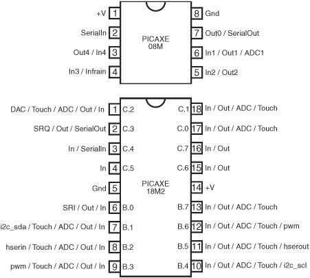
Figure 38-1 Pinout diagrams for the PICAXE 08M and 18M2 microcontrollers. There are other PICAXE chips available; refer to the PICAXE documentation for more details on the rest of the family.
When you purchase a PICAXE, you’re getting a PICMicro microcontroller that already has a core program included in it. When you download your own programs, they share space in the memory of the chip. When you delete your program, only your program is deleted; the language interpreter remains.
BASICS OF ALL PICAXE CONTROLLERS
All PICAXE chips require connections to power and ground. Except for some special low-voltage varieties, the PICAXE runs on power from 3 to 5.5 volts. It’s common to power the chip with a set of two or three AA or AAA batteries. This provides 4.5 volts when using nonrechargeable batteries. If using rechargeable batteries rated at 1.2 volts per cell, you’re better off using four cells, which provides a total of 4.8 volts.
![]()
Don’t power the PICAXE with more than 5.5 volts. Otherwise, the chip will likely be destroyed within seconds.
The PICAXE is programmed via a serial port connection from your PC. Any standard serial port will do. If your computer lacks a serial port, you can use a USB-to-serial adapter cable. One made specially for the PICAXE experimenter boards is sold by Revolution Education (their part number AXE027) and has a USB Type-A connector on one end and a “stereo”-style 1/8″ mini plug on the other.
All PICAXE controllers require at least two external resistors to function. The minimal circuit is illustrated in Figure 38-2, showing how the two resistors are used for the downloading process. Even when not downloading a program, the resistors must remain part of the circuit, or else the PICAXE will not behave correctly.
![]() The 22 kΩ series resistor limits current from the PC serial port to the chip.
The 22 kΩ series resistor limits current from the PC serial port to the chip.
![]() The 10 kΩ pull-down resistor prevents the SerialIn pin from floating, which can happen when the PICAXE is not actively connected to a serial port. If left floating, operation of the chip can become unstable.
The 10 kΩ pull-down resistor prevents the SerialIn pin from floating, which can happen when the PICAXE is not actively connected to a serial port. If left floating, operation of the chip can become unstable.
Additionally, on PICAXE chips that have a Reset pin you need to connect a 4.7 kΩ resistor to the +V power, as shown in Figure 38-3 (the switch is optional, but recommended; pressing it resets the controller). Finally, the 28- and 40-pin PICAXE chips can use an external resonator, which occupies two pins on the IC. Use a three-leg ceramic resonator, as shown.
In this book, I/O designations are referred to in the following way:

Figure 38-2 The minimal parts setup for all the PICAXE controllers consists of the microcontroller itself, plus two resistors used for downloading programs. The resistors must remain even when the download cable is removed.
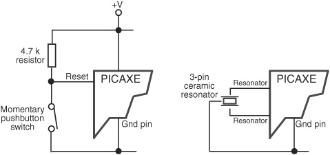
Figure 38-3 Additional components required on PICAXE chips that use a reset pin, and that require the use of an external resonator. The minimum operating speed is 4 MHz, but many PICAXE microcontrollers may be operated at between 8 and 64 MHz, depending on the chip.
![]() The physical pin numbers of the chips are largely ignored, unless otherwise specified. To indicate I’m talking about an actual pin on the chip, I’ll refer to it as a physical pin or a leg. Note that the PICAXE documentation uses the term leg.
The physical pin numbers of the chips are largely ignored, unless otherwise specified. To indicate I’m talking about an actual pin on the chip, I’ll refer to it as a physical pin or a leg. Note that the PICAXE documentation uses the term leg.
![]() The generic name for an I/O line is a pin, and they all have numbers. The way I/O pins are named differs depending on the version of the chip. The 08M uses the nomenclature Pin1, Pin2, and so on. (This is the more or less the same in the PICAXE documentation, except they use spaces between “Pin” and the number.) The 18M2 uses the nomenclature B.1, B.2, etc.
The generic name for an I/O line is a pin, and they all have numbers. The way I/O pins are named differs depending on the version of the chip. The 08M uses the nomenclature Pin1, Pin2, and so on. (This is the more or less the same in the PICAXE documentation, except they use spaces between “Pin” and the number.) The 18M2 uses the nomenclature B.1, B.2, etc.
![]() The function of an I/O line is referred to by the same name as the PICAXE documentation, except I remove the space between the name and any number that follows—for the 08M there’s Out1, ADC2, or In3. For the 18M2 I use the port.number nomenclature preferred for the M2 series: B.1, C.2, and so on.
The function of an I/O line is referred to by the same name as the PICAXE documentation, except I remove the space between the name and any number that follows—for the 08M there’s Out1, ADC2, or In3. For the 18M2 I use the port.number nomenclature preferred for the M2 series: B.1, C.2, and so on.
Note that many pins can perform multiple functions, and these functions are set in the microcontroller hardware. For example, on the 18M2 physical pin 18, which is designated C.1, can serve as a digital input or output, an analog-to-digital conversion input, or as a capacitance touch sensor input.
Output pins on the PICAXE can supply up to 20 milliamps (mA) of current, but the whole chip is limited to under 100 mA or so combined. If you’re working on a project using lots of light-emitting diodes, consider using a buffer driver IC, such as the ULN2003, between the PICAXE and the LEDs. See also Chapter 40, “Interfacing Hardware with Your Microcontroller or Computer,” for other approaches.
Finally, the PICAXE chips operate out of the box at 4 MHz, but all of the currently offered controllers can be set to operate at a minimum of 8 MHz. The X1 parts can go to 20 MHz, and the more advanced M2 and X2 parts can run at 32 MHz and 64 MHz, respectively. Specifics on chip speed are provided in the PICAXE manual.
INSIDE THE 08M
Let’s begin by taking a closer look at the 08M. Refer to Figure 38-1 for a pictorial layout of the pins.
![]() Three of its eight pins are dedicated for specific use—power, ground, and SerialIn—leaving the remaining five for input and output.
Three of its eight pins are dedicated for specific use—power, ground, and SerialIn—leaving the remaining five for input and output.
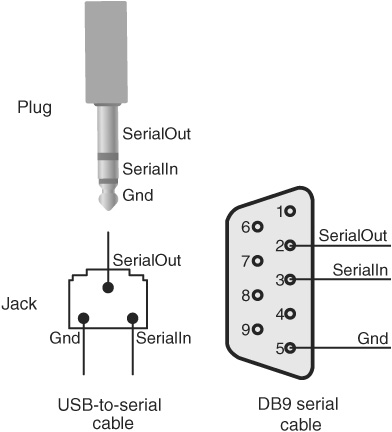
Figure 38-4 Download cable connections, for both the USB-to-serial cable and the standard nine-pin serial port PC connection. These match the connections in Figure 38-2.
![]() Pin3 (physical pin 4), labeled Infrain / In3, is an input only.
Pin3 (physical pin 4), labeled Infrain / In3, is an input only.
![]() Pin0 (physical pin 7) works as an output only. In addition to being a standard digital output (Out0), it is also used for special functions: SerialOut and Infraout. Both functions are detailed later in the chapter.
Pin0 (physical pin 7) works as an output only. In addition to being a standard digital output (Out0), it is also used for special functions: SerialOut and Infraout. Both functions are detailed later in the chapter.
![]() The remaining pins can serve as either inputs or outputs. Their respective functions are listed.
The remaining pins can serve as either inputs or outputs. Their respective functions are listed.
The basic programming connection diagram for the PICAXE (any chip) is shown in Figure 38-4, for both the USB-to-serial and DB-9 (9 pin) serial ports. Note the wire from SerialOut, the link back to your PC’s serial port. During programming, this I/O line is occupied, but it can be used as another output if you disconnect the download cable.
The 08M has limited memory available for programs. It contains 256 bytes of EEPROM both to store your downloaded programs and for use as nonvolatile memory—the data stay even when you unplug the chip from its power. Depending on the programming commands you use, there’s enough room for about 40 lines of code.
INSIDE THE 18M2
The 18M2 is among a newer generation of PICAXE chips that support numerous new features. As a result, it uses a different nomenclature to denote its various I/O pins. More of the pins on the M2 can serve multiple purposes: input, output, and more. Each I/O is described using a letter, which indicates the port, and a number, which indicates the specific pin of that port. For example, B.2 is port B, pin 2.
Refer to Figure 38-1 for a pictorial layout of the 18M2 pins. As with the 08M, the 18M2 has connections for power, ground, SerialIn, and SerialOut. All but a few of the I/O pins can be used as both inputs and outputs. This is set in software.
The 18M2 has about 2K bytes of space available for holding programs you download to it. Programs are stored in rewritable flash memory. Depending on the programming commands you use, there’s enough room for about 600 lines of code. There’s also an additional 256 bytes of EEPROM for nonvolatile data storage, handy for data-logging and other tasks.
Programming the PICAXE
All PICAXE controllers may be programmed using editor software provided for free by Revolution Education. Check their Web site at www.picaxe.co.uk for details. Versions of the program editor are available for Microsoft Windows (Windows 98 and later), Macintosh OS X, and Linux.
If you use a USB cable for programming, you will also need an appropriate USB driver for your operating system. These, too, are provided free of charge. Note that the USB or serial port connection does not provide power for the device.
The program editor, shown in Figure 38-5, supports the PICAXE BASIC language. Here you can write, save, and print your programs. PICAXE programs are stored as standard ASCII files, so they can be opened by any text editor. The default file extension is .bas.
The program editor has some nifty features you’ll want to try out:
![]() Environment settings are made using the Options button, where (among other things) you specify the particular PICAXE microcontroller you’re using and the serial port on your computer that’s connected to the chip.
Environment settings are made using the Options button, where (among other things) you specify the particular PICAXE microcontroller you’re using and the serial port on your computer that’s connected to the chip.
![]() The Flowchart tool lets you create programs visually. Clicking on the Flowchart button opens a separate editing window, where you build programs using graphical objects.
The Flowchart tool lets you create programs visually. Clicking on the Flowchart button opens a separate editing window, where you build programs using graphical objects.
![]() Mistakes in your program are flagged using the Syntax checker. Errors are flagged by line, where you can make necessary corrections.
Mistakes in your program are flagged using the Syntax checker. Errors are flagged by line, where you can make necessary corrections.
![]() Numerous wizards help in constructing several kinds of programming code. Examples include a tune wizard, used to build a progression of musical notes, a datalogger wizard for use in storing information collected over long periods of time, and others.
Numerous wizards help in constructing several kinds of programming code. Examples include a tune wizard, used to build a progression of musical notes, a datalogger wizard for use in storing information collected over long periods of time, and others.
![]() The built-in simulator will run through your code and show you how it’ll function inside the PICAXE. You see how memory is used and what effect your code has on the I/O pins of the controller.
The built-in simulator will run through your code and show you how it’ll function inside the PICAXE. You see how memory is used and what effect your code has on the I/O pins of the controller.

Figure 38-5 The PICAXE programming editor. From the editor you can write, edit, simulate, compile, and download your PICAXE programs.
Before you can send your programs to the PICAXE, they must be compiled. This is done in the editor by clicking on the Program button. Syntax errors are flagged, and if any are found, compiling stops. When you have successfully compiled the program, it is automatically downloaded to the PICAXE.
Core Language Syntax
The PICAXE uses its own unique flavor of the BASIC language, referred to as PICAXE BASIC. Like most any other programming language, it is composed of a series of commands used together in a specific, orderly way. The way the commands are assembled is called a syntax, and it’s important that you use the correct syntax to form your PICAXE programs, or else they will not work.
COMMENTS
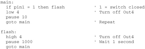
You can include remarks for yourself and others who read your code. The remarks are ignored when the program is compiled, so it doesn’t matter how many you include. Commands are marked with the’ (apostrophe) character, as in:
![]()
VARIABLE AND PIN/PORT DEFINITIONS
PICAXE uses variables to store information during program execution. Most of the PICAXE chips provide several ways to store variables, chief among them a set of 14 (or more, depending on the chip) general-purpose variables, each of which can hold a byte of data.
Though the general-purpose variables are each byte sized, the 8 bits that make up each byte can be individually manipulated, allowing you to store simple on/off information much more efficiently. The PICAXE documentation provides details on how to do this for the various families of chips.
You can manipulate I/O pins as a group or individually. I’ll defer to the PICAXE documentation for how to control groups of pins together (especially as it varies from chip to chip), but to do it for an individual I/O pin you specify the action you want, and the pin designation. For example, to make Out4 on the 08M HIGH (turn it on), you’d use
high 4
and for the 18M2, you’d use
high B.4
USING SYMBOLS
Another form of variable is the symbol. A symbol isn’t a true variable—it’s not used as temporary data space by the microcontroller; rather, it’s a convenience during programming. It lets you refer to the various parts of the PICAXE architecture using your own terms, making your programs easier to read and understand. When the program is compiled, the PICAXE editor exchanges each instance of your term with the actual value.
To use a symbol, you first declare it at the top of your program. The syntax is simple
symbol yourname = PICAXE_name
where yourname is the term you want to refer to something by, and PICAXE_name is the actual name for a port or pin. Example:
symbol LED = 4
makes LED the same as Out4. You can then use the term LED in your program every time you want to do something to Out4. To make it HIGH, you’d use
high LED
That’s the same as
high 4
PROGRAM CONSTRUCTION
The PICAXE doesn’t have a lot of prerequisites for its programs. A program can be just one line long, though most use the following construction
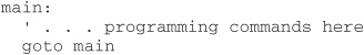
Main: is a label, a way for you to reference different parts of your program. Labels are formed using a single word, followed by a colon.
The preceding construction creates an endless loop, which is quite typical in robotics. The goto main command tells the PICAXE to pick up where it is and go to the identified label. Your programming commands, which are contained between the loops, are repeated over and over again.
It’s also common to devise special subroutines in your program that do certain tasks, sometimes just once when the program first starts, or at specific times depending on the outcome of the computations made in the main: loop. For instance:

This code first branches off to a subroutine named init. Even though this subroutine appears at the bottom of the program, the gosub (which means goto subroutine) tells the program to first perform the steps in init:. Note the return command at the end of the init: subroutine. This informs the program that the subroutine is finished and tells it to go back to the line following the gosub command.
As before, the main body of the program is within the main: loop.
FLOW CONTROL
Flow control commands tell your program what to do next. You’ve already seen two forms of flow control: the goto and gosub commands. These are similar commands in that they both unconditionally branch execution to another part of the program.
Another type of flow control command provides conditional branching. It’s the if command, which is used in conditional expressions that execute one part of the program if condition A exists, and another part of the program if condition B exists.
Using the if Command
The if command, which is always used in conjunction with the then keyword, conditionally branches execution depending on the outcome of an expression. The basic syntax is:
if Expression then Label
Expression is the condition that must resolve to a True or False statement, and Label is an identified label elsewhere in the program that the execution is to jump to. An example of a typical Expression is checking the value of an input pin against an expected value:
if Pin4 = 1 then flash
If the value of Pin4 is equal to 1 (the expression is True), then the program is expected to jump to the flash label. As detailed in the previous section, this label is identified by the label name, followed by a colon, like this:
![]()
The if expression can use a number of logical operators:

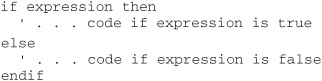
PICAXE BASIC supports numerous variations of the if command. For example, you can insert the code to execute immediately after the if command using the format
![]()
And by using the else keyword you can provide special instructions on what to do if the expression fails (is false):
Consult the PICAXE manual for these and other variations.
More on Using the goto and gosub Commands
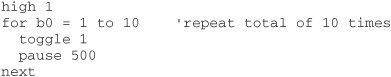
Let’s take a closer look at the goto and gosub commands. As we’ve seen, goto is most often used to create endless loops:
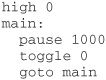
In this program, Out0 is set to 1 (HIGH). The program then pauses for 1000 milliseconds (1 second) and then toggles Out0 to its opposite state. The goto command makes the program jump back to the main label. Assuming the Out0 pin is connected to an LED, it would flash on and off.
Gosub is similar to goto, except that when the code at the label is done, the program returns to the command immediately after gosub. Here’s an example:
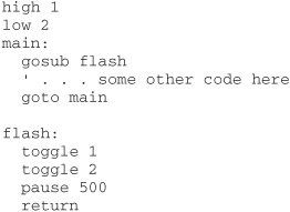
The program begins by setting I/O pin 1 to HIGH and I/O pin 2 to LOW. It then “calls” the flash routine, using the gosub command. The code in the flash routine toggles I/O pins 1 and 2 from their previous state, waits half a second, and then returns with the return flow control command.
Using the for Command
Another type of flow control command is for, and it is used with the to and next keywords. Used together, they control a counter that repeats your code a set number of times. The syntax for the for command is:
![]()
Variable is a variable that is used to contain the current count of the for loop. StartValue is the initial value to begin with; EndValue marks the value to count to. The loop is broken (and the rest of the program can then run) when Variable exceeds EndValue. For example, if you use the following
for b0 = 1 to 10
the loop starts with 1 in variable b0 and counts to 10. The for loop is repeated 10 times. You don’t have to start with 1, and you can use an optional step keyword to tell the for loop that you want to count by 2s, 3s, or some other value:
for b0 = 5 to 7
counts from 5 to 7.
For loops are used to execute whatever programming lies between the for and next commands. Here’s a simple example:
PICAXE Functions for Robotics
Much of the power of the PICAXE comes in its set of built-in commands that reduce the complexity of programming. Most are designed to control some activity of the chip, for example, to produce sound through one of the output pins, or to produce timed signals to control one or more R/C servo motors. I’ll briefly review the special functions most useful for robotics, but you’ll want to look over the PICAXE manual for more.
![]() button. The button command momentarily checks the value of an input and then branches to another part of the program if the button is LOW (0) or HIGH (1). The button command lets you choose which input pin to examine, the “target state” you are looking for (either 0 or 1), and the delay and rate parameters that can be used for such things as switch debouncing.
button. The button command momentarily checks the value of an input and then branches to another part of the program if the button is LOW (0) or HIGH (1). The button command lets you choose which input pin to examine, the “target state” you are looking for (either 0 or 1), and the delay and rate parameters that can be used for such things as switch debouncing.
![]() debug. The PICAXE program editor has a built-in terminal that displays the result of bytes sent from the chip back to the PC. Of course, you need to have the serial/USB cable connected to receive anything. The debug command displays information that may be useful during testing.
debug. The PICAXE program editor has a built-in terminal that displays the result of bytes sent from the chip back to the PC. Of course, you need to have the serial/USB cable connected to receive anything. The debug command displays information that may be useful during testing.
![]() infrain/infrain2/irin and infraout/irout. These commands are used to receive and send (respectively) infrared remote control signals that use the Sony SIRC protocol. Infrain, infrain2, and irin are used in conjunction with an infrared receiver/modulator (see Chapter 41, “Remote Control Systems”), which detects the signals from the remote and converts them to on/off pulses. Conversely, infraout is used to produce Sony-compatible IR signals.
infrain/infrain2/irin and infraout/irout. These commands are used to receive and send (respectively) infrared remote control signals that use the Sony SIRC protocol. Infrain, infrain2, and irin are used in conjunction with an infrared receiver/modulator (see Chapter 41, “Remote Control Systems”), which detects the signals from the remote and converts them to on/off pulses. Conversely, infraout is used to produce Sony-compatible IR signals.
![]() servo. The servo command (and its lieutenant, servopos) allows you to control the operation of an R/C servo motor. With the command you specify the output port to use, along with the position of the motor, in tenths of a microsecond. Valid values are from 75 to 225 (note: you must use whole numbers only).
servo. The servo command (and its lieutenant, servopos) allows you to control the operation of an R/C servo motor. With the command you specify the output port to use, along with the position of the motor, in tenths of a microsecond. Valid values are from 75 to 225 (note: you must use whole numbers only).
![]() sound. The sound command is used to generate tones primarily intended for audio reproduction. You can set the I/O pin, note frequency (in Hertz), and duration. You can string a series of notes (each with a separate duration) to produce simple monophonic music or sound effects.
sound. The sound command is used to generate tones primarily intended for audio reproduction. You can set the I/O pin, note frequency (in Hertz), and duration. You can string a series of notes (each with a separate duration) to produce simple monophonic music or sound effects.
![]() pause. The pause command is used to delay execution by a set amount of time. To use pause you specify the number of milliseconds (thousandths of a second) to wait. For example, pause 500 pauses for 500 milliseconds, or half a second.
pause. The pause command is used to delay execution by a set amount of time. To use pause you specify the number of milliseconds (thousandths of a second) to wait. For example, pause 500 pauses for 500 milliseconds, or half a second.
![]() pulsin. The pulsin command measures the width of a single pulse with a resolution of 10 microseconds (10 μs), when using the PICAXE at the default 4-MHz speed. You can specify which I/O pin to use, whether you’re looking for a 0-to-1 or 1-to-0 transition, as well as the variable in which you want to store the result. Pulsin is handy for measuring time delays in circuits, such as the return “ping” of an ultrasonic sonar.
pulsin. The pulsin command measures the width of a single pulse with a resolution of 10 microseconds (10 μs), when using the PICAXE at the default 4-MHz speed. You can specify which I/O pin to use, whether you’re looking for a 0-to-1 or 1-to-0 transition, as well as the variable in which you want to store the result. Pulsin is handy for measuring time delays in circuits, such as the return “ping” of an ultrasonic sonar.
![]() pulsout. Pulsout is the inverse of pulsin: with pulsout you can create a finely measured pulse with a duration of between 10 μs and 65,535 μs (the resolution is increased when running the PICAXE at speeds over 4 MHz). The pulsout command is ideal when you need to provide accurate waveforms.
pulsout. Pulsout is the inverse of pulsin: with pulsout you can create a finely measured pulse with a duration of between 10 μs and 65,535 μs (the resolution is increased when running the PICAXE at speeds over 4 MHz). The pulsout command is ideal when you need to provide accurate waveforms.
![]() readadc. The readadc command reads a linear voltage at any ADC (analog-to-digital converter) input pin. The voltage is then converted to an 8-bit (0 to 255) digital equivalent. A similar command, readadc10, provides a 10-bit (0 to 1023) resolution.
readadc. The readadc command reads a linear voltage at any ADC (analog-to-digital converter) input pin. The voltage is then converted to an 8-bit (0 to 255) digital equivalent. A similar command, readadc10, provides a 10-bit (0 to 1023) resolution.
![]() serin and serout. The s erin and serout commands are used to send and receive asynchronous serial communications using any output pin. They represent one method for communicating with other devices. One application of serout is to interface a liquid-crystal display (LCD) to the PICAXE.
serin and serout. The s erin and serout commands are used to send and receive asynchronous serial communications using any output pin. They represent one method for communicating with other devices. One application of serout is to interface a liquid-crystal display (LCD) to the PICAXE.
![]() shiftin and shiftout. These commands are used in two- or three-wire synchronous serial communications. These commands are useful when communicating with a variety of external hardware, including serial-to-parallel shift registers and serial analog-to-digital converters.
shiftin and shiftout. These commands are used in two- or three-wire synchronous serial communications. These commands are useful when communicating with a variety of external hardware, including serial-to-parallel shift registers and serial analog-to-digital converters.
![]() parallel tasking. The 18M2 and other M2 series chips are capable of running up to four separate programs—called tasks—at once. Internally, the microcontroller divides its attention among the tasks, spending small slices of time with each one. Parallel tasking is especially handy in robotics where you want to monitor several different things at the same time, such as a set of bumper switches plus infrared and ultrasonic sensors.
parallel tasking. The 18M2 and other M2 series chips are capable of running up to four separate programs—called tasks—at once. Internally, the microcontroller divides its attention among the tasks, spending small slices of time with each one. Parallel tasking is especially handy in robotics where you want to monitor several different things at the same time, such as a set of bumper switches plus infrared and ultrasonic sensors.
Example: Controlling an RC Servo with the PICAXE
The PICAXE contains several commands designed directly for use on R/C servo motors. The commands are servo, which sets up the PICAXE to operate a servo, and servopos, which moves the servo depending on the position value you give it.
Figure 38-6 shows a typical connection diagram between PICAXE and servo, with an optional 330 Ω resistor in series on the signal line. This resistor is recommended in the PICAXE documentation and limits the current draw from the servo, should it go haywire. Note the separate battery supply for the servo and the connected ground wires shared between the PICAXE and the servo. Both are required for proper operation.
Code is straightforward:
![]()

Figure 38-6 Connection diagram for attaching a standard R/C servo to a PICAXE. You must power the servo from its own 6-volt battery. Be sure to connect together the ground (Gnd) leads of the PICAXE battery and the servo battery.
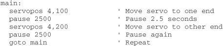
The servo is connected to the Out4 pin of the PICAXE 08M. The servo is initialized with a value of 150, which equates to 1500 microseconds, or 1.5 milliseconds. The main body of the program then repeats a loop where the servo is positioned from one end to the end, pausing between each transit for 2-1/2 seconds.
Example: Reading Buttons and Controlling Outputs
A common robotics application is reading an input, such as a switch, and controlling an output, such as an LED or motor. The following example shows a simple method of reading the state of a switch, and then displaying the result on an LED. The switch is connected to pin In1; the LED to pin Out4. Figure 38-7 shows a connection diagram.
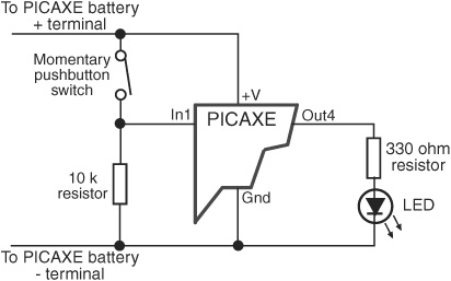
Figure 38-7 Connection diagram for demonstrating a push-button input (with debounce) and LED output. The push-button switch is a normally open momentary type.
The code notes when the switch closes and produces a 1 (HIGH) on pin In1. The LED connected to Out4 lights up, and the program pauses for 1 second before continuing.