
Chapter 30
Building Robot Electronics—the Basics
In previous chapters you learned all about the mechanics of robots, including their construction, motors and wheels, and power systems. In this chapter you’ll discover the electronics that endow bots with the appearance of life. In this and future chapters you’ll find out ways to use modern (but still inexpensive) advances in electronics to create fully programmable robots able to truly think on their own. It’s an exciting endeavor, so let’s get started.
FYI
If you’re absolutely new to electronics you may wish to first read the lessons in My First Robot (see Appendix A, “RBB Online Support,” for details). You’ll learn the very basic concepts of electricity and electronics as you build a simple robot pet that explores its surroundings by touch.
Tools for Electronics You Should Have
Compared to mechanical construction, you need relatively few tools to build the electronic centerpieces of your robots. You can always spend lots and lots of cash for all kinds of testing equipment and specialized electronic gear, but what follows are the basics that will get you started.
MULTIMETER
A multimeter, also called a volt-ohm meter, VOM, or multitester, is used to test voltage levels and the resistance of circuits—among other things. This moderately priced tool (see Figure 30-1) is the basic prerequisite for working with electronic circuits of any kind. If you don’t already own a multimeter, you should seriously consider buying one. The cost is minimal, considering its usefulness.

Figure 30-1 A digital multimeter checks resistance, voltage, and current. This model also performs simple checks of a number of common electronic components, including capacitors, diodes, and transistors.
There are many multimeters on the market today. A meter of intermediate features and quality is more than adequate. Meters are available at RadioShack and most online electronics outlets. Shop around and compare features and prices.
Digital or Analog
There are two general types of multimeters available today: digital and analog. The difference is not in the kinds of circuits they test, but in how they display the results. Digital multimeters, which are now the most common, use a numeric display not unlike a digital clock. Analog meters use the more old-fashioned—but still useful—mechanical movement with a needle that points to a set of graduated scales.
Automatic or Manual Ranging
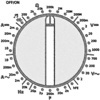
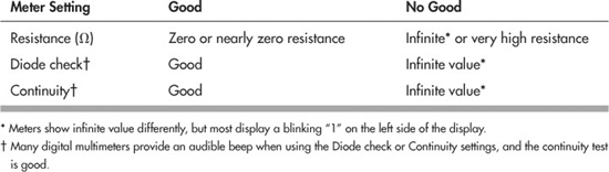
Many multimeters require you to select the range before it can make an accurate measurement. For example, if you are measuring the voltage of a 9-volt battery, you set the range to the setting closest to, but above, 9 volts. With most meters it is the 20-or 50-volt range. Because you need to select the range, there are lots of options on the dial, but in reality these options are really just variations on a theme. The meter is easier to use than it looks.

Autoranging meters don’t require you to do this, so they are inherently quicker to use. When you want to measure voltage, for example, you set the meter to volts (either AC or DC) and take the reading. The meter displays the results in the readout panel.

For the sake of completeness, the examples in this book that explain how to use a meter assume you have a manual (nonautomatic) ranging model. If yours has automatic ranging, then just skip the step that says to dial in the upper range of your expected measurement.
Accuracy
The accuracy of a meter is the minimum amount of error that can occur when taking a specific measurement. For example, the meter may be accurate to 2000 volts, plus or minus 1 percent. A 1 percent error at the kinds of voltages used in robots—typically, 5 to 12 volts DC—is only 0.1 volts. Not enough to quibble about.
Digital meters have another kind of accuracy: the number of digits in the display determines the maximum resolution of the measurements. Most digital meters have three and a half digits, so they can display a value as small as 0.001—the half digit is a “1” on the left side of the display.
Functions
Digital multimeters vary greatly in the number and type of functions they provide. These functions are selectable by rotating a dial on the front of the meter. At the very least, all standard multimeters let you measure AC and DC voltage, DC amperage, and resistance.
The maximum ratings of the meter when measuring volts, milliamps, and resistance also vary. For most applications, the following maximum ratings are more than adequate:
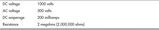
One very important exception to this is when you are testing the amount of current draw from motors. Many DC motors draw in excess of 200 milliamps.
Better multimeters have a separate DC amperage input that allows readings of up to 10 amps (sometimes as high as 20 amps). If you have the budget for it, I highly recommend that you get a meter with this feature. In most cases, it’s a separate input on the front of the meter and is clearly labeled, like that in Figure 30-2.
The high-amperage input may or may not be fuse-protected; if it is fuse-protected and you exceed the current rating for the input, a fuse will blow and you’ll have to get it replaced. On some inexpensive multimeters the inputs are not fused, and exceeding the maximum ratings could result in permanent damage to the device. So be careful!
Meter Supplies
Multimeters come with a pair of test leads, one black and one red. Each is equipped with a pointed metal probe. The quality of the test leads included with the multimeter is usually minimal, so you may want to purchase a separate set that’s better. The coiled kind is handy; the test leads stretch out to several feet, yet recoil to a manageable length when not in use.
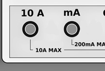
Figure 30-2 For robotics work you’ll want a multimeter with a high amperage (10 amps or higher) input. You use this to easily test the current draw of motors, among other tasks.
Standard point-tip leads are fine for most routine testing, but some measurements may require that you use a clip lead. These attach to the end of the regular test leads and have a spring-loaded clip on the end. You can clip the lead in place so your hands are free to do other things. The clips are insulated with plastic to prevent short circuits.
Using the Meter: The Basics
To use your multimeter, first set it next to whatever circuit you’re testing. Make sure it’s close enough so the test leads reach the circuit without any risk of pulling either the meter or the circuit into your lap. Then start with this:

1. Plug in the test leads; the black lead of your meter goes into the – or COM jack, and the red lead of your meter goes into the + or labeled function jack (the label may be something like VΩmA, which represents the kinds of tests you can do when the lead is inserted into that jack—in this case, voltage (V), resistance (Ω), and low-milliamp (mA) current testing.
2. Check for proper meter operation by doing a continuity test. This involves selecting one of the following operating modes. Depending on the features of your meter, choose Resistance (Ω), Diode check, or Continuity. If using Resistance and the meter is not autoranging, choose the lowest Ω setting.
Touch the metal tips of the test probe together. If the meter is functioning properly—the battery is good, the test leads are not broken—the results should be as shown here:
Once the meter has checked out, select the desired function and range, and apply the leads to the circuit under test.
What?!? The meter doesn’t pass its simple continuity test? The reasons could be simple and easy to fix: check that the internal battery is good. Replace as needed. Inspect the test leads for breaks. If the metal prongs of the leads are old, they could be corroded or rusted. Clean or replace. And finally, if the meter is internally fused, the fuse could be blown. Try the spare.
Using the Meter: Testing a Battery
You can use your multimeter to test batteries and other low-voltage DC power sources. Merely as an example to get you started, here are the steps:
1. With the meter on, dial to the DCV (DC volts) setting. If your meter is not autoranging, select a range that is one step higher than the expected voltage; for most robot tasks this will be 20 volts or less.
2. Ensure the test leads are plugged into the proper jacks, as detailed in the previous section “Using the Meter: The Basics.”
3. Touch the black lead to the negative (−) terminal of the battery or pack; touch the red lead to the positive (+) terminal.
![]()
4. Note the value displayed by the meter. If the battery (or pack) is good, the voltage should be close to the expected value—for example, an AA alkaline battery should be about 1.5 volts, give or take 0.1 or 0.2 volts.
![]()
5. For grins, switch the test leads so that black goes to the + battery terminal and red goes to −. Note the voltage again; it should now be a negative value, indicating that the polarity of the test connection to the battery is reversed.
Using the Meter: Verifying the Value of a Resistor
Another common use of a multimeter is verifying the value of a resistor. Here’s how.
1. From your parts bin, select any four-banded resistor with the color brown as its third band. This will ensure the resistor is between 100 and 990 ohms. (Resistors and their values and markings are discussed in more detail in Chapter 31.)
2. Refer to the resistor color code table in Appendix D, “Electronics Reference,” to look up the value of the resistor. For example, if the first three color bands are orange-orange-brown, the indicated value of the resistor is 330 Ω.
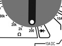
3. With the meter on, dial to the Ω setting. If your meter is not autoranging, select a range that is one step higher than the expected reading. For instance, if the ranges are 2, 20, 200, 2000, and so forth, select 2000 (2k), as it is one step higher than the expected value of 330 Ω.

4. Ensure the test leads are plugged into the proper jacks, as detailed in the previous section “Using the Meter: The Basics.”
5. With the resistor resting on the table or workbench, apply the test leads to either side of the resistor. Be sure not to touch the metal of the test leads, or else the natural conductivity of your skin will influence the result.
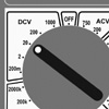
6. Read the value on the meter. See Figure 30-3 for an example:
So the resistor doesn’t read exactly what it should? There’s no cause for alarm. The fourth band on a resistor with four color bands indicates its tolerance, or how far off the printed value it can be from the actual value. A gold band indicates 5 percent tolerance; a silver band, 10 percent tolerance. If the resistor is 330 Ω with 10 percent tolerance, its reading on the multimeter can range from about 300 to 360 Ω.
Meter Safeguards, Good Operating Habits
When using a meter, even on low-voltage circuits, observe these best operating habits:
![]() Never hold the test probes by their metal part. Not only can this give you a nasty shock when testing AC household current, but your skin resistance can alter the test results.
Never hold the test probes by their metal part. Not only can this give you a nasty shock when testing AC household current, but your skin resistance can alter the test results.
![]() On each use of the meter, test its basic operating status with the continuity check detailed previously.
On each use of the meter, test its basic operating status with the continuity check detailed previously.
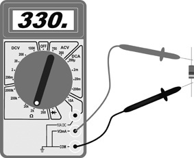
Figure 30-3 Reading the value of a resistor. Be sure not to touch the test probes, or the resistance of your skin will influence the result. When using a meter without autoranging, adjust the range dial just above the expected value.
![]() None of the projects in this book involve working directly with AC household current—everything is battery-powered. Should you wish to use your multimeter with an AC circuit, be sure to consult the instruction manual that came with the meter for important safety precautions.
None of the projects in this book involve working directly with AC household current—everything is battery-powered. Should you wish to use your multimeter with an AC circuit, be sure to consult the instruction manual that came with the meter for important safety precautions.
![]() Be very careful when selecting the operating mode of the meter. Never accidentally set the meter to read resistance and then test a voltage source. Your meter could be damaged otherwise or, at the least, burn out a fuse if it is so equipped.
Be very careful when selecting the operating mode of the meter. Never accidentally set the meter to read resistance and then test a voltage source. Your meter could be damaged otherwise or, at the least, burn out a fuse if it is so equipped.
![]() Turn off the meter when you’re done with it. This preserves battery life.
Turn off the meter when you’re done with it. This preserves battery life.
ON THE WEB: USING A LOGIC PROBE
Another handy tool for testing electronic circuits is the logic probe, so called because it verifies signals used in logic circuits (anything that deals with digital 0s and 1s, LOWs and HIGHs). These kinds of circuits include microcontrollers. I’ve prepared a free “Logic Probe 101” article on the RBB Online Support site (see Appendix A) that provides more information.
SOLDERING PENCIL
You can build robots without owning a soldering pencil, but it’s darned difficult to do anything more advanced than just put together basic kits. Even if you never plan to make your own circuit boards for your robots, you still need a soldering pencil for basic electronic chores, such as attaching wires to motors. My trusty soldering pencil is shown in Figure 30-4. I’ve had it for years, and I have built many robots with it.
Note that I’ve called it a soldering pencil, not the more old-fashioned “soldering iron.” For most electronics work these days, you want a slim-line modular soldering pencil. It’s smaller than the soldering iron your dad (or granddad) used to build the family’s Heathkit color TV kit way back when, and it’s designed specifically for the more delicate components common in modern electronics.
Not only do you want a soldering pencil, you really want the kind that lets you change the tip and heating element. Why? These are the parts that, over time, wear out. Rather than buy a whole new soldering pencil, you only have to buy replacement parts.
Figure 30-4 Soldering station with adjustable heat output. This model does not have a temperature indicator, but you can infer it by adjusting the output to where it just begins to melt solder. Remember that different compositions of solder have different melting points. (Photo courtesy Cooper Tools)
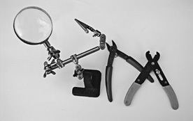
Figure 30-5 Trio of the most used tools for working with electronics: a vise or “third hand” (magnifier optional, but handy), flush wire cutters, and wire strippers.
For routine electronic work, you should get a soldering pencil with a 25-to 30-watt heating element. Anything higher may damage electronic components. You can use a 40-or 50-watt element for wiring switches, relays, and power transistors. If you can afford it, opt for a model with a temperature dial. They cost a bit more, but they’re far more flexible.
See the section “How to Solder,” later in this chapter, for a step-by-step guide on soldering.
HAND TOOLS FOR ELECTRONIC CONSTRUCTION
You need just a few hand tools for electronic construction. The ones described here will fill your electronic toolbox quite nicely. All of these tools are inexpensive. The first three on the list, which are among the most used tools for electronic construction, are shown in Figure 30-5.
![]() Flush wire cutters, sometimes referred to as “nippy” cutters. These let you cut off wire flush with the surface of a circuit board.
Flush wire cutters, sometimes referred to as “nippy” cutters. These let you cut off wire flush with the surface of a circuit board.
![]() Wire strippers for smaller-gauge wire. Be sure it can handle between 18-and 26-gauge wire (the higher the number, the smaller the diameter of the wire). Most electronic hookup wire is 22 gauge. The stripper should have a dial that lets you select the gauge of wire you are using.
Wire strippers for smaller-gauge wire. Be sure it can handle between 18-and 26-gauge wire (the higher the number, the smaller the diameter of the wire). Most electronic hookup wire is 22 gauge. The stripper should have a dial that lets you select the gauge of wire you are using.
![]() Solder clamp or vise. The clamp or vise serves as a “third hand,” holding together pieces to be soldered, so you are free to work the soldering pencil and feed the solder. One with a built-in magnifying glass is nice. The ones with simple alligator clips are the least expensive, but they do the job.
Solder clamp or vise. The clamp or vise serves as a “third hand,” holding together pieces to be soldered, so you are free to work the soldering pencil and feed the solder. One with a built-in magnifying glass is nice. The ones with simple alligator clips are the least expensive, but they do the job.
![]() Set of flat-bladed and Phillips screwdrivers, including sizes #1 and #0.
Set of flat-bladed and Phillips screwdrivers, including sizes #1 and #0.
![]() Small needle-nose pliers.
Small needle-nose pliers.
![]() Dental picks. These are ideal for scraping, cutting, forming, and gouging into things. You can buy these surplus.
Dental picks. These are ideal for scraping, cutting, forming, and gouging into things. You can buy these surplus.
![]()
Always wear eye protection when using flush wire cutters or, for that matter, any wire-cutting tool. It’s quite common for wires to literally shoot out at high velocity when cut. You don’t want anything flying into your eyes.
Making Electronic Circuits—the Basics
You have at your disposal numerous ways to construct the electronic circuits for your robots. Those designs involving only switches and batteries and motors can simply be wired together, one to the other, and there is no need to centralize the components in a single place. Options include:
![]() Solderless breadboard. Quickly and easily construct circuits by plugging components into sockets on a plastic board. No soldering necessary. See Chapter 32, “Using Solderless Breadboards” for more information.
Solderless breadboard. Quickly and easily construct circuits by plugging components into sockets on a plastic board. No soldering necessary. See Chapter 32, “Using Solderless Breadboards” for more information.
![]() Permanent circuit board. Select from among several methods for soldering parts to build a permanent circuit. You can use generic boards that accept common components, or design your own printed circuit board (PCB). See Chapter 33, “Making Circuit Boards” for details.
Permanent circuit board. Select from among several methods for soldering parts to build a permanent circuit. You can use generic boards that accept common components, or design your own printed circuit board (PCB). See Chapter 33, “Making Circuit Boards” for details.
![]() Wire wrapping. Use a low-cost tool to interconnect electronic components with very fine wire. See how in Chapter 33.
Wire wrapping. Use a low-cost tool to interconnect electronic components with very fine wire. See how in Chapter 33.
Understanding Wires and Wiring
Almost every electronic circuit uses wire of one kind or another. Wiring is a science all to itself, but we’ll concentrate just on three main aspects: insulation, gauge, and conductor type.
INSULATION
Most of the wire used in building robot electronics is insulated with a plastic covering. This keeps one wire from touching another and causing a short circuit. Apart from esoteric aspects about insulation, the most important is its color. Get into the habit of using different-color wiring to denote what it’s being used for in your circuit. For example, red wire is often used for the + (positive) battery connection; black wire for the − (negative) connection.
GAUGE
The thickness, or gauge, of the wire determines its current-carrying capabilities. Generally, the larger the wire, the more current it can pass without overheating and burning up.
See Appendix D, “Electronic Reference,” for common wire gauges and the maximum accepted current capacity, assuming reasonable wire lengths of 5 feet or less. When you are constructing circuits that carry high currents, be sure to use the proper gauge of wire. Conversely, there’s no need to use wires that are way too large for their job. That just makes things bulkier and harder to solder together.
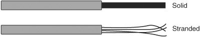
Figure 30-6 Types of hookup wire: solid and stranded. Each has its place. Solid conductor wire is ideal for use with solderless breadboards. Stranded wire is good for general jobs.
CONDUCTOR TYPE
Wire is made of one or more strands of metal, as depicted in Figure 30-6.
![]() Single-strand wire has just one metal conductor. It’s said to be single stranded, or solid conductor.
Single-strand wire has just one metal conductor. It’s said to be single stranded, or solid conductor.
![]() Multiple-strand wire has many conductors and is said to be stranded. For any given wire gauge the conductors in stranded wire are small. When banded together, the individual strands make up the gauge of the wire.
Multiple-strand wire has many conductors and is said to be stranded. For any given wire gauge the conductors in stranded wire are small. When banded together, the individual strands make up the gauge of the wire.
Which is better? Both—it depends on the application. Solid wire is commonly used when building circuits using a solderless breadboard. It’s cheaper to make, so the wire is less expensive. It’s also easier to solder. Stranded wire is more flexible and doesn’t break as easily when it’s repeatedly flexed. It can also carry a bit more current, per gauge, than solid conductor wire.
How to Solder
Few electronic projects can be assembled without soldering wires together. Soldering sounds and looks simple enough, but there’s a bit of science to it. If you are unfamiliar with soldering, or you need a quick refresher course, read the primer on soldering fundamentals provided in this section.
SOLDERING TOOLS YOU NEED
Good soldering means having the proper tools. If you don’t have them already, you can purchase them at RadioShack or most any electronics store. Let’s review the soldering-related tools you need.
We’ve already introduced the soldering pencil earlier in the chapter. See Figure 30-7 for a description of the pencil’s main parts. Be sure to get one with a three-prong power cord. This provides important grounding of the tool, which is needed for safety.
Stand
If your soldering pencil doesn’t come with a stand, be sure to get one. They’re used to keep the soldering pencil in a safe, upright position. You should never simply lay a hot soldering pencil down on your work table.
Sponge
Keep a damp (never dry) sponge by the soldering station. Be sure to keep it wet. Use the sponge to wipe off globs of solder that may remain on the tip. Otherwise, the glob may come off while you’re soldering and ruin the connection. In a pinch, you can substitute a wetted and folded-up paper towel or napkin. Be sure it stays wet—you don’t want it to catch fire when you try to clean the soldering tip against it!
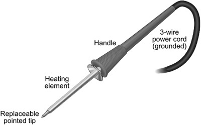
Figure 30-7 Parts of the soldering pencil. Be sure yours is a three-wire grounded model. Don’t use an ungrounded soldering tool for electronics work. The replaceable tip is a good feature. When it’s worn, you can get a new tip rather than a whole new soldering pencil.
Solder
Use only rosin core solder approved for use in electronic circuits. It comes in different thicknesses. For best results, use the thin type (0.050″) for most of your electronics. Don’t use acid core or silver solder on electronic equipment. (Note: Certain “silver-bearing” solders are available for specialty electronics work, and they are acceptable to use.)
For noncommercial applications, you have the option of lead-bearing or lead-free solders. Both are safe to use when handled properly, but even the lead-free type can be toxic if ingested. Lead-bearing solder is a bit cheaper and easier to work with, as it has a lower melting temperature.
Miscellaneous Soldering Tools
And there are a few more soldering tools worth mentioning:
![]() A heat sink looks like a small metal clamp. It’s used to draw heat away from components during soldering.
A heat sink looks like a small metal clamp. It’s used to draw heat away from components during soldering.
![]() Ordinary household isopropyl alcohol makes a good, all-around soldering cleaner. After soldering, and when the components and board are cool, clean the board with rosin flux remover.
Ordinary household isopropyl alcohol makes a good, all-around soldering cleaner. After soldering, and when the components and board are cool, clean the board with rosin flux remover.
![]() A solder vacuum (or “solder sucker”) is a suction device used to remove excess solder. It is often used when desoldering—that is, removing a wire or component from the board, so that you can fix a mistake.
A solder vacuum (or “solder sucker”) is a suction device used to remove excess solder. It is often used when desoldering—that is, removing a wire or component from the board, so that you can fix a mistake.
CLEANING THINGS PRIOR TO SOLDERING
Before soldering, make sure all parts of the connection are clean. If you’re soldering a component onto a printed circuit board, clean the board first with warm water, a kitchen scouring powder, and a nonmetallic scrubbing pad. Rinse thoroughly, and let dry.
Next, wet a cotton ball with normal household isopropyl alcohol and wipe off all the connection points. Wait a minute for the alcohol to completely evaporate, then start soldering.
SETTING THE CORRECT SOLDERING TEMPERATURE
A soldering tool with a temperature control is often referred to as a soldering station. If that’s what you’ve got, and you’re using traditional lead-bearing solder, dial the station to between 665°and 680°F (352° to 360°C). This provides maximum heat while posing the minimum danger of damage to the electronic components.
If your soldering pencil/station has just the control and lacks a heat readout, initially set it to low. Wait a few minutes for it to heat up, then try one or two test connections. Adjust the heat control so that solder flows onto the connection in under 5 seconds.
To do its job, your soldering tool needs to be significantly hotter than the melting point of solder. Most lead-bearing solders have a melting point of about 362°F (183°C). For lead-free solder, the range is much wider, but in general their melting point is 40° to 70°F higher. Increase the temperature of the soldering tool accordingly.
STEPS FOR SUCCESSFUL SOLDERING
The idea behind successful soldering is to use the soldering tool to heat up the work—whether it is a component lead, a wire, or whatever. You then apply the solder to the work. Don’t apply solder directly to the soldering pencil. If you take that shortcut, you might end up with a “cold” solder joint. A cold joint doesn’t adhere well to the metal surfaces of the part or board, so electrical connection is impaired.
Here are the steps to solder a component onto a circuit board:
1. Use small needle-nose pliers to bend the leads of the component to match the spacing of the holes in the circuit board (see Figure 30-8). Eyeball the correct distance; you’ll get more accurate at judging where to place the bends as you gain experience.
2. Insert the component leads through the holes in the circuit board. The component should rest fully against the board, or be very close to it.
3. With your fingers, gently bend the leads of the component to the sides to prevent the component from falling out.
4. Place the board so that the side you are soldering faces you. Apply the tip of the soldering pencil against both the component lead and the “pad” around the hole.

Figure 30-8 Process of soldering a component to a circuit board. Begin by bending the wire leads. Apply solder to one pad and lead at a time. Clip off any excess lead above the solder level. (A short “whisker” jutting out is fine.)
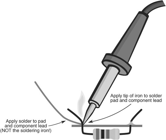
Figure 30-9 Remember to always apply the tip of the soldering tool to the work, not the solder. (Exception: You may apply the solder directly to the tool when tinning the tip. Do this periodically after wiping off the tip against a damp sponge.)
5. Wait 3 to 5 seconds, and then touch the end of the solder against the opposite side of the solder pad. The solder should begin to flow into the pad and around the component lead (Figure 30-9). Allow just enough solder to flow into the joint, then immediately remove both the solder and soldering pencil.
6. If the solder does not flow, wait a few seconds more and try again. If it’s still not flowing, the soldering pencil may not yet be hot enough. Remove the tip from the work, and wait another minute for the soldering pencil to reach proper operating temperature.
7. It takes several seconds for the solder to cool. During this time, be absolutely sure not to disturb the solder joint, or it could be ruined.
Don’t apply heat any longer than necessary. Prolonged heat can permanently ruin electronic components. A good rule of thumb is that if the soldering tool is on any one spot for more than 5 seconds, it’s too long.
Finishing Up
When soldering on printed circuit boards, you’ll need to clip off the excess leads that protrude beyond the solder joint. Use a pair of diagonal or flush cutters for this task. You don’t need (or want) to cut off any part of the solder, so don’t be too aggressive with the nippers; it’s okay if a little stubble of wire still sticks out.
Be sure to protect your eyes when cutting the lead; a bit of metal could fly off and lodge in an eye. Not fun.
Tips for Better Soldering
![]() If at all possible, you should keep the tool at a 30° to 40° angle for best results. Most tips are beveled for this purpose.
If at all possible, you should keep the tool at a 30° to 40° angle for best results. Most tips are beveled for this purpose.
![]() Apply only as much solder to the joint as is required to coat the lead and circuit board pad. A heavy-handed soldering job may lead to solder bridges, which is when one joint melds with joints around it. That can cause a short circuit.
Apply only as much solder to the joint as is required to coat the lead and circuit board pad. A heavy-handed soldering job may lead to solder bridges, which is when one joint melds with joints around it. That can cause a short circuit.
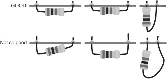
Figure 30-10 Good and not-so-good examples of soldering. When soldering components to a circuit board, be sure the parts are in fully and straight.
![]() When the joint is complete and has cooled, test it to make sure it is secure. Wiggle the component to see if the joint is solid.
When the joint is complete and has cooled, test it to make sure it is secure. Wiggle the component to see if the joint is solid.
![]() Be sure to insert the component completely though the circuit board, and check that it isn’t crooked (see Figure 30-10). Excessive component lead length can cause short circuits if they touch other exposed parts of the board.
Be sure to insert the component completely though the circuit board, and check that it isn’t crooked (see Figure 30-10). Excessive component lead length can cause short circuits if they touch other exposed parts of the board.
SOLDER TIP MAINTENANCE AND CLEANUP
As the soldering tool comes to temperature, clean off the tip by wiping it against a damp sponge. As you work, periodically repeat this step to keep the tip free of excess solder.
The tip should always be tinned, meaning it should have a very light coat of solder on it. Tinning involves cleaning off the tip with the damp sponge, then directly applying a bit of solder to the tip (this is one instance when applying the soldering tool directly to the solder is allowed). Remove any excess solder by wiping again with the damp sponge.
After soldering, let the tool cool down for at least 10 minutes before putting it away.
After many hours of use, the soldering tip will become old, pitted, and deformed. This is a good time to replace the tip. Old or damaged tips impair the transfer of heat, and that can lead to poor soldering joints. Be sure to replace the tip with one made specifically for your soldering tool. Different brands of tips are generally not interchangeable.
Using Headers and Connectors
Most robots are constructed from subsystems that may not be located on the same circuit board. So you need to connect these subsystems together using some kind of wiring system. For very simple connections, you can directly solder wires between boards and other components. But as the electronic systems of your bot get more complex, such direct connections make it harder to experiment.
The solution: Use connectors whenever possible. In this approach, you connect the various subsystems of your robot together using wires that are terminated with a connector of some type or another. The connectors attach to mating pins on each circuit board.
MAKING YOUR OWN MALE CONNECTORS
You don’t need fancy cables and cable connectors for your robots. In fact, these can add significant weight to your bot. Instead, use ordinary 20-to 26-gauge wire, terminated with single-or double-row plastic headers.
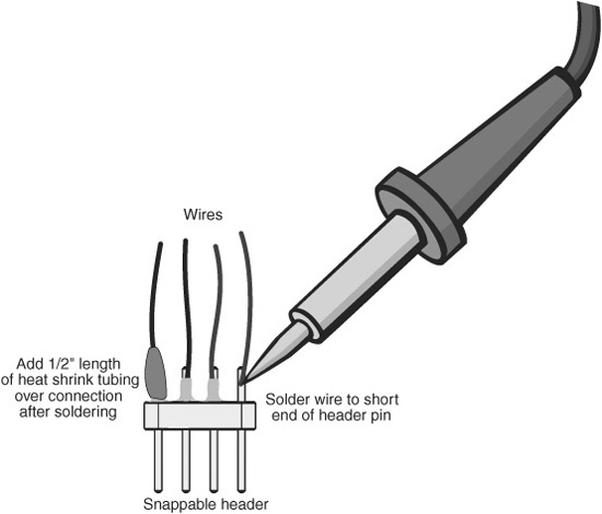
Figure 30-11 Make your own male header connectors by soldering wires to the short end of the header pins. For a professional look use heat shrink tubing over the solder joint.
You can make these yourself using breakaway header pins. You buy them in lengths of 10 or more pins, then break off as many as you need. Solder wires to the underside of the pins. Insert the top side into sockets on your circuit boards. Figure 30-11 shows how. The optional heat shrink tubing is applied by cutting a small piece of the tube and slipping it over the soldered wire. Shrink the tube using a heat gun or hair dryer set on high.
PREPARING FEMALE CONNECTORS
If you’re connecting to a circuit board that already uses male pins, you’ll need to use a female connector to hook things up. You can make these by purchasing a connector set that’s designed for the pins you’re plugging into. These vary by the number of pins and the pin spacing, so be sure to get the right set. Most pin headers use 0.100″ spacing. There are smaller and larger spacings, but these are obvious just by looking at them.
Referring to Figure 30-12 as a guide, to make a connector prepare the end of a wire by removing about 1/4″ to 3/8″ of insulation. When using stranded conductor wire, twist the strands together. Insert the end of the wire into a crimp-on connector piece. Secure the wire in the connector by crimping it; a crimping tool made for the job works best. You then insert the connector piece into the plastic shell. The connector snaps into place in the shell.

Figure 30-12 Make your own female connectors using a connector shell and crimp on sockets.
BEST CONNECTIONS
Use plastic ties to bundle the wires together. This keeps them all tidy. Or, instead of using individual lengths of insulated wire, use ribbon cable, which is made of many pieces of wire bonded together as a unit.
When making interconnecting cables, cut the wires to length so there is a modest amount of slack between subsystems. You don’t want the wire lengths so short that the components are put under stress when you connect them together. But don’t go overboard; you also don’t want, or need, gobs of excess wire.
Using Clip-on Jumpers
Another kind of cable is used when experimenting with and testing your robot electronic circuits. These are clip-on jumpers. The jumper is made with flexible insulated wire, where both ends have some kind of spring-loaded clip. You attach the clips to wires, components, or another part of the circuit to make temporary connections.
You should get at least one set of clip-on jumpers for routine testing and experimenting. Jumpers are available with three basic kinds of clip-on ends:
![]() Small alligator clamp, useful for smaller components and wires. Don’t use these to attach to an individual pin on an integrated circuit (IC). They’re too large and will cause a short.
Small alligator clamp, useful for smaller components and wires. Don’t use these to attach to an individual pin on an integrated circuit (IC). They’re too large and will cause a short.
![]() Large alligator clamp, good for motors and other, bigger components (the wiring is heavier, too).
Large alligator clamp, good for motors and other, bigger components (the wiring is heavier, too).
![]() Push-in hooks, ideal for use when connecting to the individual integrated circuit pins.
Push-in hooks, ideal for use when connecting to the individual integrated circuit pins.
All three kinds are shown in Figure 30-13.
Good Design Principles
While building circuits for your robots, observe the good design principles described in the following sections, even if the schematic diagrams you are working from don’t include them.
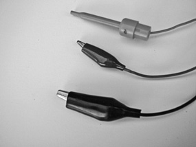
Figure 30-13 Assortment of common jumper cables: hook, small alligator, and large alligator. They come in various colors and lengths. Always use the jumpers that have fully insulated (plastic-covered) clamps. They help prevent short circuits.
FYI
Some of these concepts assume you already know what a resistor and capacitor are. If you don’t, then no worries; these topics are covered in Chapter 31. This is just a review of ways to improve the functionality of your robot circuits.
USE PULL-UP/PULL-DOWN RESISTORS
When something is unplugged in your robot, the input voltage might waver back and forth. This can influence the proper functioning of your robot. Use pull-up or pull-down resistors on any circuit inputs where this could be a problem. A common value is 10 kΩ; 10,000 ohms). In this way, the input always has a “default” state, even if nothing is connected to it.
A pull-up resistor is connected between the input and the + (positive) power supply of the circuit; a pull-down resistor is connected between the input and − (negative or ground), as shown in Figure 30-14.
TIE UNUSED INPUTS LOW
Unless the instructions for a component say otherwise, tie unused inputs to ground to keep them from “floating”—floating means an indeterminate voltage state. A floating input can cause the circuit to go into oscillation, rendering it practically unusable.
USE DECOUPLING CAPACITORS
Some electronic components, especially fast-acting logic chips and the venerable LM555 timer IC, generate a lot of electrical noise that can spread through the power supply connections. You can reduce or eliminate this noise by using decoupling (also called bypass) capacitors, like that in Figure 30-15.
These aren’t specific types of capacitors; rather, “decoupling” refers to the job they perform. The value of the capacitor isn’t supercritical. I like to use 1 µFto 10 µF (1 to 10 microfarad) tantalum electrolytic capacitors positioned between the positive and ground terminals of the noisy component. Some designers like to use a decoupling capacitor on every integrated circuit, while others place them beside every third or fourth IC on the board.

Figure 30-14 Concept of the pull-down and pull-up resistor. A common value of the resistor is 10 kΩ.
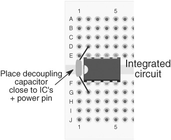
Figure 30-15 Concept of the decoupling capacitor: It’s a capacitor placed near the power pins of an integrated circuit or other component, which acts to “decouple” (separate out) any noise that may be in the power supply.

Figure 30-16 A ground loop is when there is more than one path for the ground connection. Ground loops can cause erratic behavior in circuits. Always connect the ground leads of components to one central point.
It’s also a good idea to put decoupling capacitors between the positive and ground connections of any circuit at the point of entry of the power supply wires. Many engineering texts suggest the use of 1 µF to 100 µF tantalum capacitors for this job. Remember that tantalum capacitors are polarized—they have a + and a − side. Be sure to properly orient the component in the circuit, or the capacitor (and maybe some other parts) will be ruined.
KEEP LEAD LENGTHS SHORT
Long wire leads on components can introduce electrical noise in other parts of a circuit. The long leads also act as a virtual antenna, picking up stray signals from the circuit, from overhead lighting, and even from your own body. When designing and building circuits, try to keep lead lengths as short as you can for everything. When soldering, this means soldering the components close to the board and clipping off any excess lead length.
AVOID GROUND LOOPS
A ground loop is when the ground wire of a circuit comes back and meets itself. The positive and ground connections of your circuits should always have “dead ends” to them. Ground loops can cause erratic behavior and excessive noise in the circuit. See Figure 30-16 for a visual depiction of a nasty ground loop that almost guarantees problems.
RoHS Demystified
![]()
Ever wondered about that “RoHS” thing that you see with many other electronic parts these days? RoHS standards for Restriction of Hazardous Substances directive, a worldwide effort to reduce the amount of toxic materials in commercially produced electronic devices. These materials—which include lead, mercury, and cadmium—present significant health hazards as tons of discarded electronic circuit boards are dumped into landfills. Yecch!, as Alfred E. Neuman would say.
In following various international laws, many sellers of electronic components and completed circuits list whether a product is RoHS compliant. In the case of electronic components, RoHS compliance typically indicates that the use of lead is either reduced or eliminated. Not being in compliance does not mean the product is inferior, just that its manufacture does not yet meet the very strict RoHS standards.