
Chapter 43
Proximity and Distance Sensing
You’ve spent hundreds of hours designing and building your latest robot creation. It’s filled with complex little doodads and precision instrumentation. You bring it into your living room, fire it up, and step back. Promptly, the beautiful new robot smashes into the fireplace and scatters itself over the living room rug. You remembered things like motor speed controls, electronic eyes and ears, even a synthetic voice, but you forgot to provide your robot with the ability to look before it leaps.
Proximity and distance sensing is all about collision avoidance. These systems take many forms, and the most basic are easy to build and use. In this chapter, we present a number of passive and active detection systems you can use in your robots. You’ll read about several affordable and easily reproducible sensors you can use for collision avoidance.
![]()
Source code for all software examples may be found at the RBB Online Support site. See Appendix A, “RBB Online Support,” for more details. To save page space, the lengthier programs are not printed here. The support site also offers source code with added comments, parts lists (with sources) for projects, updates, extended construction plans, and more examples you can try!
Design Overview
For a robot to be self-sufficient in the human world, it must be able to determine its environment. It does this by sensing objects, obstacles, and terrain around it. This can include you, the cat, an old sock, the wall, the little hump on the ground between the carpet and the kitchen floor, and a million other things.
Robots sense objects using either contact or noncontact means. With contact sensing, the robot detects a collision after it’s happened. With noncontact sensing, the robot is able to avoid a collision before it happens. Collision detection and collision avoidance are two similar but separate aspects of robot design.
![]() In Chapter 42, “Adding the Sense of Touch,” you learned about techniques in collision detection, which concerns what happens when the robot has already gone too far and contact has been made with whatever foreign object was unlucky enough to be in the machine’s path.
In Chapter 42, “Adding the Sense of Touch,” you learned about techniques in collision detection, which concerns what happens when the robot has already gone too far and contact has been made with whatever foreign object was unlucky enough to be in the machine’s path.
![]() With collision avoidance, the subject of this chapter, the robot uses noncontact techniques to determine the proximity and/or distance of objects around it. It then avoids any objects it detects.
With collision avoidance, the subject of this chapter, the robot uses noncontact techniques to determine the proximity and/or distance of objects around it. It then avoids any objects it detects.
Collision avoidance can be further broken down into two subtypes: near-object detection and far-object detection.
FYI
Robot builders commonly use certain object detection methods to navigate a robot from one spot to the next. Many of these techniques are introduced here because they are relevant to object detection, but for navigation they are developed more fully in Chapter 45, “Navigating Your Robot.”
NEAR-OBJECT DETECTION
Near-object detection does just what its name implies: it senses objects that are close by, from perhaps just a breath away to as much as 8 or 10 feet. These are objects that a robot can consider to be in its immediate environment, objects it may have to deal with, and soon. These objects may be people, animals, furniture, or other robots. By detecting them, your robot can take appropriate action, which is defined by the program you give it.
There are two ways to effect near-object detection: proximity and distance (see Figure 43-1):
![]() Proximity sensors care only that some object is within a zone of relevance. That is, if an object is near enough in the physical scene the robot is looking at, the sensor detects it and triggers the appropriate circuit in the robot. Objects beyond the proximal range of a sensor are effectively ignored because they cannot be detected.
Proximity sensors care only that some object is within a zone of relevance. That is, if an object is near enough in the physical scene the robot is looking at, the sensor detects it and triggers the appropriate circuit in the robot. Objects beyond the proximal range of a sensor are effectively ignored because they cannot be detected.
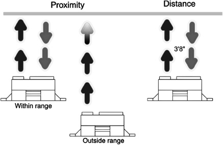
Figure 43-1 Proximity versus distance detection. Proximity provides a go/no-go result, while distance gives the actual closeness of an object.
![]() Distance measurement sensors determine the distance between the sensor and whatever object is within range. Distance measurement techniques vary; almost all have notable minimum and maximum ranges. Few yield accurate data if an object is smack-dab next to the robot. Likewise, objects just outside range can yield inaccurate results. Large objects far away may appear closer than they really are; very close small objects may appear abnormally larger.
Distance measurement sensors determine the distance between the sensor and whatever object is within range. Distance measurement techniques vary; almost all have notable minimum and maximum ranges. Few yield accurate data if an object is smack-dab next to the robot. Likewise, objects just outside range can yield inaccurate results. Large objects far away may appear closer than they really are; very close small objects may appear abnormally larger.
Both detection schemes use similar technologies. The most common proximity detection schemes use infrared light or ultrasonic sound. If enough light (or sound) is reflected off the object, and received back to the robot, then an object is within proximity.
FAR-OBJECT DETECTION
Far-object detection focuses on objects that are outside the robot’s primary area of interest, but still within a detection range. A wall 50 feet away is not of critical importance to a robot, but a wall 1 foot away is very important.
The difference between near- and far-object detection is relative. As the designer, builder, and master of your robot, you get to decide the threshold between near and far objects. Perhaps your robot is small and travels fairly slowly. In that case, far objects are those 4 to 5 feet away; anything closer is considered “near.” With such a robot, you can employ ordinary sonar distance systems for far-object detection, including area mapping.
SENSOR DEPTH AND BREADTH
Sensors have depth and breadth limitations:
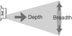
Depth is the maximum distance an object can be from the robot and still be detected by the sensor. Except for some ultrasonic sensors, most proximity and distance-measuring detectors for amateur robotics are limited to less than about 6 feet.
Breadth is the height and width of the sensor detection area at any given distance. Some sensors have a very wide “beam” width, covering a large area at a time. Others are much more narrow and focused. There’s a place for both.
Sensors that use light can use lenses to focus the beam into a smaller spot. In this way the sensor detects only what’s directly in front of it. Ultrasonic sensors use various means to control their beam pattern. Some are very narrow, while others are wide. Makers of ultrasonic sensors for use in robotics provide a picture of the beam spread, so you can match the detector to your planned use.
Simple Infrared Light Proximity Sensor
Avoiding a collision is better than detecting it once it has happened. Short of building some elaborate radar distance measurement system, the ways for providing proximity detection to avoid collisions fall into two categories: light and sound. Let’s start with a simple sensor using light.

Figure 43-2 This simple proximity detector works by sensing infrared light reflected off an object. The output is a voltage proportional to the brightness of light falling on the phototransistor.
Light may always travel in a straight line, but it bounces off nearly everything. You can use this to your advantage to build an infrared collision detection system. You can mount several infrared “bumper” sensors around the periphery of your robot. They can be linked together to tell the robot that “something is out there,” or they can provide specific details about the outside environment to a computer or control circuit.
A basic (and very simplistic) infrared detector is shown in Figure 43-2, along with a suitable interface circuit. It uses an infrared LED and infrared phototransistor. The output of the transistor can be connected to any number of control circuits, including a microcontroller or voltage comparator. Experiment with the value of the resistor above the phototransistor. Lower resistance values decrease sensitivity; higher values increase sensitivity.
ADJUSTING SENSITIVITY
Sensitivity of the detector can be adjusted by changing the value of the resistor above the phototransistor; reduce the value to increase sensitivity. An increase in sensitivity means that the robot will be able to detect objects farther way. A decrease in sensitivity means that the robot must be fairly close to the object before it is detected.

Objects reflect light in different ways. You’ll probably want to adjust the sensitivity so the robot behaves itself best in a room with white walls. But that sensitivity may not be as great when the robot comes to a dark brown couch or the coal gray suit of your boss.
The infrared phototransistor should be baffled—blocked—from both ambient room light as well as direct light from the LED. Try placing a short piece of black heat-shrink tubing (unshrunk) over either or both the infrared LED or the phototransistor. The positioning of the LED and phototransistor is very important, and you must take care to ensure that the two are properly aligned.
You may wish to mount the LED-phototransistor pair in a small block of wood. Drill holes for the LED and phototransistor. Or, if you prefer, you can buy the detector pair already made up and installed on a circuit board. The one in Figure 43-3 is made by Parallax (see Appendix B, “Internet Parts Sources”).
USING INFRARED DETECTORS ON GRIPPERS
You can mount an infrared detector pair on the tips of the fingers or pinchers of a robot grip-per, like that in Figure 43-4. This arrangement is useful for telling the robot that there’s something nearby to grasp. In a typical gripper design, two or more LEDs and phototransistors are placed along the length of the grippers or fingers to provide more positive control. Alternatively, you may wish to detect when an object is closest to the palm of the gripper. You’d mount the LED and phototransistor accordingly.

Figure 43-3 Integrated IR emitter and detector modules provide a quick way to add light sensors to your robot. Standard.100″ connector pins provide easy hookup. (Photo courtesy Parallax Inc.)
Modulated Infrared Proximity Detector
The basic infrared emitter/detector system has a distinct disadvantage—namely, the phototransistor is susceptible to ambient lighting. This kind of sensor tends to work best in a darkened room, where there is little chance of light from a lamp or the sun striking the phototransistor.
Another method is to use a simple technique that’s grown much in popularity over the past years: the modulated infrared proximity detector, or IRPD. These also use infrared emitters and detectors. But to avoid the problems of ambient light spoilage, the system uses a beam of rapidly pulsating, or modulated, light. The detector looks only for light that is modulated at the proper frequency, that is flashing on and off at the correct speed. Everything else, it ignores.
Sounds complicated, but in practice it’s fairly easy to do, thanks to the wide availability of remote control receiving modules, which form the heart of the IRPD. These are the same modules used in TVs, DVD players, and other devices to receive commands from an infrared remote control.
THE BASIC IRPD CIRCUIT
Figure 43-5 shows a typical IRPD circuit. It has two halves, working in concert:

Figure 43-4 Light sensors can be used for more than avoiding contact with obstacles. They can also be used within the robot itself as position or grip indicators. This IR LED and detector can sense when the fingers of a gripper are very close together.

Figure 43-5 Modulated light overcomes many of the problems of using simpler forms of infrared detectors. The sensor is less likely to be influenced by ambient light. This circuit comprises a 555 timer IC providing a steady stream of pulses, that are then picked up by an infrared receiver/demodulator that is turned to the same pulse rate.
![]() A timing circuit, in this case a low-power LM555 IC, pulses an infrared LED to about 38 kHz (38,000 cycles per second).
A timing circuit, in this case a low-power LM555 IC, pulses an infrared LED to about 38 kHz (38,000 cycles per second).
![]() The infrared receiving module is tuned to the same 38-kHz frequency. If there’s no 38-kHz light beam around, the output of the module stays HIGH. The moment it detects pulses of 38-kHz light, the output of module goes LOW.
The infrared receiving module is tuned to the same 38-kHz frequency. If there’s no 38-kHz light beam around, the output of the module stays HIGH. The moment it detects pulses of 38-kHz light, the output of module goes LOW.
Many IRPDs use two LEDs, which are pulsed alternately. By checking which LED is pulsing at the time a signal is received through the module, the robot can detect if the object is to the left, to the right, or straight ahead. We’ll look at this technique in a bit.
The frequency doesn’t have to be exactly 38 kHz, though the closer it is to this value, the more sensitive the detector will be. There is some latitude in the accepted frequency range of the infrared receiver. With the components shown, and assuming exact values, the frequency of the timer is 37.8 kHz, which is certainly close enough.
In my prototype the measured frequency was actually 39.2 kHz, and the circuit still worked. The variance in measured frequency is due to normal component tolerance. I used resistors with 5 percent tolerance, and the .001 μF monolithic capacitor was rated at 10 percent.
If you wish to experiment with the frequency setting, replace the 15 kΩ resistor with a combination 12 kΩ fixed resistor and a 5 kΩ potentiometer. Wire the pot so that one of its legs is connected to the 8.2 kΩ resistor, and the wiper is connected to pin 6 of the LM555 IC. From one extreme of the pot to the other, the frequency range should span from about 34.2 kHz to 44.8 kHz.
Detection range can be from inches to well over a foot, depending on the exact frequency of the timer and the power output of the infrared LED. You probably don’t want a supersensitive detector. Alter the value of the 470 Ω dropping resistor connected to the infrared LED. Higher values weaken the strength of the light, which reduces detection range; lower values increases range. Don’t go below about 200 Ω, or you risk smoking the LED by passing it too much current.
Point the LED and emitter away from your solderless breadboard or circuit board. Otherwise you’ll get false readings due to reflected light.
Increase directionality (and decrease false readings) by inserting a 3/4″ length of black heat-shrink tubing over the emitter LED. The longer the tube, the more discriminating the sensor will be.
Add a baffle between the IR emitter LED and the receiver module. Try a small piece of that black conductive foam they use to hold static-sensitive ICs and other components.
Try different infrared LEDs to experiment with range. Small IR emitters with 2- to 10-mW output are useful for “close in” detection of just a few inches. Check the datasheet for the LED to determine its power output.
Keep lead lengths trimmed (especially the capacitors) or else you could get erratic results. Once you get the circuit tested and working, transfer it from your solderless breadboard to a soldered board.
“Detune” the frequency to alter the effective range of the detector. Try a frequency that’s off by 1 to 4 kHz from 38 kHz to make your detector a little less sensitive.
CONNECTING TO A MICROCONTROLLER
Interfacing the IRPD to a microcontroller is straightforward. You can generate the pulses for the infrared detector using a separate circuit, such as an LM555 timer as shown in Figure 43-5, do it in your microcontroller, or use a separate microcontroller
Using an LM555 timer IC or a separate microcontroller to generate the modulation allows your main controller more freedom to do other, more important things.
LM555-Based Timer
Refer again to Figure 43-5. The LM555 timer is left free-running, generating a steady stream of (approximately) 38-kHz pulses. If the detector module is close enough to receive the pulses, its output goes LOW, which is registered in software running in the microcontroller.
The sketch irpd.pde for the Arduino demonstrates reading the IR sensor and lighting the built-in LED whenever the receiver detects a stream of 38-kHz pulses. The LED stays lit for a quarter of a second and turns back off if the pulse stream is no longer detected.
In my tests, using the component values shown in Figure 43-5 and a high-output IR LED rated at 16 mW (RadioShack, catalog #276-143), I got a detection distance of well over a foot.

irpd.pde

Auxiliary Microcontroller
Most infrared modules prefer that that modulation not be continuous. What it likes best is that the pulses turn on and off once every millisecond or so. This improves operating range. The on/off sequence works with the detector’s internal autogain circuitry; it’s how the detector adjusts to the ambient light of the room.
With the low cost of many microcontrollers, you can implement a full timing circuit that mimics the LM555 and also toggles the modulation on for 50 milliseconds and off for 20 milliseconds. The controller need not have lots of pins, features, or memory, as producing timed signals is a simple task. One good candidate for this task is the PICAXE 08M, costing just a few dollars. It’s both easy to program and simple to interface with other electronics.
Figure 43-6 shows the basic hookup. The PICAXE 08M is connected to an infrared emitter by way of a current-limiting resistor. Program code running in the PICAXE controls the modulation frequency and the on/off cycling. The sample program is shown in irpd-pic axe-simple.bas.
This example shows the PICAXE 08M generating the light modulation, with some other microcontroller or other circuit solution to detect proximity. With just a little bit of extra code you can develop a self-contained IRPD system where the PICAXE provides the modulation and monitors the detector. See the next section, “Enhanced IRPD Circuit.”
irpd-picaxe-simple.bas
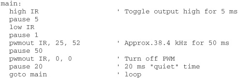
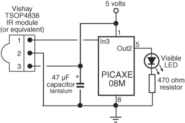
Figure 43-6 A microcontroller may be used to generate the modulated light pulses for use with an infrared receiver/demodulator.

Figure 43-7 Enhanced version of the light modulator based on the PICAXE 08M microcontroller. This one alternatively pulses two infrared LEDs; the receiver/demodulator is placed between the LEDs. Another microcontroller (your design) checks to see which LED was active if/when the receiver was triggered.
ENHANCED IRPD CIRCUIT
As noted, by using a pair of infrared emitters, each producing a short burst of modulated light, your robot can determine whether an object is to the right, to the left, or straight ahead. While you can produce such a sequence using a couple of LM555 timers (or its LM556 dual-timer cousin), it’s easier and perhaps even more cost effective to use a microcontroller. Once again, a good job for the PICAXE 08M.
The wiring diagram for the enhanced IRPD is shown in Figure 43-7. Two infrared emitters are used (you still use one detector positioned between them). The distance between the emitters and the detector is variable; a few inches is typical, but you can try 6″ to 8″, and angle the front of the emitters slightly inward to help pinpoint the infrared light so that the emitter adequately sees it. Feel free to play!
By placing the detector slightly ahead of the emitters, you can reduce problems of “crosstalk,” where light from the emitters goes straight into the infrared detector. You can also try adding a heavy black paper or plastic baffle along the sides of the emitter, or outfitting the front of it with a small length of black heat-shrink tubing to keep stray light from the emitters.
Program code for the enhanced IRPD is found in irpd-picaxe-enhanced.bas. Two infrared LED emitters are connected to pwm2 (physical pin 5 of the PICAXE 08M) through one current-limiting resistor—this is okay because only one LED will ever be turned on at any time. Each LED is then toggled on and off via program code: the program statement low turns it on, and high turns it off.
irpd-picaxe-enhanced.bas

The visible LED connected to pin 0 is a visual indicator that shows which side—if any—is currently triggering the sensor.
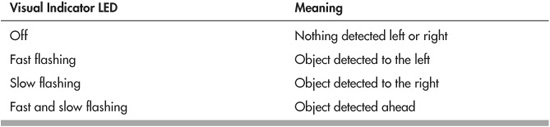
The LED flashing code is for your own amusement. In a working robot you’d probably want to connect the output of the PICAXE-as-proximity-detector to the main controller, and indicate left/right/center by some other means. One simple way might be:
![]() Output LOW: no detection
Output LOW: no detection
![]() Output HIGH: left detection
Output HIGH: left detection
![]() Output rapid flash: right detection
Output rapid flash: right detection
Or you can use a serial communications link to another controller. The PICAXE 08M supports several serial commands, including sertxd, which just happens to use pin0, the same pin the LED is connected to (so you don’t have to do any rewiring). Set up a link to your other processor and send simple codes to indicate proximity detection. Purely as a demonstration, the following sends explanatory text, plus ASCII codes to insert a new line.
   ToggleL:

     ′ activate left IR LED

     if pin3=0 then

       sertxd(″Something is to the left″, 13, 10)

     end if

     ′ deactivate left IR LED …
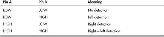
Instead of text, you can use code values that only you and your robot’s microcontrollers know—maybe 0 for no detection, 1 for left, 2 for right, and 3 for both.
If you’re using a PICAXE chip with additional I/O to spare, you can use two pins to denote four possible states. In the following table the pins are marked Pin A and Pin B; the actual pins are the two outputs you have selected to use for your interface.
Infrared Distance Measurement
Not only can infrared light be used to detect if something is nearby, it can measure the distance between your bot and some object. Infrared distance measurement detectors use the displacement of reflected light across a linear sensor (see Figure 43-8).
Here’s how the technique works: A beam of infrared light from the sensor illuminates some object. The beam reflects off the object and bounces back into the sensor. The reflected beam is focused onto what’s known as a position-sensitive device, or PSD. The PSD has a surface whose resistance changes depending on where light strikes it. As the distance between sensor and object changes, so does the linear position of the light falling on the PSD. Circuitry in the sensor monitors the resistance of the PSD element and calculates the distance based on this resistance.

Figure 43-8 The inner workings of the Sharp infrared distance and proximity sensors. Light from an emitter bounces off an object and reenters the sensor at some angle, as shown. The reflected beam strikes against a position-sensitive detector. This sensor detects when light falling on it is off center.
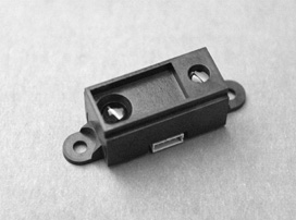
Figure 43-9 Example Sharp IR sensor. This variation of the sensor has convenient screw eyelets for easy mounting.

Figure 43-10 The important parts of a Sharp IR sensor. Note the three-pin JST connector. This is smaller than the typical.100″ connector you may be used to, and it requires a special cable.
Nearly all of the infrared distance-measuring modules you’ll find are made by Sharp. Figure 43-9 shows a typical Sharp infrared proximity sensor, and Figure 43-10 an outline view of the important parts on it. All share better-than-average immunity to ambient light levels, so you can use them under a variety of lighting conditions (except very, very bright light outdoors).
The sensors use a modulated—as opposed to a continuous—infrared beam that helps reject false triggering. It also makes the system accurate even if the detected object absorbs or scatters infrared light, such as heavy curtains or dark-colored fabrics.
Most of the Sharp IR modules use a miniature JST-type three-prong connector. At a distance it looks like the typical 0.100″ connector, but it’s smaller. When buying an infrared module, be sure to get the right connector with it.
The circuitry of the sensor can provide either a digital or an analog output. Both are routinely used in robotics, so we’ll cover them both.
EXPLORING THE DIFFERENT TYPES OF SENSORS
Infrared distance sensors aren’t made with robotics in mind—it’s just that they’re perfect for the job. Rather, they are intended for use in industrial control. Because of this, there are several models to choose from, each with a unique set of features.
![]() Working distance is the effective minimum and maximum distance of the sensor. “Effective” means the distance at which you get accurate detection. Distances are almost always noted in centimeters. The minimum working distance of the most popular Sharp sensor model is 10 cm, or roughly 4″. Maximum working distance is 80 cm (31.5″). Outside this range, the sensor may still pick up an object, but measurement accuracy may be affected.
Working distance is the effective minimum and maximum distance of the sensor. “Effective” means the distance at which you get accurate detection. Distances are almost always noted in centimeters. The minimum working distance of the most popular Sharp sensor model is 10 cm, or roughly 4″. Maximum working distance is 80 cm (31.5″). Outside this range, the sensor may still pick up an object, but measurement accuracy may be affected.
![]() Beam width (or spread) relates to how much of an area the sensor “sees.” Most IR modules tend to have a fairly narrow beam width, often just 5° to 10°. This means that the object needs to be almost straight on to the sensor to be detected. Some versions are designed to have a wider field, and some a narrow field of view. Pick the one you want based on your application.
Beam width (or spread) relates to how much of an area the sensor “sees.” Most IR modules tend to have a fairly narrow beam width, often just 5° to 10°. This means that the object needs to be almost straight on to the sensor to be detected. Some versions are designed to have a wider field, and some a narrow field of view. Pick the one you want based on your application.
![]() Digital go/no-go output sensors are the simplest to use. Their output is either LOW or HIGH, depending on whether an object is within a set proximity range. These are called distance judgment sensors, because they merely judge that the distance is within a certain range.
Digital go/no-go output sensors are the simplest to use. Their output is either LOW or HIGH, depending on whether an object is within a set proximity range. These are called distance judgment sensors, because they merely judge that the distance is within a certain range.
![]() Analog measurement output provides a varying voltage representing distance. The distance to voltage is not a linear (straight path) relationship, which makes very accurate readings a challenge. These are called distance measurement sensors, as they tell you the distance between the module and the object.
Analog measurement output provides a varying voltage representing distance. The distance to voltage is not a linear (straight path) relationship, which makes very accurate readings a challenge. These are called distance measurement sensors, as they tell you the distance between the module and the object.
I’ll talk about two of the more popular Sharp IR modules here, but recognize that there are others available from your favorite online robotics specialty retailer (model numbers can come and go, so always look for the newest stuff). They work pretty much along the same lines, except they have different working distances and beam widths.
![]() GP2D15—LOW/HIGH digital output indicates whether an object is within 24 cm, or about 9.5″. It’s very simple to use
GP2D15—LOW/HIGH digital output indicates whether an object is within 24 cm, or about 9.5″. It’s very simple to use
![]() GP2D12—Analog output indicates range as a voltage level.
GP2D12—Analog output indicates range as a voltage level.
Sharp’s datasheets for their infrared modules have been known to contain errors, such as saying that a module has a digital output when it’s really analog. These errors eventually get corrected in updates. Be sure to get the latest version of the datasheets, ideally from the Sharp Web site itself.
BASIC ELECTRICAL HOOKUP
Many of the Sharp IR modules follow a standard connection scheme, shown in Figure 43-11.
![]() Pin 1—Signal output. This terminal may provide a digital or an analog signal, as described in the previous section.
Pin 1—Signal output. This terminal may provide a digital or an analog signal, as described in the previous section.
![]() Pin 2—Power supply ground.
Pin 2—Power supply ground.
![]() Pin 3—Power supply voltage, which is 4.5 to 5.5 volts (most units).
Pin 3—Power supply voltage, which is 4.5 to 5.5 volts (most units).
Several sources, such as Lynxmotion, offer adapter cables that go from the specialty JST connector to a standard 0.100″ connector. On many of these adapter cables the pin order is altered, so be mindful of this. Follow the color coding of the wires to keep track of what goes where.
Why do they flip the pins? They’re following good practice by placing the +V connection in the center. That way, if the cable is plugged in backward, there is less chance of wrecking the sensor. It also standardizes on the same connection scheme used by radio control servo motors.
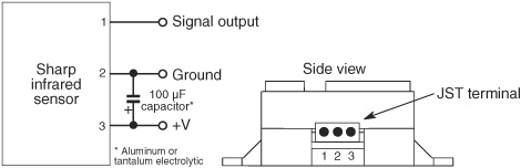
Figure 43-11 Typical connection diagram for the Sharp IR sensors. Not all follow this hookup, but most do. The output may be a digital (on/off) signal or an analog voltage.
Note that some earlier versions of the Sharp sensors, such as the GP2D02, used a different pin configuration. Several other compact models, not covered here, use a six-pin connection and require external components for proper operation.
USING THE GP2D15 INFRARED DISTANCE JUDGMENT SENSOR
The GP2D15 is a “distance judgment” sensor rather than a ranging sensor. It has a 1-bit output that is either HIGH or LOW depending on whether an object has been detected within a threshold range, which is factory-set at 25 cm. This simple connection makes the GP2D15 the easiest to use, as long as you only need to know there’s an object closer than 9-1/2″. Use it as you would a mechanical bumper switch.
The GP2D15 replaces an earlier version, the GP2D05, where you could adjust the threshold range. I’ve seen some instructions on the Web for hacking the range of the GP2D15, but unless you’re real good at it, I’d advise against this. It’s easy to ruin one of these modules by taking it apart.
You’re better off using an analog output sensor, like the GP2D12 (see next section), and connecting it to an LM339 comparator, like that shown in Figure 43-12. Don’t forget the pull-up resistor on the output of the comparator. Dialing the potentiometer alters the reference voltage to the comparator.
USING THE GP2D12 ANALOG OUTPUT INFRARED RANGING SENSOR
The GP2D12 analog output infrared sensor is one of the more commonly used of the Sharp units (along with its close sibling, the GP2D120, which has different optics for a shorter range). Its output is an analog voltage that follows the distance between module and object. Starting from the minimum working distance, the voltage goes down as the distance to the object increases; the lowest voltage is present at the maximum working distance, and beyond.
The voltage span of the GP2D12 is approximately 0.4 to 2.4 volts; this can vary minutely from unit to unit. The ideal way to measure this voltage is with a microcontroller equipped with at least one ADC input. A sample program using the Arduino is shown in gp2d12.pde.
Remember that the voltage output of the GP2D12 is not linear (see Figure 43-13), which means that you can’t expect a 1:1 ratio between the value you get and the distance separating the sensor and the detected object. While you could write a math function that attempts to linearize the curved analog response of the GP2D12, many people use a short lookup table or switch statement that correlates voltage to approximate distance. Conduct tests with objects placed at set distances from the sensor (use a tape measure for accuracy), and use those as benchmarks.
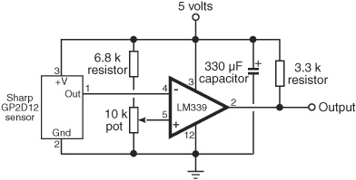
Figure 43-12 How to use an analog output sensor with a voltage comparator. The comparator triggers when the voltage from the sensor reaches a certain point, as set by the 10 kΩ potentiometer.
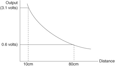
Figure 43-13 The analog voltage output of the Sharp IR sensors is not linear.
The accuracy of the readings will depend greatly on the width of the target. You may wish to experiment by placing the sensor in front of a smooth, white wall. Vary the distance between wall and sensor, and note your results.
Personally, I think it’s better to use an ultrasonic sensor when accurate distance measurement is needed, and use IR sensors for ballpark approximations—instead of worrying about exact fractions of an inch, you’re more interested in knowing whether an object is far, near, or really close.
Note that when an object is very close—less than the minimum detection range—the value returned by the sensor is meaningless. Depending on the exact sensor you use, it’ll show the same value as no detection at all. So be sure to back up an IR sensor with, at the very least, a mechanical contact switch to detect physical collision.
gp2d12.pde

SHARP IR MODULE GOOD CODING PRACTICE
Over the years, robot experimenters have discovered many useful tips and tidbits about how to best use the Sharp infrared distance measurement and distance judgment sensors. Here are several of the most important issues to keep in mind:
![]() The Sharp modules tend to draw a lot of current when operating—up to 50 mA, depending on model and the instantaneous measured distance. Keep this in mind when planning the power and battery requirements for your robot.
The Sharp modules tend to draw a lot of current when operating—up to 50 mA, depending on model and the instantaneous measured distance. Keep this in mind when planning the power and battery requirements for your robot.
![]() Though not an absolute requirement, adding a 100 μF bypass capacitor between +V and ground of the sensor helps to reduce errant readings due to induced spikes in the power supply. You may also want to add a secondary .1 μF monolithic capacitor in the same way.
Though not an absolute requirement, adding a 100 μF bypass capacitor between +V and ground of the sensor helps to reduce errant readings due to induced spikes in the power supply. You may also want to add a secondary .1 μF monolithic capacitor in the same way.
![]() After turning on a module, wait at least 100 ms (milliseconds) before taking a reading. This allows the device to settle; otherwise, the reading may be inaccurate.
After turning on a module, wait at least 100 ms (milliseconds) before taking a reading. This allows the device to settle; otherwise, the reading may be inaccurate.
![]() For greater accuracy, take several successive readings from the sensor, at no less than 50-ms intervals, and average them out.
For greater accuracy, take several successive readings from the sensor, at no less than 50-ms intervals, and average them out.
![]() In addition to averaging, you may wish to disregard any readings within a group that are wildly different from the rest. For example, if you get readings of 100, 105, 345, 97, and 101, all within 55 ms of one another, you can be fairly sure the 345 result is spurious and should not be considered.
In addition to averaging, you may wish to disregard any readings within a group that are wildly different from the rest. For example, if you get readings of 100, 105, 345, 97, and 101, all within 55 ms of one another, you can be fairly sure the 345 result is spurious and should not be considered.
![]() Accuracy is somewhat diminished when using an infrared sensor on a fast-moving robot, or when attached to a rotating sensor turret. Movement affects the reading. During travel or motion, you can use the measurements for general proximity detection, but you may wish to slow down or stop the robot (or turret) to get a more accurate distance reading.
Accuracy is somewhat diminished when using an infrared sensor on a fast-moving robot, or when attached to a rotating sensor turret. Movement affects the reading. During travel or motion, you can use the measurements for general proximity detection, but you may wish to slow down or stop the robot (or turret) to get a more accurate distance reading.
![]() The width of the infrared beam increases with distance. Use this to your advantage when placing multiple sensors on your robot. To maximize beam coverage of two sensors, point them so they cross. To minimize beam coverage (make the sensors more selective), point them away from one another.
The width of the infrared beam increases with distance. Use this to your advantage when placing multiple sensors on your robot. To maximize beam coverage of two sensors, point them so they cross. To minimize beam coverage (make the sensors more selective), point them away from one another.
On the Web: Passive Infrared Detection
Passive infrared sensors detect the proximity of humans and animals. These systems, popular in both indoor and outdoor security systems, work by detecting the change in infrared thermal heat patterns in front of a sensor. This sensor uses a pair of pyroelectric elements that react to changes in temperature. Instantaneous differences in the output of the two elements are detected as movement, especially movement by a heat-bearing object, such as a human.
Check out more about passive infrared detection on the RBB Online Support site (see Appendix A), where you’ll find several projects using pyroelectric sensors to detect movement and objects.
Ultrasonic Distance Measurement
A police radar system works by sending out a high-frequency radio beam that is reflected off nearby objects—maybe your car as you are speeding down the road. The difference between the time the transmit pulse is sent and when the echo is received denotes distance.
Radar systems are complex and expensive, and most require certification by a government authority, such as the Federal Communications Commission for devices used in the United States. Fortunately, there’s another approach you can use with robots: high-frequency sound.
Ultrasonic distance measurement—also called ultrasonic ranging—is now an old science. Polaroid used it for years as an automatic focusing aid on their instant cameras. To measure distance, a short burst of ultrasonic sound is sent out through a transducer; in this case, the transducer is a specially built ultrasonic speaker. The sound bounces off an object, and the echo is received by another transducer (this one a specially built ultrasonic microphone). A circuit then computes the time interval between the transmit pulse and the echo and comes up with distance.

Figure 43-14 Ultrasonic distance sensor, using one transducer (both sends and receives sound). (Photo courtesy Maxbotics Inc.)
(Note that some ultrasonic distance measurement sensors use one transducer for both send and receive. The one transducer is engineered as both a high-frequency speaker and a microphone.)
Not long ago, if you wanted to use an ultrasonic ranger in your robot you had to either build one yourself out of separate parts, hack an old Polaroid camera, or purchase a rather expensive ultrasonic distance-measuring experimenter’s kit. These days, complete and ready-to-go ultrasonic distance-measuring sensors, like the one in Figure 43-14, are commonly available from a variety of sources. Depending on features, prices start at about $25 to $30. These ready-made modules are the ones we’re learning about in this chapter.
FACTS AND FIGURES
First, some statistics. At sea level, sound travels at a speed of about 1130 feet per second (about 344 meters per second) or 13,560 inches per second. This time varies depending on atmospheric conditions, including air pressure (which varies by altitude), temperature, and humidity.
The time it takes for the echo to be received is in microseconds if the object is within a few inches or even a few feet of the robot. The overall time between transmit pulse and echo is divided by two to compensate for the round-trip travel time between the robot and the object.
Given a travel time of 13,560 inches per second for sound, it takes 73.7 μs (microseconds, or 0.0000737 seconds) for sound to travel 1 inch. If an object is 10 inches away from the ultrasonic sensor, it takes 737 μs to travel there, plus an additional 737 μs to travel back, for a total time of 1474 μs. The formula is:
(1474 / 2) / 73.7 = 10
First, divide the total transit time by 2, then divide by 73.7 (use 74 to avoid floating-point math), the time it takes sound to travel 1 inch at sea level.
USING AN ULTRASONIC DISTANCE SENSOR
Ultrasonic distance sensors come in several varieties. The least expensive require you to do all the calculation math yourself, though as the previous section showed, it’s not that difficult.
More advanced (and more expensive) sensors perform the math calculations themselves and provide you with either a digital or an analog output. All you have to do is tell the sensor you want a “ping,” and it sends out a brief pulse of ultrasonic sound to see if there’s anything nearby.
An advantage of using sound is that, unlike infrared sensors, it’s not sensitive to objects of different color and light-reflective properties. Still, some materials reflect sound better than others; some may even absorb sound completely.
For this reason, it’s often a good idea to combine both an ultrasonic sensor and an infrared proximity or distance sensor, and retrieve values from both. This method is called sensor fusion, and it’s extremely useful when one sensing technology performs better than the other for any given situation.
PROGRAMMING THE BASIC ULTRASONIC SENSOR
United Kingdom–based Devantech manufactures the widely used SRF05. This sensor replaces the company’s original SRF04 module (available as of this writing), which was among the first of its type, marketed directly at robot builders and other homebrew experimenters.
The SRF05 is a basic ultrasonic sensor, intended to be connected to a microcontroller or other circuit that contains its own timer. To use, your circuit initiates a sound pulse, then measures the time until the receiver picks up the echo. Your control program, such as srf05.pde for the Arduino, is required to perform the math to calculate time of flight. See Figure 43-15 for the very simple diagram for hookup to the Arduino.
srf05.pde
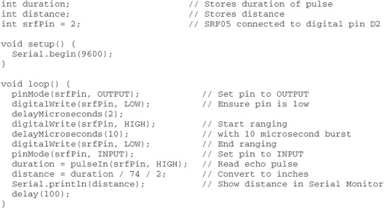
To use, compile and upload the sketch, then open the Serial Monitor window to view the results.

Figure 43-15 Basic connection diagram for the Devantech SRF05 ultrasonic sensor to the Arduino microcontroller.
![]()
Be careful when connecting the SRF05 to avoid swapping the 5V and Gnd connections, or you’ll reset your Arduino to failsafe mode (its internal fuse “blows” and won’t reset itself until you remove power). Figure 43-15 shows connection to the SRF05 from the component side, that is, the side with the LED, ICs, and other surface-mount parts. The two ultrasonic elements are on the other side. Carefully observe the 5V and Gnd pins.
PROGRAMMING THE ENHANCED ULTRASONIC SENSOR
If you don’t care to do the time-of-flight arithmetic in your microcontroller, or you’re using a microcontroller that lacks the ability to time events with the accuracy needed for ultrasonics, you can instead use a distance-measuring sensor that performs all the math for you. The output of the sensor is digital data (usually as a serial data stream) of the measured distance.
There are a variety of choices. Staying with the Devantech line, there’s the SRF02, which has a built-in microcontroller that does the math for you. The sensor requires that your microcontroller have I2C I/O lines; many do these days. (You can also use the ranger in serial mode; see the manufacturer’s spec sheet for details.)
Connection is fairly simple; Figure 43-16 shows the SRF02 hooked up to an Arduino. As with the previous warning for the SRF05, be very careful not to flip the 5V and Gnd connections.
The control sketch is shown in srf02.pde. To use, compile and upload the sketch, then open the Serial Monitor window to view the results.
srf02.pde
To save space, the program code for this project is found on the RBB Online Support site. See Appendix A, “RBB Online Support,” for more details.
ULTRASONIC SENSOR SPECS
Not all ultrasonic sensors offer the same characteristics. Read the specifications to better match the sensor to your task. Things to consider:
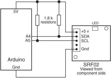
Figure 43-16 Connection diagram for the Devantech SRF02 ultrasonic sensor to the Arduino microcontroller, using I2C serial communications.
Working distance: Ultrasonic sensors have a minimum and maximum effective distance. For sensors like the SRF08, the minimum range is about 2 inches; the maximum about 20 feet. Some sensor ranges are more, some less. A very small minimum range is handy when using ultrasonic sensors in arms and grippers.
Sensitivity: The term “sensitivity” can refer not only to the resolving power of the sensor (see “Resolution,” next), but also to the ability of the sensor to accurately detect objects at a distance. In addition to the design of the receiver electronics, sensitivity is affected by things you can’t easily control: temperature, humidity, even wind, if you’re using the sensor outdoors.
Resolution: The frequency of the sound dictates its ability to detect small or thin objects. The 40-kHz sound waves used in low-cost ultrasonic sensors are fairly coarse. That equates to roughly 8.5mm from peak to peak of each wave. This means the smallest object an ultrasonic sensor operating at 40 kHz can fully resolve is less than half an inch. (In practice, most 40-kHz sensors can detect objects smaller than 8.5mm, but the readings are not always dependable.) Resolution is decreased when there’s a lot of air movement, or when the sensor is used near sources of heat, like hot pavement outdoors or an indoor air duct.
Beam spread and pattern: The typical ultrasonic sensor has a fairly wide cone-shaped echo pattern. The maximum distance of the sensor changes for objects that are off center (not aligned at 0°). On some, the far end of the cone is very wide; these are useful when you want to take in a large area. On others, the cone is very narrow. These so-called pencil-thin sound beams are useful when you want your robot to measure objects some distance away from itself and ignore closer objects that aren’t straight ahead.