
Chapter 31
Common Electronic Components for Robotics
Components are the things that make your electronic projects tick. Any given robot project might contain a dozen or more electronic components of varying types, including resistors, capacitors, integrated circuits, and light-emitting diodes.
In this chapter, you’ll learn about the components commonly found in electronics for robotics, and the roles they play in making the circuits work. We’ve got a lot of ground to cover, so let’s get started.
But First, a Word about Electronics Symbols
Electronics use a kind of specialized road map to tell you what components are being used in a circuit and how they are connected together. This pictorial road map is called the schematic; it is a blueprint that tells you just about everything you need to know to build the circuit.
Schematics are composed of special symbols that are connected with intersecting lines. The symbols represent individual components, and the lines are the wires that connect these components together. The language of schematics, while far from universal, is intended to enable most anyone to duplicate the construction of a circuit with little more information than a picture.
Forget what you might have read in some of the other books—learning how to read a schematic isn’t hard. Especially as it relates to robotics, all it takes is learning the meaning of a few basic symbols.
In this chapter you’re introduced to the symbol for each of the primary electronic components. These symbols are combined with those shown in Figure 31-1 that show how the various components are wired together. Purely for example purposes, Figure 31-2 shows how some symbols are interconnected to build a simple circuit—push the switch and the light-emitting diode turns on.
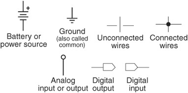
Figure 31-1 Basic schematic symbols used for wiring circuits. There are variations of those shown here, but these are the wiring symbols used throughout this book.

Figure 31-2 Example of a basic circuit, shown in schematic form. It consists of a battery, switch, resistor, and light-emitting diode. In many instances, the symbols are self-explanatory or pictorially descriptive.
There are hundreds of different electronic components, but only a small handful see regular use in electronic circuits for robotics. So instead of listing them all, I’ll cover only those that you’re most likely to encounter and use.
Fixed Resistors
Besides wire, resistors are the most basic of all electronic components. A resistor opposes the passing of current through it. It’s like squeezing down a rubber hose to keep water from flowing through. Fixed resistors (there are also variable resistors, discussed next) apply a predetermined resistance to a circuit.
By using resistors of different values in a circuit, different parts get varying amounts of current. The careful balance of current is what makes the circuit work.
HOW RESISTORS ARE RATED
The standard unit of value of a resistor is the ohm, represented by the symbol Ω. The higher the ohm value, the more resistance the component provides to the circuit. The value on most fixed resistors is identified by color-coded bands, as shown in Figure 31-3 (you can’t see the colors here, but you get the idea). The color coding starts near the edge of the resistor and comprises four, five, and sometimes six bands of different colors. Most off-the-shelf resistors for amateur projects use standard four-band color coding. They’re the easiest to find, and the least expensive.
To read the value, start with the band closest to the edge and decode the colors using Table 31-1. (For your convenience, the same chart is duplicated in Appendix D, “Electronic Reference.”)

Figure 31-3 Component outline and schematic symbols for a resistor. In this book the hollow rectangle is used for resistors, but you may encounter the “sawtooth” symbol used in schematics elsewhere.
Table 31-1 Resistor Color Code Chart
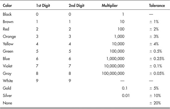
The first and second colors are the first and second digits of the value; the third color is the multiplier, the number of zeros you need to add. For example, if the first color is brown, the second color is red, and the third color is orange:
Brown = 1
Red = 2
Orange = Multiply by 1000 (the same as simply adding three zeros)
which gives you 12,000.
The fourth band in a four-band resistor is the tolerance, which is the amount (in percentage form) that the resistor may actually vary from its printed value. For example, a silver band means the resistor has a 10 percent tolerance; assuming a value of 12,000, 10 percent is 1200. That means the actual value of the resistor can be anything between 10,800 and 13,200.

Note the ± in front of the tolerance values in Table 31-1. That means + or - the indicated percentage. It can go both ways.
So-called precision resistors have a tolerance of less than 1 percent. Generally, these have five or more bands. The color coding is the same, but the extra bands provide more accurate numbers.
High-precision resistors are virtually never needed in the typical robotics circuits, and you can basically forget about them. The information is provided here so you know about the variations you can encounter when buying resistors new and as surplus.
The ohm value of resistors can vary from very low to very high. To make it easier to notate higher resistance values, resistors employ a common shorthand.
![]() The letter k (or K) is used to denote 1000. So a resistor with a value of 5 kΩ is the same as 5000 Ω. Sometimes the Ω symbol is dropped, because it’s understood. So you may also see the resistor noted with just 5k.
The letter k (or K) is used to denote 1000. So a resistor with a value of 5 kΩ is the same as 5000 Ω. Sometimes the Ω symbol is dropped, because it’s understood. So you may also see the resistor noted with just 5k.
![]() The letter M is used to denote one million, 1,000,000. A resistor with a value of 2 MΩ has a value of two million (2,000,000) ohms, or 2 megohms for short.
The letter M is used to denote one million, 1,000,000. A resistor with a value of 2 MΩ has a value of two million (2,000,000) ohms, or 2 megohms for short.
![]() Resistor notations for decimal values can vary depending on the country of origin. In the United States, a 4.7 ohm resistor is notated simply as 4.7 Ω. But some countries, like the United Kingdom and Australia, often use a different system, where the letter R replaces the decimal point, as in 4R7. Similarly, a 4.7 kΩ resistor is shown as 4k7.
Resistor notations for decimal values can vary depending on the country of origin. In the United States, a 4.7 ohm resistor is notated simply as 4.7 Ω. But some countries, like the United Kingdom and Australia, often use a different system, where the letter R replaces the decimal point, as in 4R7. Similarly, a 4.7 kΩ resistor is shown as 4k7.
Resistors are also rated by their wattage. The wattage of a resistor indicates the amount of power it can safely pass through its body without burning up—the correct term for this is power dissipation. Resistors used in high-load, high-current applications, like motor control, require higher wattages than those used in low-current applications. The majority of resistors you’ll use for hobby electronics will be rated at 1/4 or even 1/8 of a watt.
TESTING THE VALUE OF A RESISTOR
You can readily test the value of any resistor, as shown in Figure 31-4.
1. Dial the multimeter to read ohms. If your meter is not autoranging, select a maximum range just above the marked value of the resistor. (If you don’t know the value, select a high-resistance range to start.)
2. Connect the black (− or COM) lead to one end of the resistor; connect the red lead to the other end.
3. Read the result on the multimeter. If not using an autoranging meter, try a lower-resistance range to improve the accuracy of the measurement. If the meter shows over range (Over range indication, or the meter flashes 1.---) go back up one range.
COMMON APPLICATIONS FOR RESISTORS
Of the myriad uses of resistors in electronic circuits, two stand out as among the most common. We’ll concentrate on those.

Figure 31-4 How to check the value of a resistor using a multimeter. Dial the meter to read ohms, and, if the meter is not autoranging, select a range just higher than the expected resistance value.

Figure 31-5 Resistors are commonly used to alter the voltage levels in a circuit. Two resistors connected in series as shown form a voltage divider. The actual voltage between the resistors depends on the values of the resistors. The readings shown here assume two resistors of the same value.
Using Resistors to Divide a Voltage
Remember that a resistor literally resists current flowing through it. In a working circuit this feature can be used to control voltage, since current, voltage, and resistance are all related—learn more about this later in “Understanding Ohm’s Law.”
Picture two resistors strung together like that in Figure 31-5. This is called a series connection, because the two resistors are in series with one another. (If they were side by side in the circuit, they’d be said to be in parallel. We don’t need to investigate this connection scheme right now, so we’ll move on.)
The circuit shown is powered by a 5-volt supply. The voltage at the point where the two resistors are connected in the middle will be somewhere between 0 and 5 volts. Exactly what that voltage is depends on the values of the resistors.
![]() If both resistors are of equal value, the voltage at the center is exactly one-half the supply voltage, or 2.5 volts.
If both resistors are of equal value, the voltage at the center is exactly one-half the supply voltage, or 2.5 volts.
![]() If the resistors are not the same value, the voltage is a ratio of the difference of their resistance. For example, if the top resistor is 5 kΩ and the bottom resistor is 10 kΩ, the voltage at the center is 3.33 volts.
If the resistors are not the same value, the voltage is a ratio of the difference of their resistance. For example, if the top resistor is 5 kΩ and the bottom resistor is 10 kΩ, the voltage at the center is 3.33 volts.
How do you come up with these voltages, other than testing them with a multimeter each time? All it takes is some simple math. See Figure 31-6; the top resistor is referred to as R1, and the bottom is R2.
![]()
Let’s test this formula by plugging in the 5 kΩ and 10 kΩ values of the resistors and the 5 volts from the power supply. The formula becomes:
![]()
or, to simplify:
5 × 0.66 = 3.3
Using Resistors to Limit Current
Many electronic components, notably light-emitting diodes and transistors, will suck up as much current as the power supply will provide. This is bad because these components will burn out if they receive too much current. They’re made to handle only a certain amount of current, and beyond that they are permanently damaged.
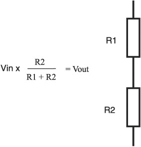
Figure 31-6 The basic (and simple) formula for calculating the divided voltage, when two resistors of unequal value are wired in series.
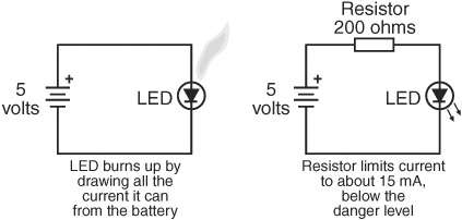
Figure 31-7 Another common use of resistors is to limit current; such a resistor is used to prevent a light-emitting diode (LED) from drawing too much current from its power source. Without a resistor to limit current, the LED will quickly burn out.
By stringing a resistor in series with these other components you can limit the amount of current they receive. This, after all, is the main purpose of a resistor … to resist current.
Figure 31-7 shows a very typical wiring diagram of a battery illuminating a light-emitting diode, also known as an LED. To prevent the LED from frying because it’s consuming too much current, a resistor is placed between it and the positive side of the battery. The circuit uses a 200 Ω resistor to limit the current. But how do we arrive at this value?
Again, all it takes is a little bit of math, plus knowing some things about the typical LED.
![]() First, most LEDs will burn out if they consume—also referred to as draw—more than about 30 milliamps (30 mA). So we want to make sure the LED gets less, and perhaps substantially less, than this amount of current. For example purposes, we wish to have the LED receive no more than 15 mA.
First, most LEDs will burn out if they consume—also referred to as draw—more than about 30 milliamps (30 mA). So we want to make sure the LED gets less, and perhaps substantially less, than this amount of current. For example purposes, we wish to have the LED receive no more than 15 mA.
![]() Second, you need to know the forward voltage drop across the LED. This is literally the amount of voltage that is lost when current is passed through the component. The typical voltage drop of an LED is 1.5 to 3.0 volts, though this can vary pretty widely when you start using some of the specialty LEDs. For our purposes, we’ll assume 2.0 volts for the drop.
Second, you need to know the forward voltage drop across the LED. This is literally the amount of voltage that is lost when current is passed through the component. The typical voltage drop of an LED is 1.5 to 3.0 volts, though this can vary pretty widely when you start using some of the specialty LEDs. For our purposes, we’ll assume 2.0 volts for the drop.
Apply this simple formula to determine the value of the resistor:
![]()
Vin is 5, and Vdrop (the voltage drop) is 2.0. We want to limit current to 15 milliamps, so the formula becomes
![]()
or
![]()
Notice that the current draw for the LED is a decimal fraction; gotta do it this way because the formula assumes amps, not milliamps (there are 1000 milliamps in 1 amp).
Resistors with four color bands come in only specific standard values, and, as it happens, 200 ohms is a standard value. When your calculation results in a nonstandard resistor value, pick the next-higher standard value. This way, the worst thing that’ll happen is that the LED won’t glow quite as brightly.
In addition to calculating the resistance value, you often need to come up with the wattage value, too. For most circuits you’ll be fine with the standard ⅛-and ¼-watt resistors, but how do you know if you need a bigger wattage? It’s easy when you use Ohm’s law, presented next.
UNDERSTANDING OHM’S LAW
In the early 1800s, German physicist Georg Ohm experimented with the relationships between voltage, current, and resistance. He came up with a method of accurately calculating these relationships, and this became Ohm’s law.
Figure 31-8 shows the basic triad that makes up the law—it’s called the Ohm’s law triangle. The triangle is pretty clever, because it indicates the math you do to calculate one value when you know the other two. In all cases, you use either multiplication or division, also shown in the figure.
V stands for voltage (note: in some texts describing Ohm’s law, voltage is shown as E).
R stands for resistance.
I stands for current (it’s not C, as that stands for the capacitance of a capacitor, as in flux capacitor).
Example Ohm’s Law Calculation
Let’s just take one of the formulas, the one for calculating V (voltage). For that, you need to know two of the other elements of the triangle, I (current, in amps) and R (resistance). The formula is:
V = I × R
Suppose the current is 1.2 amps, and the resistance is 50 ohms. Simply multiply 1.2 times 50; the result is 60, for 60 volts.
Calculating Power (Watts)
You can use an extension of Ohm’s law to calculate power dissipation in a circuit. This is helpful to ensure that the wattage of the resistors you choose is high enough. Higher-wattage resistors are bigger and can handle more power passing through them.
The extension isn’t part of the simple Ohm’s law triangle, but is a more complicated variation involving a wheel. If you’re interested in learning more about calculating power and watts, refer to Appendix D, “Electronic Reference,” for a brief discussion of using the Ohm’s law wheel. For now, though, we only need to apply one of the 12 formulas of the wheel.
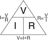
Figure 31-8 The Ohms law triangle, a mnemonic diagram that shows how to calculate the missing value when two other values are known. You can calculate for resistance, voltage, or current (current is referenced as the letter I).
Let’s return to the example of selecting a resistor to limit current to an LED. The formula to calculate power is very simple:
V × I = W
![]() V = voltage through the LED. This includes the voltage drop through the LED; from the previous example this voltage is 3.0.
V = voltage through the LED. This includes the voltage drop through the LED; from the previous example this voltage is 3.0.
![]() I = current to the LED. From the previous example this is 15 mA, or .015.
I = current to the LED. From the previous example this is 15 mA, or .015.
![]() W is the power dissipation, in watts. The resistor needs to be rated to dissipate at least this amount of power.
W is the power dissipation, in watts. The resistor needs to be rated to dissipate at least this amount of power.
Substituting the actual values, you get
3.0 × 0.015 = 0.045
The answer is in whole watts; 0.045 is less than 1/20 of a watt, so the standard 1/8-watt resistor is more than enough.
Potentiometers
Potentiometers are technically variable resistors. They let you “dial in” a specific resistance. The actual range of resistance is determined by the upward value of the potentiometer, and this upward value is how the potentiometer is marked. As with fixed resistors, the values are in ohms. For example, a 50 kΩ potentiometer will let you dial in any resistance from 0 ohms to 50,000 ohms.
Potentiometers (or pots for short) are of either the dial or the slide type. The dial type shown in Figure 31-9 is the most familiar and is used in such applications as radio volume and electric blanket thermostat controls. The rotation of the dial is nearly 360°. In one extreme, the resistance through the potentiometer is zero; in the other extreme, the resistance is the maximum value of the component.
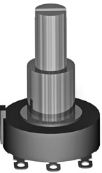
Figure 31-9 A potentiometer is a variable resistor. Turn the shaft of the potentiometer and its resistance changes.
LINEAR OR AUDIO TAPER
As you turn the dial of a potentiometer, the resistance varies from the lower extreme—usually 0 ohms, or very close to it—to the indicated value of the pot. The scale of the change is dependent on the internal construction of the component. There are two scales: linear and audio (also called logarithmic). The scale is referred to as the taper of the potentiometer.
![]() With linear taper, the most common, the value changes in proportion to the setting of the dial. For example, with a 10 kΩ pot, turning it a quarter of the way will yield 1/4 of the full scale, or 2.5 kΩ. For nearly everything you do in robotics you’ll want a linear taper potentiometer.
With linear taper, the most common, the value changes in proportion to the setting of the dial. For example, with a 10 kΩ pot, turning it a quarter of the way will yield 1/4 of the full scale, or 2.5 kΩ. For nearly everything you do in robotics you’ll want a linear taper potentiometer.
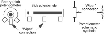
Figure 31-10 Component outline and schematic symbols for a potentiometer (or “pot” for short). The wiper is the center connection of the pot. It’s the wiper connection that provides the varying resistance value.
![]() With audio taper, the value of the potentiometer is a logarithmic function of the position of the dial. Given a 10 kΩ pot, the component still varies from 0 Ω to 10 kΩ; however, the change is not a straight line but a curve that’s especially steep. Audio taper pots are a fairly common find in the surplus market. You don’t want one of these unless you’re working on an audio project.
With audio taper, the value of the potentiometer is a logarithmic function of the position of the dial. Given a 10 kΩ pot, the component still varies from 0 Ω to 10 kΩ; however, the change is not a straight line but a curve that’s especially steep. Audio taper pots are a fairly common find in the surplus market. You don’t want one of these unless you’re working on an audio project.
USING A POTENTIOMETER
Most pots have three connections (see Figure 31-10), which basically form two resistors in series. In fact, potentiometers behave just like two resistors in series, and they can be used for the same kinds of things; for example, as voltage dividers. The ratio of the values of the two resistors used in the divider determine the voltage.
As shown in Figure 31-11, the two terminals on either side of the potentiometer function like the top of the fixed resistor R1 in Figure 31-6, and the bottom of the fixed resistor R2. The center terminal, called the wiper, is the connection between R1 and R2. As you turn the dial of the pot, you vary the ratio between the two resistances.
You can quickly test the operation of a potentiometer by connecting it to a multimeter (see Figure 31-12).
1. Dial the multimeter to read ohms. If your meter is not autoranging, select a maximum Ω just above the marked value of the potentiometer.
2. Connect the black (− or COM) lead to the center wiper terminal of the pot, and connect the red lead to either of the end terminals.
3. Slowly rotate the pot in one direction or the other, and watch the resistance go up and down.
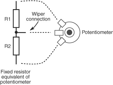
Figure 31-11 A potentiometer is basically two resistors wired in series, like that in Figure 31-5. Except in a pot, the values of the two resistors are constantly changing as you rotate the dial.

Figure 31-12 How to check the value of a potentiometer using a multimeter. The concept is the same as when testing a resistor. Turn the dial as you test to watch the resistance value change.
OTHER TYPES OF VARIABLE RESISTORS
Potentiometers are the most common type of variable resistor, but there are several other kinds you’ll encounter in your robot-building lifetime. The two most often used are photoresistors and the force-sensitive resistor.
![]() Photoresistors are sensitive to light. Their value changes as the intensity of the light varies. Photoresistors often go by the names photocell and CdS cell; the CdS comes from cadmium sulfide, the mixture of chemicals that make the component sensitive to light.
Photoresistors are sensitive to light. Their value changes as the intensity of the light varies. Photoresistors often go by the names photocell and CdS cell; the CdS comes from cadmium sulfide, the mixture of chemicals that make the component sensitive to light.
![]() Force-sensitive resistors, or FSRs, register force or pressure against them. The resistance of the component goes up or down as the force/pressure changes. There are numerous kinds of FSRs used for various kinds of sensing jobs. For example, a flex sensor provides a varying resistance as it’s twisted or bent. For others, resistance changes as any part of the membrane of the component is pressed against.
Force-sensitive resistors, or FSRs, register force or pressure against them. The resistance of the component goes up or down as the force/pressure changes. There are numerous kinds of FSRs used for various kinds of sensing jobs. For example, a flex sensor provides a varying resistance as it’s twisted or bent. For others, resistance changes as any part of the membrane of the component is pressed against.
FYI
Read more about photoresistors in Chapter 44, “Robotic Eyes,” where you’ll learn how to use CdS cells to make your robot respond to light. Be sure to check out Chapter 42, “Adding the Sense of Touch,” for additional details about FSRs.
READING POTENTIOMETER MARKINGS
Unlike fixed resistors, potentiometers aren’t marked with a color code. Instead, their value is marked either directly—for example, 10,000 or 10K—or indirectly using a decade numbering system. In this system the value is a three-digit number such as 503, which means 50, followed by three 0s, or 50,000. The number is given in ohms, meaning the pot is 50 kΩ.
Capacitors
After resistors, capacitors are the second most common component found in the average robotics electronic project. Capacitors serve many purposes. They can be used to delay the action of some portion of the circuit or to remove bothersome electrical noise within a circuit. These and other applications depend on the ability of the capacitor to hold an electrical charge for a predetermined period of time.
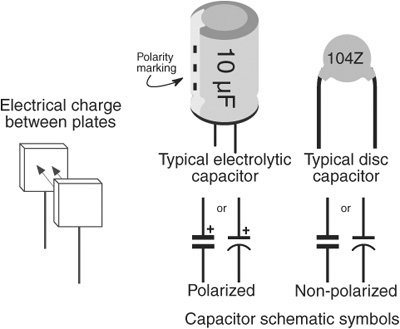
Figure 31-13 Component outline and schematic symbols for two popular styles of capacitors. Capacitors may be polarized or nonpolarized. When using polarized capacitors, there will be a polarity marking on the body of the component. Be sure to properly orient the capacitor in the circuit.
Capacitors come in many more sizes, shapes, and varieties than resistors, though only a small handful are truly common. However, most all capacitors are made of the same basic stuff: two or more conductive elements are separated by an insulating material called the dielectric (see Figure 31-13).
This dielectric can be composed of many materials, including air, paper foil, epoxy, plastic, even oil. When you select a capacitor for a particular job, you must generally also specify the dielectric. The most common are summarized in Table 31-3, later in this chapter, along with their common uses.
HOW CAPACITORS ARE RATED
Capacitors have two important ratings:
![]() Capacitance. Capacitance is the ability of the component to hold a charge. The larger the capacitance, the longer the charge is retained.
Capacitance. Capacitance is the ability of the component to hold a charge. The larger the capacitance, the longer the charge is retained.
![]() Dielectric breakdown voltage. At higher voltages the dielectric becomes partially or completely electrically conductive and the capacitor no longer functions as it should. The capacitor must be used below this voltage.
Dielectric breakdown voltage. At higher voltages the dielectric becomes partially or completely electrically conductive and the capacitor no longer functions as it should. The capacitor must be used below this voltage.
Capacitance is measured in farads. The farad is a large unit of measurement, so the bulk of capacitors available today are rated in microfarads; one microfarad is a millionth of a farad.
When the capacitor is under 1 microfarad, its value may be shown as a decimal point number—for example, 0.1 for one-tenth of a microfarad. Or it may be shown as a nanofarad. A nanofarad is a thousandth of a microfarad—that 0.1 microfarad capacitor is instead listed as 100 nanofarad. Same value, different way of expressing it. An even smaller unit of measure is the picofarad, or a millionth of a microfarad.
The “micro-” in the term microfarad is most often represented by the Greek “mu” (µ) character, as in 10 µF, or 10 microfarads. Keeping up with the shorthand, the nanofarad is nF, and the picofarad is pF.
In older books and magazines on electronics you may see microfarad shortened to mfd. Example: 10 mfd is 10 microfarads (10 µF). Mfd isn’t used as much today, but it’s good to know what it means in case you want to try out an older circuit you find at the library.
HOW CAPACITORS ARE MARKED
Capacitors are routinely marked with at least their capacitance value; many capacitors are also marked with value tolerance notation and a breakdown voltage. Additionally, capacitors that are polarized—they have a + and a − lead—also carry a polarization marking.
Capacitance Value
The capacitance values for some capacitors are printed directly on the component. This is true of larger capacitors with values of 1 µF or higher, if for no other reason than that their larger physical size allows the manufacturer to directly print the value on the component.
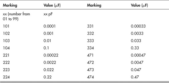
But for other capacitors, things aren’t always so simple. Smaller capacitors often use a common three-digit decade marking system to denote capacitance. The numbering system is easy to use if you remember it’s based on picofarads, not microfarads.
A number such as 104 means 10, followed by four zeros, as in
100,000
or 100,000 picofarads. To make the conversion, move the decimal point to the left six spaces: 100,000 becomes 0.1. Therefore, that 104 capacitor is 0.1 µF, or 100 nF. Note that values under 1000 picofarads do not use this numbering system. Instead, the actual value, in picofarads, is listed, such as 10 (for 10 pF). Table 31-2 provides a quick glance at how several common capacitor number markings convert to their µF (microfarad) equivalents.
Table 31-2 Capacitor Value Reference
![]()
As with resistors, what’s printed on a capacitor may not exactly match its real value. The accuracy of the stated value can vary widely, typically much more than with resistors. There are several ways to indicate capacitor tolerance. Rather than take up the space here, I’ve uploaded a guide on capacitor selection to the RBB Online Support site, described in Appendix A.
Dielectric Breakdown Voltage Value
The dielectric breakdown voltage is specified only for certain capacitors. For those that have it, the voltage is marked directly, such as “35” or “35V.” Sometimes, the letters WV are used after the voltage rating. This indicates the working voltage. You should not use the capacitor in a circuit with a voltage that exceeds this value.
On capacitors without a breakdown voltage printed on them you must estimate the value based on the type of dielectric it uses. This is an advanced topic and not covered in this book; nevertheless, it seldom comes up in electronics for robotics because most circuits use 12 volts or less, and most capacitors have a rated breakdown voltage of 25 to 35 volts. As a safety margin, select a capacitor with a breakdown voltage at least double the operating voltage of the circuit.
Polarization Marking
Some capacitors are polarized. Markings on the capacitor indicate the + or the – terminal.
If a capacitor is polarized, it is extremely important that you follow the proper orientation when you install the capacitor in the circuit. If you reverse the leads to the capacitor—connecting the + side to the ground rail, for example—the capacitor may be ruined. Other components in the circuit could also be damaged.
By convention, the polarizing mark on aluminum electrolytic capacitors is typically the − (negative) lead. The polarizing mark on tantalum electrolytic capacitors is typically the + (positive) lead.
UNDERSTANDING CAPACITOR DIELECTRIC MATERIAL
Capacitors are classified by the dielectric material they use. The most common dielectric materials are listed in Table 31-3. The dielectric material used in a capacitor partly determines which applications it should be used for.
COMMON APPLICATIONS FOR CAPACITORS
Unlike resistors, for which it’s easy to demonstrate practical applications in a circuit, capacitors are a bit more nebulous. They tend to work by interacting with other components, rather than doing things just on their own.
Capacitors are often used to filter, or remove, the rapid variations of an input voltage, leaving only a steady voltage. This is quite useful in all kinds of electronics, because some components produce large, instantaneous “glitches” of voltage. These glitches, referred to as power line noise, may disrupt neighboring components, especially integrated circuits.
Capacitors may also be used with resistors as part of a timing circuit. The value of the capacitor determines how long an event lasts—timing is controlled by how long it takes for the capacitor to charge or discharge its current. In all of the applications in this book involving the ubiquitous LM555 timer IC, for example, there’s always a capacitor that—when combined with at least one resistor—determines the duration of the timer.
Table 31-3 Capacitor Dielectric Materials (and Their Uses)

Diodes
The diode is a rudimentary form of semiconductor. Diodes (see Figure 31-14) are used in a variety of applications, and there are numerous subtypes. Here is a list of the most common that are used in the field of robotics (many of these topics are covered more fully in the projects found in Part 8):
![]() Rectifier. Let’s call this the “average” diode. It’s so called because one of its principal uses is to rectify AC current to provide DC only. It’s used for many other things, too, and is frequently employed in robotics circuits for motor control applications.
Rectifier. Let’s call this the “average” diode. It’s so called because one of its principal uses is to rectify AC current to provide DC only. It’s used for many other things, too, and is frequently employed in robotics circuits for motor control applications.
![]() Schottky. Special kind of diode that has improved performance. Used for applications where speed, low voltage drop, and “snap action” are needed.
Schottky. Special kind of diode that has improved performance. Used for applications where speed, low voltage drop, and “snap action” are needed.
![]() Zener. This diode limits voltage to a predetermined level. Zeners are used for low-cost voltage regulation.
Zener. This diode limits voltage to a predetermined level. Zeners are used for low-cost voltage regulation.
![]() Photo. All semiconductors are sensitive to light, but photodiodes are made especially for the task. Photodiodes and their close cousin, the phototransistor, are frequently used as light sensors in robotics projects.
Photo. All semiconductors are sensitive to light, but photodiodes are made especially for the task. Photodiodes and their close cousin, the phototransistor, are frequently used as light sensors in robotics projects.
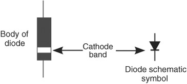
Figure 31-14 Component outline and schematic symbols for a diode. Diodes are polarized, as noted by a colored band. The band denotes the cathode, which is the negative (−) connection.
![]() Light-emitting. These diodes emit infrared or visible light when current is applied.
Light-emitting. These diodes emit infrared or visible light when current is applied.
![]() Laser. The now-common penlight lasers use a specially constructed diode that emits single-color laser light. They can be used for visual effects and some sensor applications.
Laser. The now-common penlight lasers use a specially constructed diode that emits single-color laser light. They can be used for visual effects and some sensor applications.
HOW DIODES ARE RATED
Diodes carry three important ratings: peak inverse voltage, current, and forward voltage drop (there are others, but these are the main ones).
The peak inverse voltage (PIV) rating roughly indicates the maximum working voltage for the diode. In the case of the common rectifier diodes, this maximum voltage is 50, 100, even 1000 volts, depending on the component. These voltages are well beyond what you’ll typically find in electronics for a robot, giving you a wide variety of components to choose from.
The current rating is the maximum amount of current that can be passed through the diode without risk of overheating and eventual self-destruction. Current ratings are in amps or, in the case of small diodes, milliamps. This rating is very critical in robotics applications, where it’s common to have circuits that require more current than what the average diode can handle.
Forward voltage drop is the amount of voltage that is essentially lost when it passes through the diode. The voltage drop affects the overall behavior of the diode; for example, with a very low drop, the diode is faster-acting.
UNDERSTANDING DIODE POLARIZATION
All diodes are polarized, and they have positive and negative terminals. The positive terminal is called the anode, and the negative terminal is called the cathode.
You can readily identify the cathode end of a diode by looking for a colored band or stripe near one of the leads. Figure 31-14 shows a diode that has a band at the cathode end. Note how the band corresponds with the heavy line in the schematic symbol for the diode.
EXPLORING THE COMPOSITION OF DIODES
Among other variations, diodes are available in two basic flavors, germanium and silicon, which indicate the material used to manufacture the active junction (the part that conducts current) within the diode. The two types of materials also have an effect on the forward voltage drop of the device: about 0.7 volts for silicon and 0.3 volts for germanium.
Since the voltage drop can change the behavior of the circuit, you should always be careful which of these two kinds you use. If the circuit doesn’t say, a silicon diode is probably fine; if a germanium component is called for, be sure not to substitute a silicon type.
COMMON APPLICATIONS FOR DIODES
Like all other electronic components, diodes are used for a fantastically wide array of applications. Two serve as good examples of the beneficial role diodes play in circuits for robotics control: incremental voltage drop and reverse polarity protection.
In both of these examples, no attention is given to ensuring that the diodes selected for the task can adequately handle the current demands of the circuits. In an actual circuit you’ll need to determine the total current draw through the diode and make sure you pick one that is rated for that current.
Incremental Voltage Drop
Recall that diodes exhibit a forward voltage drop, whereby a certain amount of voltage is lost as current passes through the device. With silicon diodes, this drop is about 0.7 volts. You can use this “feature” of a diode to incrementally decrease a voltage in specific steps. Note that this isn’t real voltage regulation; if the voltage from the power supply goes up or down, so will the voltage on the other side of the diodes.
Reverse Polarity Protection
Connecting a battery backward to an electronic circuit can easily damage the circuit. You can prevent such damage by putting a diode in series with the positive power supply connection. This technique works because the diode passes current in one direction only: from anode to cathode. It won’t allow current to flow the other way.
Light-Emitting Diodes (LEDs)
All semiconductors emit light when an electric current is applied to them. This light is generally very dim and only in the infrared region of the electromagnetic spectrum. The light-emitting diode (LED; see Figure 31-15) is a special type of semiconductor that is expressly designed to emit copious amounts of light. Most LEDs are engineered to produce a specific color of light, as well as infrared and ultraviolet. Red, yellow, and green LEDs are among the most common, but blue, violet, and even white light (all-color) LEDs are available.
LEDs carry the same specifications as any other diode. The typical LED has a maximum current rating of 30 milliamps or less, though this varies greatly, and depends on size, type, even color. And like a diode, all LEDs exhibit a forward voltage drop—only it’s often much higher than that of a standard diode. Depending on the LED (and often related to its color), expect a voltage drop of between 1.5 and 3.5 volts. Some specialty high-brightness LEDs have even higher drops.

Figure 31-15 Component outline and schematic symbols for a light-emitting diode (LED). Diodes are polarized, and, depending on the component, the polarization may be noted by a flattened edge and/or a shorter lead. These denote the cathode, which is the negative (−) connection.
And, as with a standard diode, the terminals on an LED are its anode (+) and cathode (−). Rather than a white or colored stripe, most LEDs distinguish the two using other methods, as shown in Figure 31-15. Not all LEDs follow the same marking conventions, so you may need to experiment. (Usually nothing bad happens if you connect an LED backward—that is, if you switch the anode and the cathode—but the LED will not light.)
POWERING LEDS
LEDs are most often used in low-power DC circuits and are powered with 12 volts or less. Always remember that the component can be ruthlessly damaged if you expose it to currents exceeding its maximum rating. So, unless the LED has a built-in resistor, you always need to add one to limit the amount of current that flows through the LED. See the application examples for the resistor, mentioned previously in the chapter, which demonstrate this process.
SHAPE, SIZE, AND LIGHT OUTPUT
Light-emitting diodes come in all kinds of shapes and sizes. The most common are cylindrical and shaped with a domed top. Popular sizes are:
![]() T1, or miniature: 3mm in diameter
T1, or miniature: 3mm in diameter
![]() T1-3/4, or standard: 5mm
T1-3/4, or standard: 5mm
![]() Jumbo: 10mm
Jumbo: 10mm
While the most common LED is round, there are also square, rectangular, even triangular LEDs. The shapes are handy for different kinds of applications—the triangles look like arrows, so they can be used to show direction.
Multi-LED Displays
LEDs can come one in a package or as part of a larger package with other LEDs. Each individual LED in the package can be individually lit. Three common variations on the multi-LED theme are:
7-segment display: Has seven individual LEDs in special shapes to form a large numeral. By controlling which LEDs are on and off, the display can show numbers 0 through 9.
Bar graph display: Typically contains 10 miniature rectangular LEDs.
Dot matrix display: Contains rows and columns of dots; any number, letter, or special character can be created by lighting up certain dots.
LED COLORS
Most LEDs emit a single color, but others are designed to produce two or three colors. You can control which color is shown by applying current to various terminals on the LED (Figure 31-16).
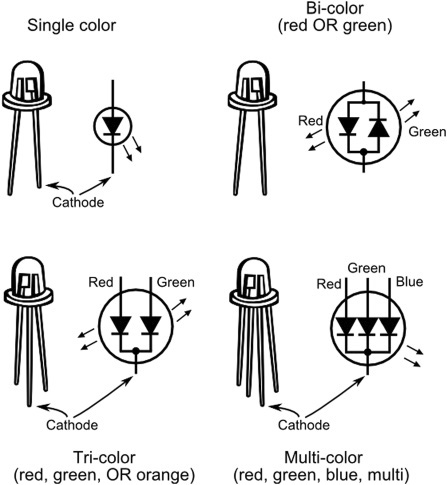
Figure 31-16 LEDs that display more than one color have additional connection points. The wiring of the connections depends on the type of LED. Shown here are several of the most common.
![]() A two color (or bicolor) LED contains red and green LED elements (other colors are possible too, but the red/green combination is the most common). You control which color is shown by reversing the voltage to the LED. You can also produce a yellowish-orange by quickly alternating the voltage polarity.
A two color (or bicolor) LED contains red and green LED elements (other colors are possible too, but the red/green combination is the most common). You control which color is shown by reversing the voltage to the LED. You can also produce a yellowish-orange by quickly alternating the voltage polarity.
![]() A tricolor LED is functionally identical to the bicolor LED, except that it has separate connections for the red and green diodes. You can produce the intermediate color of yellowish-orange by turning on both the red and green diodes at the same time.
A tricolor LED is functionally identical to the bicolor LED, except that it has separate connections for the red and green diodes. You can produce the intermediate color of yellowish-orange by turning on both the red and green diodes at the same time.
![]() A multicolor LED contains red, green, and blue LED elements. You control which color to show by individually applying current to separate terminals on the LED. These are also called RGB LEDs.
A multicolor LED contains red, green, and blue LED elements. You control which color to show by individually applying current to separate terminals on the LED. These are also called RGB LEDs.
There’s a bit of confusion as to what, exactly, constitutes bicolor and tricolor LEDs. Both can produce three colors: red, green, and yellowish-orange. The way they do it differs. Compounding the confusion is that some sources call a multicolor LED a tricolor LED, because it (rightly) contains three colors.
Common Anode or Cathode
To reduce the number of terminals coming out of the multidiode LED, all of the anodes, or all of the cathodes, of each diode in the device are wired together. When all the anodes are combined, the LED is said to be common anode. And when all of the cathodes are combined, it’s common cathode.
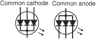
Which one you choose depends on what’s available and how the circuit is designed. Common cathode is more common among multiple-color LEDs; both common anode and common cathode are used in 7-segment and other LED displays. Be sure to match the device with the circuit plans you’re using.
Transistors
Transistors (see Figure 31-17) were designed as an alternative to the old vacuum tube. They’re used for many of the same things, either to amplify a signal or to switch a signal on and off. At last count there were several thousand different types of transistors available.
Transistors are divided into two broad categories: signal and power. You can usually tell the difference between the two merely by size.
![]() Signal. These transistors are used with relatively low current circuits, like radios, telephones, and some hobby electronics projects. They are available in either plastic or retro-looking metal cases. The plastic kind is suitable for most uses, but some precision applications require the metal variety. No projects in this book require great precision, so the cheap plastic signal transistor is good enough.
Signal. These transistors are used with relatively low current circuits, like radios, telephones, and some hobby electronics projects. They are available in either plastic or retro-looking metal cases. The plastic kind is suitable for most uses, but some precision applications require the metal variety. No projects in this book require great precision, so the cheap plastic signal transistor is good enough.
![]() Power. These transistors are used with high-current circuits, like motor drivers and power supplies. Power transistors come in metal cases, though a portion of the case (the back or sides) may be made of plastic.
Power. These transistors are used with high-current circuits, like motor drivers and power supplies. Power transistors come in metal cases, though a portion of the case (the back or sides) may be made of plastic.
Figure 31-18 shows several common varieties of transistor cases and how they are referred to, such as TO-92 and TO-220. The signal transistor is rarely larger than a pea and uses slender wire leads. The power transistor has a large metal case, to help dissipate heat, and heavy, spokelike connection leads.
HOW TO IDENTIFY A TRANSISTOR
Transistors are identified by a unique code, such as 2N2222 or MPS6519. Refer to a data book to ascertain the characteristics and ratings of the particular transistor you are interested in. Transistors are rated by a number of criteria, which are beyond the scope of this book. None of these ratings are printed directly on the transistor.
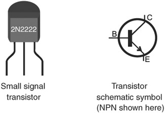
Figure 31-17 Component outline and schematic symbols for a transistor. The outline view is of a small signal transistor.
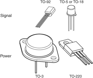
Figure 31-18 There are many shapes and sizes of transistors, but a common trait of most of them is that they have three connection wires. Larger transistors are generally used for applications involving high currents, such as powering motors. Shown are four popular transistor cases.
Transistors have three-or four-wire leads. The leads in the typical three-lead transistor are base, emitter, and collector. (A few transistors, most notably certain types of the field-effect transistor—or FET, for short—have a fourth lead. None of the circuits in this book use this type, which are not common anyway.)
NPN, PNP—TWO SIDES OF THE SAME COIN
Transistors can be either NPN or PNP devices. This nomenclature refers to the sandwiching of semiconductor materials inside the device. You can’t tell the difference between an NPN and a PNP transistor just by looking at them.

However, the difference is indicated in the catalog specifications sheet as well as by the schematic symbol for the transistor. In an NPN device, the arrow is shown leaving the transistor; in a PNP device, it’s the opposite. This differentiation helps you to quickly tell whether you should use an NPN or a PNP type transistor for the circuit.
ENTER THE MOSFET
Some semiconductor devices look and act like transistors and are actually called transistors, but in reality they use a different underlying technology. So far I’ve been talking about a class of transistor called the bipolar junction transistor, or BJT. These are by far the most common. Another form of transistor is the MOSFET. This collection of alphabet soup stands for metal-oxide semiconductor field-effect transistor. It’s often used in circuits that demand high current and high precision.

Wouldn’t you know it, but just to complicate things, MOSFET transistors don’t use the standard base-emitter-collector connections you just read about. Instead, they call them gate, drain, and source connections. And note, too, that the schematic diagram for the MOSFET is different from that of the standard transistor.
Like the bipolar junction transistor, MOSFETs come in two varieties: N-channel and P-channel. And, as before, you can’t tell the difference between an N-channel and a P-channel MOSFET just by looking at it.
![]()
The schematic symbols for the two types of MOSFETs are only ever-so-slightly different, and not all schematic diagrams bother to show which one is used in the circuit. You cannot substitute N-channel for P-channel, so when using these devices, be absolutely sure you’ve got the right ones in your hands.
Integrated Circuits
The integrated circuit, colloquially referred to as an IC or chip, forms the backbone of the electronics revolution. The typical integrated circuit comprises many transistors and other components. As its name implies, the integrated circuit is a discrete and wholly functioning circuit in its own right. ICs are the building blocks of larger circuits. By merely stringing them together you can form just about any project you envision.
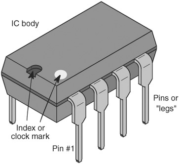
Figure 31-19 Integrated circuits come in a plastic rectangular body, with four or more connection pins, or legs. A printed index mark or notch shows the “top” of the component. Pin 1 is always the first pin when going counterclockwise.
Integrated circuits are enclosed in a variety of packages. The actual integrated circuit itself is just a tiny sliver inside this package. For the hobbyist, the easiest-to-use IC package is the dual in-line package (or DIP), like the one in Figure 31-19. The illustration shows an 8-pin DIP, but other sizes are common, too.
IDENTIFYING INTEGRATED CIRCUITS
As with transistors, ICs are identified by a unique code printed on the top. Codes may be a simple number sequence such as 7400 or 4017. This code indicates a type of device that is made by many different manufacturers. You can use this code to look up the specifications of the IC in a reference book.
More than likely, the number identifying the IC will contain letters that further distinguish it from other ICs of the same family, that is, ICs that do pretty much the same thing but have different operating characteristics or manufacturing technologies. The differences among these IC families are quite complex and well outside of what this book is about, but to get you started, let’s take the 7400 as an example.
The 7400, which dates back to the swingin’ 1960s, contains four digital NAND gates; NAND gates are one of several common forms of logic circuits used to create computers. Variations of this chip include:
![]() 7400—Base chip as originally manufactured.
7400—Base chip as originally manufactured.
![]() 74ALS00—Advanced low-power Schottky; enhanced lower-power version.
74ALS00—Advanced low-power Schottky; enhanced lower-power version.
![]() 74HCT00—CMOS version of the 7400 compatible with older devices.
74HCT00—CMOS version of the 7400 compatible with older devices.
And there are many others. When a circuit specifies just the base chip—the 7400 rather than a specific family member—it usually means that the circuit isn’t particularly picky, and you can use most any IC in that family.
Many ICs also contain other written information, including manufacturer catalog number and date code. Do not confuse the date code or catalog number with the code used to identify the device. Date codes can look like part numbers—9206 might mean the IC was made in June 1992.
MICROCONTROLLERS AND OTHER SPECIALTY ICS
Chips like the 7400 (and all its kin) are considered standard building blocks and are available from a variety of manufacturers. Add to these the thousands of specialty ICs that are unique to specific chip makers and perform unique tasks.
For robotics, the most common of these specialty ICs is the microcontroller, a type of all-in-one computer that is designed to directly connect with external inputs and outputs. Microcontrollers are more fully detailed in Chapters 35 through 40.
Still other specialty ICs might perform any of the following tasks:
![]() Sense the tilt of your robot to let you know if it’s fallen over (accelerometer)
Sense the tilt of your robot to let you know if it’s fallen over (accelerometer)
![]() Detect small changes in temperature and convert this information to a signal that can be read by a microcontroller (temperature sensor)
Detect small changes in temperature and convert this information to a signal that can be read by a microcontroller (temperature sensor)
![]() Convert one voltage to another, with very high efficiency (switching mode regulator)
Convert one voltage to another, with very high efficiency (switching mode regulator)
![]() Create sound effects and intelligible speech (sound and speech synthesizer)
Create sound effects and intelligible speech (sound and speech synthesizer)
![]() Control the operation and speed of a DC motor (H-bridge motor driver)
Control the operation and speed of a DC motor (H-bridge motor driver)
and, of course, many others.
As with standard-building-block ICs, specialty chips carry markings that indicate the manufacturer name and part number, date code, and other important information.
Switches
Most robots use at least one switch—to turn it off or to reset the thing when its programming goes bonkers. A lot of robots use multiple switches, for things like setting operating modes or detecting when the bot has bumped into a wall, chair leg, or person.
Switches come in a variety of shapes and sizes, but their overall functionality is universal: switches are composed of two or more electrical contacts. In one position of the switch, the contacts are not connected, and current doesn’t flow through the device. The switch is said to be open. In the other position, the contacts are connected together, and current flows. The switch is said to be closed (see Figure 31-20).
Poles: The most basic switch has a single pair—or pole—of contacts. But some switches are composed of several poles, so there are extra pairs of contacts—one switch functions as multiple switches all connected together. Multiple poles allow the switch to control multiple circuits at the same time.
Throws: The basic switch has two positions, on or off. But some switches have more positions. Each position is called a throw. Instead of just on or off, a two-throw switch is on-on. Each “on” can connect to a different part of the circuit. Most often, multiple throws are combined with multiple poles to provide all manner of choices.
Momentary position: Switches that are spring-loaded are called momentary, because when you release the switch it automatically goes back to its normal position. The most common type of momentary switch is the push button: press it, and the switch closes; release it, and the switch returns to open all on its own.
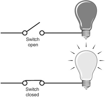
Figure 31-20 Basic function of a switch: When open, the light is off (unpowered). When closed, the switch completes the circuit, and the light turns on.

Figure 31-21 Common variations in switches indicate the number of poles and throws (positions). Common switches for use in robotics include single-pole, single-throw (SPST), and double-pole, double-throw (DPDT).
Switches are further defined by how they are operated. There are four principal types, and each is self-explanatory by its name: toggle, push-button, slide, and rotary.
MIXING AND MATCHING
Poles, throws, and momentary position can all be mixed together in various combinations. Switches follow a common nomenclature to describe how they function. Here are just a few of the combinations you’ll likely encounter (see Figure 31-21).
![]() Single-pole, single-throw (SPST) has one set of poles and one throw. It’s the basic, no-frills switch.
Single-pole, single-throw (SPST) has one set of poles and one throw. It’s the basic, no-frills switch.
![]() Single-pole, double-throw (SPDT) has one set of poles and two throws.
Single-pole, double-throw (SPDT) has one set of poles and two throws.
![]() Double-pole, single-throw (DPST) has two set of poles and just one throw. You can think of it as two SPST switches combined into one.
Double-pole, single-throw (DPST) has two set of poles and just one throw. You can think of it as two SPST switches combined into one.
![]() Double-pole, double-throw (DPDT) has two set of poles and two throws.
Double-pole, double-throw (DPDT) has two set of poles and two throws.
MOMENTARY AND CENTER-OFF
Add to the three main pole/throw combinations spring-loaded momentary and center-off positions. A DPDT switch with a center-off position is said to be on-off-on. One or both of the on positions may be momentary, that is, spring-loaded. Release the switch, and it returns to its off position.
When you read specifications about a switch, you may see something like this:
(on)-off-(on)
It describes a switch with a center-off position. The parentheses mean that the position is momentary.
NORMALLY OPEN, NORMALLY CLOSED
The contacts of a momentary switch can be either normally open or normally closed. The “normally” has to do with the position of the contacts when the switch is not being depressed.

In a normally open (NO for short) switch, the circuit is normally broken. Depressing the push button closes the contacts. It’s just the opposite with a normally closed (NC) switch: depressing the button opens the contacts.
Relays
Relays work like switches, but they are changeable under electronic control. Instead of a human (or dog, or whatever) pressing a switch to change the contact settings, in a relay it’s all done via electrical signals. Figure 31-22 shows the basic construction of a relay and how it works. As shown, the two basic parts of the relay are the coil and the contacts. In operation, when the coil is energized, the magnetic field that is created activates the switch contacts.
Because relays are essentially switches, they are defined in the same way: the poles and throws indicate the number of contacts. But unlike switches, most (but not all) relays are by their nature momentary. The switch contacts in a relay are activated when the relay is energized. Remove the juice from the relay, and the spring-loaded contacts go back to their original position.
COMMON RELAY TYPES
There are lots of different kinds and styles of relays out there, but most fall into one of the following three types (see Figure 31-23):
![]() The SPST (single-pole, single-throw) relay has four connections: two for the coil and two for the switch contacts. The contacts may be normally open (the most common) or normally closed.
The SPST (single-pole, single-throw) relay has four connections: two for the coil and two for the switch contacts. The contacts may be normally open (the most common) or normally closed.
![]() The SPDT (single-pole, double-throw) relay has five connections: two for the coil, as usual, and three for the switch contacts. The contacts are often labeled as Common, NC, and NO. You wire your circuit to Common and either the NC or the NO connection.
The SPDT (single-pole, double-throw) relay has five connections: two for the coil, as usual, and three for the switch contacts. The contacts are often labeled as Common, NC, and NO. You wire your circuit to Common and either the NC or the NO connection.
![]() The DPDT (double-pole, double-throw) relays are an extension of the SPDT. They have a separate set of pole contacts, for a total of eight connections.
The DPDT (double-pole, double-throw) relays are an extension of the SPDT. They have a separate set of pole contacts, for a total of eight connections.

Figure 31-22 Relays are electrically controlled switches. Energizing a coil with current activates the switch contacts. Many relays have two contacts, in addition to a common connection. These contacts are marked normally open (NO) and normally closed (NC). The notation refers to when the relay is not energized.
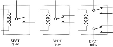
Figure 31-23 Three typical relay types used in robotics: single-pole, single-throw; single-pole, double-throw; and double-pole, double-throw.
SIZES OF RELAYS
Relays are “rated” by the amount of current that can be passed through their switch contacts. The more current, the larger the relay. For the typical desktop robot application, the smallest of relays are ideal: these are about the same size and shape as an integrated circuit.
Larger currents (loads) require bigger contact points, so if you’re operating a robot with a huge motor, you’ll need something more. As the relay gets bigger, properly operating it becomes much harder. For one thing, you need more drive current from your circuit to activate the relay. The standard setup of using a pea-sized signal transistor between your microcontroller and relay won’t cut it.
High currents can cause arcing and other unpleasant artifacts whenever the relay is energized and deenergized. Careless use of a heavy-duty relay can even result in the electrical contacts becoming welded together! These issues aren’t a problem as long as you stick with small relays and small motors—the stuff of the average desktop robot. Operating the motors of a big-brute combat robot is beyond the scope of this book, but there are guides and online sites that cover this topic. Do a Web search and visit your local library.
RELIABILITY OF RELAYS
Relays are electromechanical, and, because of this, over time they could wear out and fail. But, in truth, for the average small relay used on the average bot, you’d have to operate your little robotic pet for several years before the relay would give out.
Most relays are rated for 100,000 or more switches. The trick is to make sure your circuit doesn’t exceed the current rating of the relay contacts. The less complicated the construction of the relay, the longer it’ll last (and the cheaper it is to replace). The lowly reed relay (so called because the contact is a simple metallic reed inside a glass ampoule) can last for years and years.
… And the Rest
In the first season of the old TV show Gilligan’s Island, the characters of The Professor and Mary Ann didn’t even rate being mentioned in the opening theme song. Instead, they were referred to as “and the rest.”
The components that follow are part of “and the rest” when building robot electronics. These are important in their own right, to be sure, but are better left to examples in other chapters that show them in actual use. They include:
Speakers, to better hear your robot.
Microphones, to better your robot’s hearing you (is that even a proper sentence?). See Chapter 46, “Making and Listening to Sound,” for more on speakers and microphones.
Light-sensitive resistors, transistors, and diodes, to give your robot the gift of simple sight. These components are detailed more fully in Chapter 44, “Robotic Eyes.”
LCD displays, to let your robot communicate with you in words. Read more about how to use these in Chapter 47, “Interacting with Your Creation.”
On the Web: Stocking Up on Parts
So what parts should you get for your robotics lab? How many resistors, and what values, should you stock up on? That can be a tough question if you’re just starting out. The details would kill too many trees, so as a bonus to the readers of this book, I’ve outlined some suggestions (with suppliers and parts numbers) on the RBB Online Support site, described in Appendix A.