
Chapter 35
Understanding Microcontrollers
Microcontrollers have become the favorite method for endowing a robot with smarts. And there’s good reason: microcontrollers are inexpensive, have simple power requirements—usually just 5 volts—and most can be programmed using software on your PC. Once programmed, the microcontroller is disconnected from the PC and operates on its own.
A microcontroller is a computer-on-a-chip. It contains everything (or almost everything, depending on the exact model) that’s needed to be a fully functional computer. It contains a central processing unit that does the thinking, memory for storing programs and data, and multiple connections that allow it to interface with external devices. In all, the perfect brain for robots.
In this chapter you’ll learn about microcontrollers in general—what’s inside, how they differ, and why you might want to choose one kind over another. Then in Part 7 you can learn specific details about three very popular microcontrollers used in robot projects: the Arduino, PICAXE, and BASIC Stamp. These chapters include sample projects and programming code you can try for yourself. Find more in Part 8 and on the RBB Online Support site (see Appendix A for details).
All about Microcontroller Categories
Microcontrollers, or MCUs for short, come in all sizes, styles, and categories. Some are for esoteric applications, like running a car’s engine or controlling the operation of industrial furnaces. Others are general-purpose, designed for a wide variety of applications. The latter kind are the ones we’re most interested in. Figure 35-1 shows a low-cost modular microcontroller designed for experimentation—it contains the MCU itself, plus a liquid-crystal display and other components for learning about programming microcontrollers.
Here are other ways microcontrollers differ and the benefits of each type.

Figure 35-1 Example low-cost modular microcontroller, designed for learning and experimentation. It contains the microcontroller chip itself, plus a liquid-crystal display, button joystick, and other components.
8- 16-, OR 32-BIT ARCHITECTURE
As with your desktop computer, microcontrollers come with different data-processing architectures; these are denoted by the number of bits they process at one time.
![]() The oldest and simplest of microcontrollers used 4-bit processing. These are of little use to us today, and, besides, they’re no longer common in the consumer chip-selling marketplaces.
The oldest and simplest of microcontrollers used 4-bit processing. These are of little use to us today, and, besides, they’re no longer common in the consumer chip-selling marketplaces.
![]() On the other end of the spectrum are MCUs that handle 64 bits at a time. These are specialty chips used for high-end applications and, as such, tend to be expensive and more difficult to program. (Of course, these limitations could and probably will change as time marches on. That’s progress for you.)
On the other end of the spectrum are MCUs that handle 64 bits at a time. These are specialty chips used for high-end applications and, as such, tend to be expensive and more difficult to program. (Of course, these limitations could and probably will change as time marches on. That’s progress for you.)
![]() Middle-of-the-road microcontrollers handle 8, 16, or 32 bits at a time. The most common for amateur robotics is the 8-bit variety, which, despite handling “only” 8 bits at a time, is ideally suited to the vast majority of robot programming tasks. Eight-bit MCUs are the least expensive and the most widely available.
Middle-of-the-road microcontrollers handle 8, 16, or 32 bits at a time. The most common for amateur robotics is the 8-bit variety, which, despite handling “only” 8 bits at a time, is ideally suited to the vast majority of robot programming tasks. Eight-bit MCUs are the least expensive and the most widely available.

Recall that the bit is the smallest value that can be stored in the memory of a microcontroller or processed through its circuitry. A bit is either off or on. The two possible values for a bit are most commonly represented by the numerals 0 and 1. The value stored in the bit is not really a numeric “zero” or “one”; the 0 and 1 are used as a kind of shorthand. Other shorthands include LOW for 0 and HIGH for 1.
LANGUAGE PROGRAMMING
All microcontrollers need to be programmed for the task you want them to do. None “just work” out of the box (exception: they come preprogrammed with a demo).
There are two general methods of programming a microcontroller, which, for the lack of better terms, I’ll call low-level programmable and integrated-language programmable. These loosely defined terms relate to how the programming is stored and executed in the controller. Both kinds of microcontrollers are fully programmable.
Low-Level Programmable
The traditional way to program a microcontroller has been with assembly language, using your PC as a host development system. Assembly language appears arcane to newcomers, and for many it proves to be a stopping point in further study of microcontrollers. Making matters more complex is that the assembly language for one brand of microcontroller is different from that for another.
Fortunately, most microcontrollers today can also be programmed with a more user-friendly language, such as BASIC, C, or Pascal. These languages are much more approachable, making them easier to learn. You might already know a little (or a lot) about one or more of these languages, in which case you’re well on the road to programming a microcontroller. Software on your computer converts your program into so-called machine code, which can be directly read and used by the microcontroller (see Figure 35-2).
An example of a microcontroller that is low-level programmable is the Arduino, which actually uses the Atmel AVR (a popular 8-bit MCU) as its processor. As you’ll read in Chapter 37, “Using the Arduino,” this microcontroller is more than just a chip. It takes a holistic (whole system) approach that’s become very popular among robot builders and electronics experimenters.
Integrated-Language Programmable
In this type of microcontroller, the chip itself contains a kind of language interpreter. A program on your computer, a compiler, converts your program into an intermediate language that uses “tokens” to represent actions. The interpreter inside the microcontroller finishes the job of translating the tokens to the low-level code needed by the chip.
Examples of microcontrollers that use this approach include the BASIC Stamp and the PICAXE. Both are based on 8-bit MCUs. These two controllers are further detailed in their own chapters. See Chapter 38, “Using the PICAXE,” and Chapter 39, “Using the BASIC Stamp.”
Choice of Programming Language
A low-level programmable microcontroller is basically a blank canvas; it’s up to you what you put in it and how you do it. With these controllers you have an option of choosing the language you wish to use. These include:
BASIC: This language is popular with those just starting out in programming, as the language is designed for beginners—in fact, the B in BASIC stands for beginner. It’s also a favorite among those already familiar with a BASIC language for the PC, such as Visual Basic. BASIC is a more forgiving language than the others; for example, it’s not case-sensitive. It doesn’t care if you use different capitalizations to reference the same things.
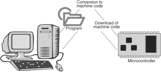
Figure 35-2 Programming cycle of a microcontroller. Programs are developed on a PC, where they are compiled to a machine-readable format, and then downloaded (usually via cable) to the microcontroller.
C: The language of choice for programming professionals, C has more strict syntax rules, so it’s often considered harder to learn. (In a spoken language, syntax is how the parts of speech are strung together to form a coherent statement. It’s the same in a programming language.) For all the bad rep C gets for being a stern schoolmaster, it’s actually not that much more difficult to learn than BASIC, at least not when it comes to microcontrollers.
Pascal: Considered a blueprint for modern structured programming, Pascal is a lesser-used language when it comes to microcontrollers (so there aren’t as many options for it), but it’s known for being easy to learn.
There are several other programming languages used in microcontrollers, including Forth, Java, Python, and C#. The choice of which language to use depends greatly on which one you’re more comfortable with and which offers the feature set you want to exploit in your robot work.
Three Steps in Programming a Microcontroller
No matter what system or language you use, there are three basic steps to programming a microcontroller. They are:
1. Use your personal computer to write your program with a text editor or other application. Many commercial programming languages come with a fancy editor, called an IDE, for integrated development environment. This single application combines the programming step with the other two that follow.
2. You then compile your program into a form of data that the MCU will understand. The microcontroller doesn’t know an “If” statement from a hole in the ground, and the job of the compiler is to convert the human-readable code you just wrote to the machine language the microcontroller understands.
3. After being compiled, the translated program is downloaded to the microcontroller. This is most often done using a USB or serial cable. Once downloaded, the program is immediately ready to be run inside the microcontroller. In fact, it will usually start running the moment the downloading process is complete.
Microcontroller Shapes and Sizes
All microcontrollers are integrated circuits, with anywhere from 8 to over 128 connection pins, depending on complexity. But you don’t always work with a microcontroller as a separate integrated circuit. Popular form factors of microcontrollers include (see Figure 35-3):
Chip-only: You work with the microcontroller at the bare IC level. The chip may or may not need any external components to operate. At a minimum, some need a voltage regulator and an oscillator or resonator as a clock source.
Carrier: In this variation the microcontroller IC is mounted on a carrier, which contains additional electronics. The carrier is itself the size and shape of a wide-profile integrated circuit: a 24-pin “double-wide” IC is common. This is the form factor of the BASIC Stamp and similar products. The carrier can be plugged into solderless breadboards for further experiments. Not all carriers are shaped like ICs. Some look more like long sticks, with one or two rows of connection pins.
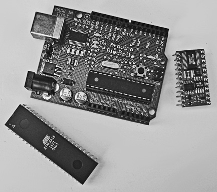
Figure 35-3 Three typical microcontroller form factors: bare integrated circuit (chip-only), carrier board, and development board.
Integrated development board: Physically the largest of the bunch, integrated (all-in-one) development boards contain the microcontroller and support electronics, plus extras like LEDs, switches, and header connections for experimenting. Using jumper wires, you can connect the development board to a solderless breadboard, where you might attach sensors, servo motors, and other external components.
Separate development boards are commonly available for chip-and carrier- style microcontrollers. These offer the best of both worlds; you get a compact controller when you must conserve space, but, when needed, you can transplant the MCU to the board.
Under the Hood of the Typical Microcontroller Chip
A key feature of microcontrollers is that they combine a microprocessor with various inputs and outputs (called I/O) that are needed to interface with the real world. For example, the Atmel ATmega328 28-pin microcontroller (Figure 35-4) sports the following features, many of which are fairly standard among microcontrollers.
![]() Central processing unit (CPU). This is the core of the microcontroller and performs all of the logic and arithmetic computations. The CPU takes your programming instructions and evaluates each one in turn.
Central processing unit (CPU). This is the core of the microcontroller and performs all of the logic and arithmetic computations. The CPU takes your programming instructions and evaluates each one in turn.
![]() 23 input/output pins. The I/O lines are the gateway of information in and out of the microcontroller. An I/O line can be set to act as an input, in which case it can accept data from the outside, or it can act as an output, where it can control some external component. The ATmega328 has 28 pins total, of which 23 may be used for input/output chores—it’s said to have 23 I/O lines or I/O pins. The remaining five pins are used for power supply connections.
23 input/output pins. The I/O lines are the gateway of information in and out of the microcontroller. An I/O line can be set to act as an input, in which case it can accept data from the outside, or it can act as an output, where it can control some external component. The ATmega328 has 28 pins total, of which 23 may be used for input/output chores—it’s said to have 23 I/O lines or I/O pins. The remaining five pins are used for power supply connections.
![]() Built-in analog converter. Six of the chip’s input/output pins are connected to an internal analog-to-digital converter (ADC), which translates analog voltages to digital binary values.
Built-in analog converter. Six of the chip’s input/output pins are connected to an internal analog-to-digital converter (ADC), which translates analog voltages to digital binary values.
![]() Built-in analog comparator. The internal analog comparator can be used for basic go/no-go evaluation of analog voltage levels.
Built-in analog comparator. The internal analog comparator can be used for basic go/no-go evaluation of analog voltage levels.
![]() Flash program storage. Programs you write and download to the microcontroller are stored in 32K bytes of rewritable flash memory. This allows the controller to be reprogrammed over and over again. Note that some MCUs are program-once only. Read more about these later in this chapter.
Flash program storage. Programs you write and download to the microcontroller are stored in 32K bytes of rewritable flash memory. This allows the controller to be reprogrammed over and over again. Note that some MCUs are program-once only. Read more about these later in this chapter.
![]() RAM and EEPROM data storage. Small amounts of RAM (2K bytes) and EEPROM (1K bytes) storage are provided for the data that the controller uses during operation. Data in RAM (random-access memory) is lost when the controller loses power. Data in EEPROM (electrically erasable programmable read-only memory) retains its value even when the microcontroller is no longer powered.
RAM and EEPROM data storage. Small amounts of RAM (2K bytes) and EEPROM (1K bytes) storage are provided for the data that the controller uses during operation. Data in RAM (random-access memory) is lost when the controller loses power. Data in EEPROM (electrically erasable programmable read-only memory) retains its value even when the microcontroller is no longer powered.
![]() Hardware interrupts. Microcontrollers are designed to interact with the outside world, and hardware interrupts allow the chip to be literally “interrupted” by some external stimulus. It’s not unlike asking someone to pinch you to wake you up. Interrupts make many common robotic programming tasks easier and more elegant. The ATmega328 has two primary hardware interrupts that are connected to two of its pins.
Hardware interrupts. Microcontrollers are designed to interact with the outside world, and hardware interrupts allow the chip to be literally “interrupted” by some external stimulus. It’s not unlike asking someone to pinch you to wake you up. Interrupts make many common robotic programming tasks easier and more elegant. The ATmega328 has two primary hardware interrupts that are connected to two of its pins.
![]() Built-in timers and counters. These all-purpose accessories of microcontrollers operate separately from the CPU and provide a wide variety of useful services. For example, under program control, you can command a timer to generate a pulse every second. Counters are likewise special accessories separate from the CPU and literally count individual signal events, like the number of times a robot’s wheels have rotated.
Built-in timers and counters. These all-purpose accessories of microcontrollers operate separately from the CPU and provide a wide variety of useful services. For example, under program control, you can command a timer to generate a pulse every second. Counters are likewise special accessories separate from the CPU and literally count individual signal events, like the number of times a robot’s wheels have rotated.
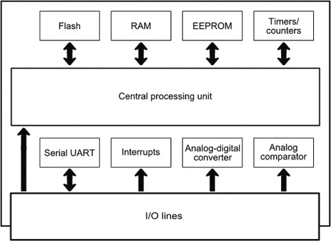
Figure 35-4 Basic block diagram of the Atmel AVR ATmega328 microcontroller. The central processing unit (CPU) forms the core of the controller. Additional built-in hardware provides special functions, such as timers, an analog comparator, and an analog-to-digital converter.
![]() Programmable full-duplex serial port. Serial data is a common means of communication with a microcontroller, not only for programming it, but also for the MCU to communicate with other devices.
Programmable full-duplex serial port. Serial data is a common means of communication with a microcontroller, not only for programming it, but also for the MCU to communicate with other devices.
PIN FUNCTIONS
Being integrated circuits, the pins on microcontrollers serve as the means to power the chip, as well as get signals in and out of the device. Figure 35-5 shows the pinout diagram of the Atmel AVR ATmega328 microcontroller and the functions of each pin. The labels for the pins have little meaning without the datasheet for the controller, but this diagram gives you an idea of the general layout you’ll encounter.
As with many microcontrollers, the pins are identified with a default function, as well as alternative functions, if any. The alternative functions are shown here in parentheses. For example, pin 1 serves as the reset button for the chip. Press it and the microcontroller restarts its programming.
But pin 1 can also serve additional functions, if a reset isn’t needed. It can be used as just another digital input/output pin (belonging, according to the diagram, to the Port C group; ports are convenient collections of I/O pins).
MORE ON PROGRAM AND DATA STORAGE
At first glance, it looks like microcontrollers have somewhat limited memory space for programs. The typical low-cost microcontroller may have only a few thousand bytes (yes, bytes, not megabytes) of program storage. While this may seem terribly confining, in reality most microcontrollers are programmed to do single or well-defined jobs. These jobs may not require more than a few dozen lines of program code.
More elaborate microcontrollers may handle more program storage—8K or 32K are not uncommon, and a few can support well over a megabyte. Keep the program storage limits in mind when you’re planning which brain to get for your robot. A single type of microcontroller is often available in slightly different versions; each version may accommodate a different amount of program data.
Data storage may seem even more restricted. The typical microcontroller may only provide 1K or 2K of RAM for data (EEPROM space, if provided, is even less). But again, most microcontroller applications make efficient use of data space. As long as you follow good coding practice, you should seldom run out of data storage space.

Figure 35-5 Pinout diagram of the ATmega328 microcontroller, showing the pin numbers (from 1 to 28), plus labels for the functions of each pin. Most pins have alternative functions, shown in parentheses.
ERASING AND STARTING OVER
As noted, most microcontrollers are meant to be programmed over and over again. Each time you download a program to it, the old one is erased, and the new one takes its place. The most common program storage used in modern microcontroller is flash, the same as that used in USB thumb drives, or the CompactFlash cards in a digital camera.
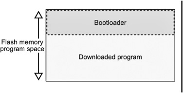
There is an exception to completely erasing the flash memory each time you download a new program. Some microcontrollers are set up to allow a special “bootloader” area in flash, which contains special setup code to make it easier to reprogram the chip without having to pull it out of its circuit.
IN-FIELD PROGRAMMING (AND REPROGRAMMING)
A key benefit of microcontrollers with flash memory is that they can be programmed and reprogrammed “in circuit”—that is, while the chip is still plugged into whatever circuit board home it’s living in.
This has enormous potential for use in your programmable robot. With in-field programming there is no need to remove the microcontroller chip from its circuit in your robot to reprogram it. Instead, you merely connect a cable from your PC and download the new program. Of course, this requires that the microcontroller have an onboard connector so it can be attached to your PC cable.
ONE-TIME PROGRAMMABLE
Less costly microcontrollers are made to be programmed only once, and are intended for permanent installations. These one-time programmable (OTP) microcontrollers are popular in consumer goods and automotive applications.
For robotics applications, the OTP is useful for dedicated processes, such as controlling servos or triggering and detecting a sonar ping from an ultrasonic distance measurement system. You’ll find a number of the ready-made hobby robotic solutions on the market today that have, at their heart, an OTP microcontroller. The microcontroller takes the place of more complex circuitry that uses individual integrated circuits.
Microcontroller Programmers
All microcontrollers need to be programmed. The complexity of the programming setup depends on the architecture of the microcontroller. For example, the PICAXE and BASIC Stamp controllers can be connected to a PC using a simple cable—typically just a serial cable that has the usual DB-9 connector on one end (for connection to the PC) and header pins on the other (for connection to the controller).
Chip-only microcontrollers without a built-in language need a programmer, a physical device that provides all the necessary power and signal connections to the chip. The programmer connects to your PC via a serial or (more often) USB cable. Most programmers are designed for a certain brand of microcontroller—the Atmel AVR line or the PICMicro.

Figure 35-6 Microcontroller programmer, with sockets to accept controllers of different sizes. The programmer connects to a host computer via a cable.
Figure 35-6 shows an STK500 programmer made for AVR microcontrollers. Like many of its kind, the STK500 has several sockets of different sizes for accepting the different members of the microcontroller family. To use, you plug an “empty” (unprogrammed) chip into its corresponding socket, connect the programmer to your PC, and download your application.
Some programmers are combined with development systems, which provide numerous standard accessories onboard. These allow you to design fully operational microcontroller solutions, without having to create elaborate breadboards or construct custom circuits. Everything (or nearly so) is already included in the development system.
All about Microcontroller Speed
If you have a personal computer, you probably know that its microprocessor runs at a certain speed. Older PCs were rated in megahertz (millions of cycles per second); the latest models operate in the gigahertz (billions of cycles per second) range.
Likewise, microcontrollers operate at set speeds. These speeds are rather low for a modern computational device—most MCUs operate at 4 MHz to 40 MHz. That’s along the lines of the first IBM PCs that came out in the early 1980s!
But again, the nature of microcontrollers doesn’t require superspeeds. For one thing, many microcontrollers are more efficient in how they execute their program code. Most microcontrollers can execute a single programming instruction in just one cycle of the clock. A controller operating at 20 MHz can therefore process about 20 million programming instructions each second.
Yet sometimes the speed of a microcontroller is not enough for the task you want to give it. Processing full-motion video is a good example. You probably wouldn’t want to task your 4-MHz MCU with reading a frame of video (there are 25 or 30 frames each second) and analyzing each pixel for motion.