
Chapter 34
An Overview of Robot “Brains”
“Brain, brain, what is brain?” If you’re a Trekker, you know this is a line from one of the original Star Trek episodes of the 1960s, entitled “Spock’s Brain.” The quality of the story notwithstanding, the episode was about how Spock’s brain was surgically removed by a race of women who needed it to run their air-conditioning system. Dr. McCoy rigged up a gizmo to operate Spock’s brainless body by remote control.
“Brains” are what differentiate robots from simple automated machines—brainless Spocks who might as easily crash into walls as move in a straight line. The brains of a robot process outside influences, such as sonar sensors or bumper switches; then, based on their programming or wiring, they determine the proper course of action.
A computer in one form or another is the most common brain found on a robot. A robot control computer is seldom like the PC on your desk, though robots can certainly be operated by most any personal computer. And, of course, not all robot brains are computerized. A simple assortment of electronic components—a few transistors, resistors, and capacitors—are all that’s really needed to make a rather intelligent robot. Hey, it worked for Mr. Spock!
In this chapter we’ll review the different kinds of “brains” found on the typical amateur robot, including the latest microcontrollers—computers that are specially made to interact with (control) hardware. Endowing your robot with smarts is a big topic, so additional material is provided in Chapters 35 through 41, including individual discussions on using several popular microcontrollers, such as the Arduino and PICAXE.
Brains for the Brawn
Let’s start by reviewing the six principal ways to endow your Scarecrow robot with a brain—no Wizard of Oz required here; it’s all done with bits of wire and other parts.
Human control: Some very basic robots are controlled by human interaction. Switches on the robot, or in a wired control box, let you operate your creation by hand. Human control is an ideal way to learn about how robots operate. Examples include robotic arms, where you control the movement of various arm joints.
Discrete components: In years past, the typical robot brains used basic electronic components like the resistor and transistor (and even before that, tubes!). Now, with inexpensive microcontrollers, these kinds of circuits aren’t seeing as much use, but they’re still ideal for simple robots with simple jobs to do.
Microcontrollers: A microcontroller is computer-on-a-chip, with a “thinking” processing unit, memory, and means to connect with the outside world. Microcontrollers are the ideal form of robot brain because they’re simple, cheap, and easy to use. You program them from your personal computer.
Onboard computers: Some bots need more computational power than microcontrollers can provide. Most any computer that doesn’t weigh more than you do and require massive amounts of power to operate is a candidate for use as a robot brain. Laptops, netbooks, and computers with compact main boards are among the best choices as Robo Brainiac.
Remote computers: While the typical amateur bot is self-contained, there’s no technical reason it can’t be controlled by a computer located someplace else. This is typical of “teleoperated” robots, like those used by the military or in police bomb disposal. The computer is connected to the robot via wire, radio waves, or some other means.
Smart phones, tablets, and PDAs: Some consumer gadgets like mobile phones and personal data assistants can be pressed into service as robot controllers. The ideal device has a USB or other standard communications interface and an open architecture to allow you to write programs for it. One possibility: the mobile phones that use the Android operating system.
Igor, Pull the Switch!
I’m a believer in starting out simple. And it doesn’t get any simpler than using manually operated switches to control a bot. While this is not a true “robot” in the formal sense of the word, it’s a useful way to discover how robots work. By manually operating the robot with your own hands, you learn how it has to be done via fully electronic control.
Adding switches to operate a basic robot is easy. I prefer putting the switches and battery power in the same handheld remote—fewer wires that way. The basic RBB Bot in the My First Robot lessons (see the RBB Online Support site) uses a piece of picture frame mat board to hold two switches and a standard battery holder. You can get fancier and build a control box out of a real box. There are a number of project boxes just the right size for use as a switch-operated remote.
In operation, the switches are wired so you can start and stop the motors and control their direction. By changing the direction of one or both motors, you learn how to maneuver the robot around a room.
Brains from Discrete Components
In the world of electronics, discrete components are parts like transistors, resistors, and basic-building-block integrated circuits. These components, used in some clever combination, can produce a working, thinking brain of a basic robot.

Figure 34-1 A few parts from basic electronic components form a workable robotic brain. Depending on how the parts are configured, the robot can display different “behaviors.” In one variation of this light-detection circuit, the rebot responds to light; in the other variation, the robot responds to darkness.
Figure 34-1 shows a common form of robot brain made from from simple parts. Wired one way, this brain makes the robot reverse direction when it sees a bright light. The circuit is simple, as is the functionality of the robot: light shining on the photodetector might turn on a relay or actuate some other circuit.
Variations of this circuit could make the robot stop when it sees a bright light. By using two sensors, each connected to separate motors, you can make the robot follow a bright light source as it moves. By simply reversing the sensor connections to the motors, you can make the robot behave in the opposite manner: it steers away from the light source, instead of driving toward it.
You could add additional simple circuitry to extend the functionality of robots that use discrete components for brains. For instance, you could use an LM555 timer as a time delay: trigger the timer and it runs for 5 or 6 seconds, then stops. You could wire the LM555 to a relay so it applies juice only for a specific amount of time. (This is the basic function of the enhanced RBB Bot in the My First Robot lessons.) In a two-motor robot, and using two LM555 timers with different time delays, your robot can be made to steer around things.
Programmed Brains
Perhaps the biggest downside of making robot brains from discrete components is that because the brains are hardwired as circuitry, changing the behavior of the machine requires considerable work. You need to either change the wires around or add and remove components. Using a solderless breadboard (see Chapter 32) makes it easier to try out different designs simply by plugging in components. But this soon gets tiresome and can lead to errors because parts can work loose from the board.
You can “rewire” a robot controlled by a computer simply by changing the software running on the computer. For example, if your robot has two light sensors and two motors, you don’t need to do much more than change a few lines of programming code to make the robot come toward a light source rather than move away from it.
TYPES OF PROGRAMMABLE GRAY MATTER
An almost endless variety of computers and computer-like devices can be used as a robot brain. The five most common are:
![]() Microcontroller. A microcontroller is programmed in either assembly language or a high-level language such as Basic or C. Figure 34-2 shows a Parallax BOE-Bot robot kit, which is driven by a BASIC Stamp microcontroller. See Chapter 35, “Understanding Microcontrollers,” for more information on this topic.
Microcontroller. A microcontroller is programmed in either assembly language or a high-level language such as Basic or C. Figure 34-2 shows a Parallax BOE-Bot robot kit, which is driven by a BASIC Stamp microcontroller. See Chapter 35, “Understanding Microcontrollers,” for more information on this topic.

Figure 34-2 A programmable controller uses software rather than specific wiring to determine how the robot reacts. This BOE-Bot robot kit from Parallax uses the BASIC Stamp 2 microcontroller, which reads the value of sensors and applies power to the robot’s two motors accordingly. (Photo courtesy Parallax Inc.)
![]() Single-board computer. This is also programmed but it generally offers more processing power than a microcontroller. It is more like a miniature personal computer. For example, you can get a single-board computer based on the Intel Pentium and have it run versions of Windows or Linux.
Single-board computer. This is also programmed but it generally offers more processing power than a microcontroller. It is more like a miniature personal computer. For example, you can get a single-board computer based on the Intel Pentium and have it run versions of Windows or Linux.
![]() Personal computer. Old-school examples include the IBM PC and compatibles, but as these machines get older, they’re harder to find. Plus they consume lots of power because their electronics weren’t as efficient as they are today. Better choices are laptops and net-book computers.
Personal computer. Old-school examples include the IBM PC and compatibles, but as these machines get older, they’re harder to find. Plus they consume lots of power because their electronics weren’t as efficient as they are today. Better choices are laptops and net-book computers.
![]() Motherboard for a compact personal computer. The main board, or motherboard, of a Mini-ITX PC measures under 7″ square, yet it can run any modern operating system (OS) designed for the Intel processors, including Windows and Linux. The idea is that, rather than using a whole computer on your robot, you can attach just the motherboard.
Motherboard for a compact personal computer. The main board, or motherboard, of a Mini-ITX PC measures under 7″ square, yet it can run any modern operating system (OS) designed for the Intel processors, including Windows and Linux. The idea is that, rather than using a whole computer on your robot, you can attach just the motherboard.
![]() Smartphone, tablets, and personal data assistants. If you already have the processing power in a device you use every day, like your mobile phone, why not use it to make a robot? That’s the idea behind powering bots using personal consumer electronics. While great in theory, the practicality of pulling it off depends on the architecture of the device. Some products are more amenable for use as robot electronics than others.
Smartphone, tablets, and personal data assistants. If you already have the processing power in a device you use every day, like your mobile phone, why not use it to make a robot? That’s the idea behind powering bots using personal consumer electronics. While great in theory, the practicality of pulling it off depends on the architecture of the device. Some products are more amenable for use as robot electronics than others.
As noted, microcontrollers are covered in their own chapter; let’s take a closer look at the other options.
SINGLE-BOARD COMPUTERS
Single-board computers (SBCs) are a lot like “junior PCs” but on a single circuit board. While there are some that can run versions of Windows (typically Windows CE or the embedded version of Windows), many are engineered for an operating system that consumes less disk and memory space, such as old-fashioned DOS or Linux.
SBCs are full-blown computers in every way, except that all the necessary components are on one board. Because of their design, SBCs can support megabytes, and even gigabytes, of program and data storage (most microcontrollers are limited to kilobytes of storage space). Whether you need a lot of storage depends on your application, but it’s nice to know the SBC can support it if you do.

If your SBC doesn’t come with an operating system, you need to provide one. DOS is a good all-around choice for robots that don’t need the bells and whistles of Windows. Microsoft no longer sells its once venerable MS-DOS, which at one time was packaged with almost all PCs. There are many free open-source alternatives, such as FreeDOS and DR-DOS, available for download from the Web.
You can also sometimes find surplus 3-1/2″ diskettes of MS-DOS 5 and 6 in the dusty-shelf section of old surplus stores. You need a 3-1/2″ disk drive to read the content of the disks and transfer it to the solid-state memory used by most SBCs.
SBC Form Factors
Single-board computers come in a variety of shapes and forms. A standard form factor supported by many manufacturers is PC/104, which measures about 4″ square. PC/104 gets its name from “Personal Computer” and the number of pins (104) used to connect two or more PC/104-compatible boards together.
SBC Kits
To handle different kinds of jobs, SBCs are available in larger or smaller sizes than the 4″ by 4″ PC/104. And while most SBCs are available in ready-made form, they are also popular as kits. For example, the HandyBoard, designed by instructors at MIT, is a single-board computer based on the Motorola 68HC11 microcontroller. It is available already assembled or as a kit.
PERSONAL COMPUTERS
Having your personal computer control your robot is an admirable use of available resources, but it’s not always practical if you’re planning on mounting the thing on top of good old Tobor (that’s robot spelled backward). The old-style desktop PC is simply too heavy, bulky, and power hungry to be an effective source of brains for your bot.
There are two ways to use a PC to control your robot:
![]() Brains on bot. Mount the computer on the robot. For a laptop, you can rely on its internal battery. But for a desktop PC meant to be plugged into the wall, you’ll need to either run the computer using a large 12-volt battery and car power inverter or retrofit the computer with a power supply that can be juiced directly from the battery.
Brains on bot. Mount the computer on the robot. For a laptop, you can rely on its internal battery. But for a desktop PC meant to be plugged into the wall, you’ll need to either run the computer using a large 12-volt battery and car power inverter or retrofit the computer with a power supply that can be juiced directly from the battery.
![]() Brains off bot. You use any kind of computer and link it to your robot via wires, radio frequency (RF) link, or optical link. This is common practice when using tabletop robotic arms; since the arm doesn’t scoot around the floor, you can place it beside your PC and tether the two via wire. A USB connection is a favorite tethering technology—not to mention inexpensive and easy to use. There’s also Bluetooth, Zigbee, and other types of radio links if you don’t want the wires.
Brains off bot. You use any kind of computer and link it to your robot via wires, radio frequency (RF) link, or optical link. This is common practice when using tabletop robotic arms; since the arm doesn’t scoot around the floor, you can place it beside your PC and tether the two via wire. A USB connection is a favorite tethering technology—not to mention inexpensive and easy to use. There’s also Bluetooth, Zigbee, and other types of radio links if you don’t want the wires.
Using an On-Bot PC
You have quite a few options for mounting a PC on your robot.
Laptops and Netbooks
The ideal computer for onboard brains is a laptop running your favorite operating OS. Laptops carry their own rechargeable batteries and are made to be lightweight. You can use your regular laptop or else purchase one specially for your bot. You don’t need a new laptop; find one used and save a few bucks.
A netbook is an even smaller lightweight alternative. Many run a version of Windows or else a proprietary operating system. Be careful with netbooks with a proprietary OS, as you may not be able to write programs for use with your robot. Like laptop PCs, netbooks are battery powered.
Mini-ITX PC
And yet another option is the Mini-ITX PC, so called because it uses a mini-ITX motherboard. Mini-ITX is not a brand but technically a “form factor” and design architecture. The board measures 6.7″ × 6.7″, and many versions don’t need a fan for cooling.
If using a Mini-ITX PC in a case designed for AC operation, you can still give it power on your mobile robot by using a 12-volt battery and car power inverter. The inverter takes the 12 volts DC from the battery and generates 110 volts AC for the computer.
While this sounds like a roundabout way to go, it’s not quite as inefficient as it seems. Still, you need a strong battery to power the computer for any length of time. A 12-volt motorcycle battery is one option.
Mini-ITX Motherboard
While plopping a whole Mini-ITX PC on top of your robot is a quick and convenient way to endow it with smarts, the case and power supply add unnecessary weight that reduce battery life. One approach is to pull out the motherboard from the PC (Figure 34-3) and mount it directly onto your bot.
The design of mini-ITX motherboards incorporates all of the really important jacks and sockets directly on the board. You seldom need to add accessory boards to complete the system—jacks are provided for mouse, keyboard, monitor, USB, sound out, microphone in, and many others.
DC-to-DC power supply modules let you operate the motherboard directly from a 12-volt battery; no inverter is necessary. These modules are very small, highly efficient (90 percent and higher), and relatively inexpensive. You can match the DC-to-DC module with the power consumption of your motherboard. You can save money if the mini-ITX board consumes only 90 or 100 watts, as this means you can use a cheaper DC-to-DC power supply module.
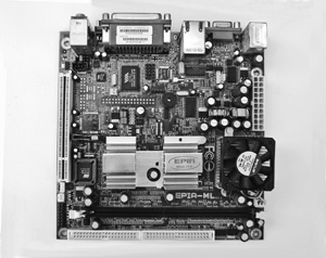
Figure 34-3 Mini-ITX motherboard, able to run Windows, Linux, and many other modern operating systems. Its small size and miserly power requirements make the board a perfect contender for use in a medium- to large-size robot.
Communications Interconnectivity
Not long ago, computers came with a variety of external ports for connecting things to them: parallel ports for printers, serial ports for phone modems, and game ports for joysticks—among others. All these provided fairly easy ways to connect the computer to robot hardware.
Today, the typical PC lacks all three. Instead, it relies almost entirely on the all-purpose USB port. That’s okay, as USB is a flexible system and cables for it are inexpensive. But it also means you need to get an adapter to convert the fairly sophisticated USB signals from your PC to a form you can readily use with your robot. These adapters change USB ports into parallel or serial ports. They’re commonly available from online electronics parts outlets; refer to Appendix B, “Internet Parts Sources,” for a list of popular Web-based stores.
Data Storage
Whatever your type of PC, you need some means to store your programs and other important data. Notebook and netbook computers already have this solved; they come with their own compact drives, either hard disk or solid state.
If using a mini-ITX motherboard by itself, you can pick from a variety of mass data storage options:
![]() Flash drive. This appears to the mini-ITX as a standard hard drive, but it actually contains no moving parts. It’s all flash memory in there. Data capacities are somewhat low when compared to traditional hard drives, and the cost is more. But flash drives are quiet and weigh next to nothing, and they aren’t damaged if the robot suddenly falls over.
Flash drive. This appears to the mini-ITX as a standard hard drive, but it actually contains no moving parts. It’s all flash memory in there. Data capacities are somewhat low when compared to traditional hard drives, and the cost is more. But flash drives are quiet and weigh next to nothing, and they aren’t damaged if the robot suddenly falls over.
![]() Small-profile (2.5″) hard drive. When you need lots of data space, nothing beats a hard drive. These are compact models made to take up little room. Because they contain a spinning disk drive, you must be careful when using them on mobile robots.
Small-profile (2.5″) hard drive. When you need lots of data space, nothing beats a hard drive. These are compact models made to take up little room. Because they contain a spinning disk drive, you must be careful when using them on mobile robots.
![]() USB hard drive or thumbdrive. Via the USB port on the motherboard you can connect any of a number of mass media drives, including compact hard drives and small thumb drives. When selecting a compact hard drive, get one that derives its power from the USB port itself. You don’t want the kind that needs to be plugged into a wall outlet.
USB hard drive or thumbdrive. Via the USB port on the motherboard you can connect any of a number of mass media drives, including compact hard drives and small thumb drives. When selecting a compact hard drive, get one that derives its power from the USB port itself. You don’t want the kind that needs to be plugged into a wall outlet.
In order to use a USB hard drive or flash drive, you must be sure the motherboard can boot (start) from the USB drive. Most can, but you’ll want to make sure before you purchase any new board.
Using an Off-Bot PC
Tabletop and teleoperated robots can be controlled with a separate PC. An example of a tabletop robot is a stationary arm. These can readily be connected to the host computer via a USB cable. Unless the arm has its own USB jack on it, you’ll need a USB-to-serial or USB-to-parallel adapter.
Teleoperated robots can also use wireless communication. There are literally dozens of off-the-shelf standardized solutions for connecting devices (including robots) through the airwaves, including Bluetooth, 802.15.4 Zigbee, and 802.11 Wi-Fi. From your desktop or laptop PC, you connect to a wireless transceiver through a standard USB port. That transceiver communicates with another transceiver on your robot. This second transceiver can then control motors, operate a remote camera, even send back video signals to your computer.
If going this route, you can choose between half-duplex and full-duplex communications. With half-duplex, only one side can talk at a time. For example, you can command your robot, but it can’t send back information at the same time. For greatest flexibility, you want full-duplex communications. You’ll be able to send and receive simultaneously. If the data speed is fast enough, you can readily command the robot to move around a room and have it beam back pictures via its video camera.
Data speeds for wireless communications depend on the distance between sender and receiver, and on the technology. Wi-Fi is faster than Bluetooth, which is (usually) faster than Zigbee. At longer distances, data speeds are reduced to avoid errors. Most RF data communications systems can be used 50 to 100 feet from source to target. For infrared, the distance is much less.
SMARTPHONES, TABLETS, AND PDAS
Rounding out the discussion of brains for your robot are smartphones, computer tablets, and personal data assistants (PDAs). To be useful as a robot brain, the device:
![]() Should be user programmable. A PDA or smartphone that won’t let you add your own programs is useless as a robot controller.
Should be user programmable. A PDA or smartphone that won’t let you add your own programs is useless as a robot controller.
![]() Provides some kind of communications link between itself and the robot electronics. On many devices this is through Bluetooth, but on others you need to use USB, if available.
Provides some kind of communications link between itself and the robot electronics. On many devices this is through Bluetooth, but on others you need to use USB, if available.
Microsoft, Google, and several others tout smartphones that allow you to write and upload your own programs. Example: Microsoft smartphones run Windows Mobile, a version of Windows tailor-made for use on small devices. You can write programs using Microsoft Visual Basic. Net or C#.Net (both free from Microsoft) for use on the phone. Phones that use the open-source Android operating system developed by Google offer similar programming features.
The disadvantage of these devices is the limitations inherent in their design as products that are made for something other than robot control. Their programming tools are not designed to control real-world devices, so developing a robot application tends to involve a lot of compromises.
Of Inputs and Outputs
The architecture of robots requires inputs—things like sensors and bumper switches. And then there’s outputs, such as motor control, light, and sound. The basic input and output of a computer or microcontroller is a two-state voltage level (that is, off and on), which usually equates to 0 and 5 volts. For example, to place an output of a computer or microcontroller to HIGH, the voltage on that output is placed, under software control, to 5 volts.
In programming, LOW is equivalent to off, or binary 0. HIGH is equivalent to on, or binary 1. The LOWs and HIGHs are bits. Read more about basic programming for robotics in Chapter 36, “Programming Concepts: The Fundamentals.”
Inputs and outputs are colloquially referred to as I/O. In addition to standard LOW/HIGH inputs and outputs, there are several other forms of I/O found on single-board computers and microcontrollers. The more common are listed in the following sections, organized by type. Several of these are discussed in more detail in Chapter 40, “Interfacing Hardware with Your Microcontroller or Computer.”
SERIAL COMMUNICATIONS
Robot subsystems need a way to talk to one another. This is often done with a serial communications interface. With serial communications, data is sent one bit at a time. Sounds slow and tedious, but it’s really not. The communications link needs just a few wires and can exchange data at speeds easily exceeding tens of thousands of bits per second.
The most common types of serial communications include the following:
I2C (inter-integrated circuit): also shown as I2C. This is a two-wire serial network scheme that allows integrated circuits to communicate with one another. With I2C you can install two or more microcontrollers in a robot and have them talk to one another.
SPI (serial peripheral interface): This is a popular serial communications standard used by many electronic devices. SPI is most often used to interface with microcontrollers or microprocessor support electronics.
Synchronous serial port: This is a generic term for most any serial data link where information is transmitted one bit at a time, using (at least) two wires. One wire contains the transmitted data, and the other wire contains a clock signal. The term synchronous means the clock serves as a timing reference for the transmitted data. This is different from asynchronous serial communication (discussed next), which does not use a separate clock signal.
UART (universal asynchronous receiver transmitter): UARTs are more common in desktop computers, but they have applications in microcontrollers as well. Asynchronous means there’s no separate synchronizing system for the data. Instead, the data itself is embedded with special bits (called start and stop bits) to ensure proper communication.
MIDI (Musical Instrument Digital Interface): MIDI is a fairly old standard that is found on most every digital keyboard and electronic music device. While you can use MIDI just for its serial communications protocol, you can also adapt it for robotics. Though it’s beyond the scope of this book, it’s possible—just as an example—to control a robot by playing notes on an electronic keyboard.
Microwire: This is a serial communications scheme used in National Semiconductor products, which is popular for use with the PICMicro line of microcontrollers from Microchip Technologies. It’s similar to SPI. Most Microwire-compatible components are used for interfacing with microcontrollers.
PARALLEL COMMUNICATION
Parallel data communication is more straightforward than serial, but it’s not necessarily easier to implement. With parallel data, you combine the values of two or more I/O lines of the computer or microcontroller. With eight I/O lines you can communicate 256 different messages; this is because there are 256 different ways to set the two possible states (0 and 1) of the lines.
An example of using parallel communication is displaying text on a liquid-crystal display (LCD) panel. While you can purchase an LCD panel that connects to your microcontroller via serial data, these are much more expensive. With just six I/O lines you can directly control a run-of-the-mill LCD panel.
On most microcontrollers, there is a critical shortage of I/O pins, so using parallel communications for everything uses up valuable data lines. To circumvent this, you can use simple and inexpensive electronics to convert serial data to parallel. You can also do the inverse. See Chapter 40, “Interfacing Hardware with Your Microcontroller or Computer,” for more details on using serial-to-parallel and parallel-to-serial conversion.
ANALOG AND DIGITAL CONVERSION
The command circuitry of your robot is digital; the world around us is analog (see Figure 34-4). Sometimes the two need to be mixed and matched, and that’s the purpose of conversion. There are two principal types of data conversion:
ADC: Analog-to-digital conversion transforms analog voltage charges to binary (digital). ADCs can be outboard, contained in a single integrated circuit, or included as part of a microcontroller. Multiple inputs on an ADC chip allow a single IC to be used with several signal sources.
DAC: Digital-to-analog conversion transforms binary (digital) signals to analog voltage levels. DACs are not as commonly employed in robots, but that doesn’t mean you can’t be clever and think of a nifty way to use one.
PULSE AND FREQUENCY MANAGEMENT
Digital data are composed of electrical pulses, and these pulses may occur at a more or less even rate. Pulses and pulse rate (or frequency) are commonly used in robotics for such things as reading the value of sensors or controlling the speed of motors. The three major types of pulse and frequency management are:
Input capture: This is an input to a timer that determines the frequency (number of times per second) of an incoming digital signal. With this information, for example, a robot can differentiate between inputs, such as two different locator beacons in a room. Input capture is similar in concept to a tunable radio.
PMW: Pulse width modulation is a digital output where pulses have a varying duty cycle (that is, the “on” time for the waveform is longer or shorter than the “off” time). PMW is often used to control the speed of a DC motor.
Pulse accumulator: This is an automatic counter that counts the number of pulses received on an input over a period of time. The pulse accumulator is part of the architecture of the microcontroller and can be programmed to operate autonomously. This means the accumulator can be collecting data even when the rest of the microcontroller is busy doing something else.
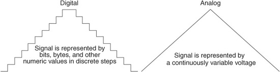
Figure 34-4 Comparison of digital and analog signals. Digital signals are in discrete steps and equate to numeric values. Analog signals are continuously variable.