
Chapter 37
Using the Arduino
Microcontrollers are now so commonplace that you have your pick of hundreds of makes and models, from the supersimple to the confoundedly complex. Somewhere in the middle is the Arduino, a small and affordable microcontroller development board that’s fast becoming something of a superstar.
What’s made the Arduino a darling of geeks the world over is this: both its hardware design and its software are open source. That means others are able to take the best ideas and improve on them, all without paying licensing fees. This has created something of a cottage industry of fans and third-party support.
In this chapter you’ll read about what the Arduino is and how to apply it to your robotics chores. Be sure to see the chapters in Part 8 for numerous working examples of using the Arduino in real-world applications, and also check out the bonus programming examples on the RBB Online Support site. See Appendix A for details.
Arduino under the Hood
First introduced in 2005, the Arduino has gone through numerous iterations, revisions, and improvements. Figure 37-1 shows what might be called the main or core Arduino board design: it’s a printed circuit board that measures 2-1/8″ by 2-3/4″, containing an Atmel ATmega microcontroller chip running at 16 MHz, a power jack for a 2.1mm (center positive) barrel connector, and a USB Type B jack for hooking up to a host computer. Example models of this design include the Uno and Duemilanove.
A series of 28 female pin headers allow connection of external devices to the Arduino. The headers are separated into three groups: power, analog input, and digital input/output.
Of the 28 pins, 20 are devoted to input and output. There are 6 analog input pins, which can also serve as general-purpose digital I/O. The 14 digital input/output pins include 6 that can be used to generate PWM (pulse width modulated) signals, useful for such things as controlling the speed of motors. All I/O pins can be used as digital outputs and can sink or source up to 40 milliamps.
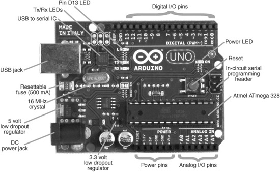
Figure 37-1 Points of interest on the Arduino board include the USB and power jacks, function and power LEDs, and rows of connection headers.
At the heart of the Arduino is an Atmel ATmega microcontroller. The exact version of chip depends on the version of the Arduino. For example, the older Diecimila used an Atmel ATmega168; later versions have used an ATmega328. The two chips are physically identical, but the ’328 offers more memory space.

Let me pause here to point out that the microcontroller chips used on the Arduino are not “empty.” They, in fact, come preloaded with a small bootloader program for use with the Arduino development editor, described later in this chapter. The bootloader assists in the download process.
Many Variations on a Theme
The core board design, like that in Figure 37-1, is perhaps the most common and popular of the Arduinos, but there are numerous other variations. Here are just some of the standardized Arduino boards you’ll encounter—note that versions and names may change over time:
![]() The Arduino BT and Fio are intended for wireless applications. The BT contains a Bluetooth module; the Fio has a built-in Zigbee radio.
The Arduino BT and Fio are intended for wireless applications. The BT contains a Bluetooth module; the Fio has a built-in Zigbee radio.
![]() The Nano is a compact stick-shaped board made for breadboard use. It has all the main features of the core boards (including built-in USB jack), but measures only 0.73″ × 1.7″.
The Nano is a compact stick-shaped board made for breadboard use. It has all the main features of the core boards (including built-in USB jack), but measures only 0.73″ × 1.7″.
![]() The Mini is even smaller, and is ideal for very small bots with limited space. The Mini lacks its own USB jack and requires the use of a USB adapter or serial TTL connection to the host PC for programming.
The Mini is even smaller, and is ideal for very small bots with limited space. The Mini lacks its own USB jack and requires the use of a USB adapter or serial TTL connection to the host PC for programming.
![]() The Mega2560 is based on a larger Atmel chip, and it offers over twice the number of analog and digital I/O lines. Memory and program space are larger, too.
The Mega2560 is based on a larger Atmel chip, and it offers over twice the number of analog and digital I/O lines. Memory and program space are larger, too.
Several Arduino resellers offer their own custom offshoots of the Arduino—these typically go by different names, such as Boarduino or Freeduino, to differentiate them from the original Arduino designs.
Some variations of the Arduino depart from the standard form factor of the core Arduino boards and are not designed for use with expansion shields, discussed later in this chapter. A good example is the LilyPad, a special Arduino layout engineered for making—among other things—wearable microcontroller projects. Think Borg implants, only more friendly looking. The flower-shaped LilyPad has a flat profile and can be sewn into fabric. It has connection points on the ends of its 22 petals.
Ready Expansion via Shields
The Arduino itself has no breadboard area, but it’s easy enough to connect any of the inputs or outputs to a small breadboard via wires. For an application like robotics, you’ll want to expand the Arduino I/O headers to make it easier to plug in things like motors, switches, and ultrasonic or infrared sensors.
One method is to use an add-on expansion board known as a shield. Shields stick directly on top of the core board and Mega designs. Pins on the underside of the shield insert directly into the Arduino’s I/O headers. Two popular expansion shields are the solderless breadboard shield (see Figure 37-2) and the proto shield; both provide prototyping areas for expanding your circuit designs.
Of course, you don’t absolutely need a shield to expand the Arduino. You can place a breadboard—solderless or otherwise—beside the Arduino and use ribbon cables or hookup wire to connect the two together.
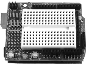
Figure 37-2 Expansion shield for the Arduino, offering a small solderless breadboard for experimenting. Use short jumper wires to connect the Arduino pins (top and bottom) to the contact points in the breadboard. (Photo courtesy Adafruit Industries.)
USB Connection and Power
To allow the easiest possible means of programming, all the core Arduino boards support USB. You need merely to connect a suitable USB cable between the Arduino and your computer. The necessary USB drivers are provided with the Arduino software. In most cases, installation of the drivers is not fully automatic, but the steps are straightforward, and the Arduino support pages provide a walk-through example.
The USB jack provides communications, both for downloading programs from your PC (discussed later), and for serial communications back to the PC. The USB link includes a 500-mA resettable fuse to guard against possible damage caused by a wayward Arduino to the USB ports on your PC. When plugged into a USB port, the Arduino takes its power from it. With USB 2.0, drive current is limited to 500 mA, depending on the port design.
Operating voltage of the Arduino circuitry is 5 volts, which is supplied either by the USB cable when it’s plugged into a USB port on your computer or by a built-in low-dropout linear voltage regulator when the board is powered externally. The regulator is intended to be powered by 7 to 12 vdc; a 9-volt battery is ideal. Anything higher than 12 volts is not recommended, as it could cause the regulator to overheat.
The Arduino is also equipped with a 3.3-volt low-dropout voltage regulator. Depending on the version of the Arduino board, the regulator is either built into the USB-to-serial chip or separate. In either case, maximum current output is rather low, on the order of 50 mA. The 3.3-volt regulator is good for powering small electronics that require the lower voltage. These include certain types of accelerometers and gyroscopes.
For robotics I think it’s best to power the Arduino from its own battery, and use different batteries for the motors. You can make your own 9-volt battery to 2.1mm barrel connector jumper cable or purchase one ready-made (see Figure 37-3).
Indicator LEDs are provided on the Arduino for testing and verification. One LED shows power; two other LEDs show serial transmit and receive activity, and should flash when the board is being programmed from your computer. A fourth LED is connected in parallel with digital I/O line 13 and serves as a simple way to test the Arduino and make sure it is working properly.

Figure 37-3 Ready-made cable for connecting a 9-volt battery to the Arduino 2.1mm power jack. (Photo courtesy Adafruit Industries.)
Arduino Pin Mapping
The Arduino uses its own nomenclature for its I/O pins, and the names and numbers of its pins don’t correlate to those on the ATmega microcontroller. This can cause some confusion if you’re already familiar with working with the bare ATmega chips.
Figure 37-4 shows the pinout diagram of the 28-pin ATmega328 microcontroller chip. The labels on the inside of the chip are the primary function names for each of the pins. The labels outside in parentheses are alternative uses, if any, for the pins.
Also shown in Figure 37-4 is pin mapping between the Arduino and the ATmega328. It’s important to remember that the pin numbers are not the same between the two: pin 12 on the ATmega328 is actually mapped to digital pin D6 on the Arduino, for example. Pin mapping is not something you need to worry about in typical Arduino programming, but it’s nice to know what leads to where.
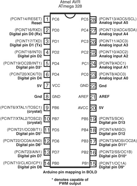
Figure 37-4 Pinout diagram of the Atmel ATmega328 chip, with the pin mapping to the Arduino I/O lines.
Programming the Arduino
Microcontrollers depend on a host computer for developing and compiling programs. The software used on the host computer is known as an integrated development environment, or IDE. The Arduino language is based on good old-fashioned C. If you are unfamiliar with this language, don’t worry; it’s not hard to learn, and the Arduino IDE provides some feedback when you make mistakes in your programs.
To get started with programming the Arduino using its IDE, first go to www.arduino.cc, and then click on the Download tab. Find the platform link (PC, Mac, Linux) for your computer, and download the installation file. Step-by-step instructions are provided in the Getting Started section of the Arduino Web site. Be sure to read through the entire set of instructions.
Once installation is complete, you’re ready to try out your Arduino. Start by connecting the board to your PC via a USB cable. If this is the first time you’ve used an Arduino on your PC, you must install the USB communications drivers, as detailed in the Getting Started guide.
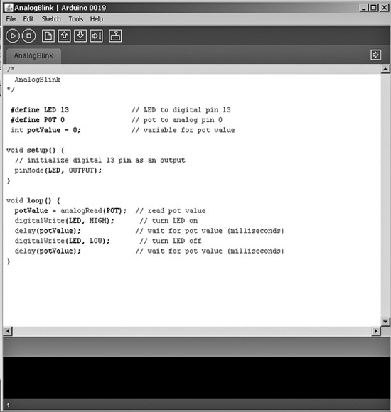
Figure 37-5 The Arduino integrated development environment (IDE) provides a centralized place to write, compile, and download programs to the Arduino board.
USING THE ARDUINO IDE: THE BASICS
Using the Arduino programming environment is simple. First-time use of the environment requires you to specify the Arduino board you are using and, as necessary, the serial port that is connected to the board (the Arduino’s USB connection looks like a serial port to your computer). You may then open an existing example program and download it to your board. Or you may write your own program in the IDE editor. Figure 37-5 shows the Arduino IDE with a short sketch in the main window.
The next step is to compile the program—called “sketches” in Arduino parlance. This prepares the code for downloading to the Arduino. At the bottom of the text editor is a status window, which shows you the progress of compiling. If the program was successfully compiled, it can then be downloaded to the Arduino, where it will automatically run once the download is complete.
A WORD ABOUT IDE VERSIONS
The Arduino IDE and the standard programming statements and libraries often undergo changes with each new version. The Servo library discussed later in this chapter was introduced in version 0017 of the Arduino IDE. If you already have an installed version of the IDE and it’s old, you’ll want to fetch the newest version. You can keep multiple versions of the Arduino IDE on your computer and even switch between them as needed—though that should seldom be required.
All of the programming examples in this book require version 0017 or later of the Arduino IDE, so make sure yours is compatible. The Arduino IDE is set to always check for the latest updates.
Programming for Robots
The Arduino supports the notion of libraries, code repositories that extend core programming functionality. Libraries let you reuse code without having to physically copy and paste it into all your programs. The standard Arduino software installation comes with several libraries you may use, and you can download others from the Arduino support pages, and from third-party Web sites that publish Arduino library code.
A good example of a library you’ll use with most any robot is Servo. This library allows you to connect one or more hobby R/C servos to the Arduino’s digital I/O pins. The Servo library comes with the standard Arduino installation package, so adding it to your sketch is as simple as choosing Sketch->Import Library->Servo.
Structurally, Arduino sketches are very straight forward and are pretty easy to read and understand. All Arduino sketches have at least two parts, named setup( ) and loop( ). These are called functions, and they appear in the sketch like this:
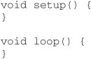
![]() The ( and ) parentheses are for any optional arguments (data to be used by the function) for use in the function. In the case of setup( ) and loop( ), there are no arguments, but the parentheses have to be there just the same.
The ( and ) parentheses are for any optional arguments (data to be used by the function) for use in the function. In the case of setup( ) and loop( ), there are no arguments, but the parentheses have to be there just the same.
![]() The { and } braces define the function itself. Code between the braces is construed as belonging to that function—the braces form what’s referred to as a code block. There’s no code shown here, so the braces are empty, but they have to be there.
The { and } braces define the function itself. Code between the braces is construed as belonging to that function—the braces form what’s referred to as a code block. There’s no code shown here, so the braces are empty, but they have to be there.
![]() The void in front of both function names tells the compiler that the function doesn’t return a value when it’s finished processing. Other functions you might use, or create yourself, may return a value when they are done. The value can be used in another part of the sketch.
The void in front of both function names tells the compiler that the function doesn’t return a value when it’s finished processing. Other functions you might use, or create yourself, may return a value when they are done. The value can be used in another part of the sketch.
![]() The setup( ) and loop( ) functions are required. Your program must have them, or the IDE will report an error when you compile the sketch. These are programming functions that do what their names suggest: setup( ) sets up the Arduino hardware, such as specifying which I/O lines you plan to use. The loop( ) function is repeated endlessly when the Arduino is operating.
The setup( ) and loop( ) functions are required. Your program must have them, or the IDE will report an error when you compile the sketch. These are programming functions that do what their names suggest: setup( ) sets up the Arduino hardware, such as specifying which I/O lines you plan to use. The loop( ) function is repeated endlessly when the Arduino is operating.
Many Arduino sketches also have a global declaration section at the top. Among other things, the declaration is where you put variables for use by the whole program—see the example in the next section. It’s also a common place to tell the IDE that you wish to use an external library, like Servo, to extend the base functionality of the Arduino.
USING VARIABLES
Arduino uses variables to store information while your sketch is running. The platform supports a number of data types for holding variables of different types and sizes. Among the most common are
![]() int—holds a signed (can be positive or negative) whole number (integer), where the value can be from −32,768 to 32,767.
int—holds a signed (can be positive or negative) whole number (integer), where the value can be from −32,768 to 32,767.
![]() unsigned int—holds an unsigned (positive only) number from 0 to 65,535.
unsigned int—holds an unsigned (positive only) number from 0 to 65,535.
![]() byte—holds an unsigned number from 0 to 255.
byte—holds an unsigned number from 0 to 255.
![]() boolean—holds a true or false value.
boolean—holds a true or false value.
![]() float—holds a floating-point value, where the digits to the right of the decimal can have up to 15 places.
float—holds a floating-point value, where the digits to the right of the decimal can have up to 15 places.
![]() String—holds text, usually meant for display on an LCD panel or transmission back to the PC as a message.
String—holds text, usually meant for display on an LCD panel or transmission back to the PC as a message.
To use a variable, you must first declare it. This may be done at the top of the sketch or anywhere within it. Where you declare a variable determines its scope: variables declared at the top of the sketch are global; that is, they can be used anywhere within the sketch. A variable declared inside a function can be used only within that function.
Declaring (or defining) a variable requires you to first specify its type. You then indicate its name, followed by an optional step of assigning a value to the variable just declared:
int myInt = 30;
declares an int variable named myInt, plus it assigns a value of 30 to it. This one line is equivalent to:
   int myInt;

   myInt = 30;
Names for variables must contain only letters and numbers or the underscore (_) character. The name can’t start with a number, and it can’t contain a space. Capitalization matters, so myInt is distinctly different from myint.
Many programmers prefer a consistent naming convention for their variables. This includes using consistent capitalization. The common practice today is called camelCase—low on the ends, high in the middle.
An exception to this is when using constants, variables whose contents are defined once and never changed. The common practice here is to use all uppercase characters, as in
const int POT = A0;
for a constant variable named POT.
USING ARDUINO PINS
The input/output pins of the Arduino are referenced by number. There are two numbering sequences: one for the analog pins and another for the digital pins.
![]() Analog pins are referenced as Ax, where x is a number. For example, to reference analog pin number 0, you’d use A0.
Analog pins are referenced as Ax, where x is a number. For example, to reference analog pin number 0, you’d use A0.
![]() Digital pins are referenced in sketches just by their numbers. (Additionally, within this book the digital pins are described as Dx—example: D13 or D9—to avoid any confusion about which pins to connect things to.)
Digital pins are referenced in sketches just by their numbers. (Additionally, within this book the digital pins are described as Dx—example: D13 or D9—to avoid any confusion about which pins to connect things to.)
In actual use, most of the Arduino programming statements are self-aware of the proper pins—analog or digital—to use. For example, when using the analogRead programming statement, which reads a voltage level at a pin, the compiler knows you’re talking about an analog pin, as the digital pins don’t support this feature.
By default, the digital pins are automatically considered as inputs, meaning they are set up to read a value, rather than set a value. At any point in a sketch you can inform the Arduino that you wish to use a pin as an output. The process is simple:
pinMode(PinNumber, Direction);
where PinNumber is the number of the pin you’d like to use, and direction is either INPUT or OUTPUT (these are predefined constants, by the way—that’s why they’re in uppercase). For example,
pinMode(13, OUTPUT);
makes pin D13 an output. Once made an output, it can do output-like things, such as light up an LED. Such an example follows later in this chapter.
Digital pins may be on or off, defined as 0 or LOW (off), or 1 or HIGH (on).
![]() Use digitalWrite when setting the value of a digital pin.
Use digitalWrite when setting the value of a digital pin.
![]() Use digitalRead when testing the value of a digital pin. You typically use a variable to store the value of the pin.
Use digitalRead when testing the value of a digital pin. You typically use a variable to store the value of the pin.
For example,
digitalWrite(13, HIGH);
turns pin D13 on (sets it HIGH).
myVar = digitalRead(13);
reads pin D13, and assigns its value (either LOW or HIGH) to the myVar variable.
EXPERIMENT BY DOING
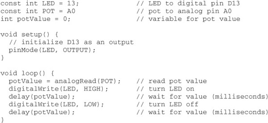
Program arduino_test.pde, shown below, demonstrates a few fundamental Arduino concepts useful in any robotics development, reading an analog sensor and providing visual feedback. I’ve taken one of the examples that come with the Arduino IDE and modified it slightly to conform to the style used throughout this book. It uses a 10 kΩ potentiometer to alter how fast Arduino’s built-in LED flashes.
Check out Figure 37-6 for a schematic of the circuit used for the program listing. The potentiometer is connected to the board as a common voltage divider. That way, the Arduino detects the value of the pot as a variable voltage from 0 volts (ground) to 5 volts.
![]()
Be careful with how you wire the potentiometer. Be sure the wiper is connected to pin A0, and the legs of the pot are connected to 5V and ground. If you accidentally connect the wiper to 5V or ground, you’ll create a dead short across the pot as you rotate it. The pot may burn out, and the Arduino will go into “fail-safe” protection mode by shutting down.
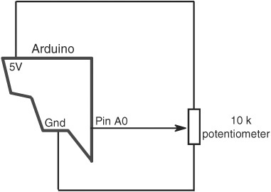
Figure 37-6 Schematic diagram for the arduino_test.pde sketch. The 10 kΩ pot is connected to the 5V and Gnd pins of the Arduino, as well as analog pin A0.

arduino_test.pde
Here’s how the program works:
The first two lines set variable constants, so hardware connected to the various I/O pins can be referred to by name, and not pin number. This is merely a convenience. The built-in LED is connected to pin D13, and the potentiometer—named POT in the program—is connected to analog pin A0.
Another variable is defined to hold the current value of the potentiometer, which will be a number from 0 to 1023. This number is derived from the Arduino’s integrated 10-bit analog-to-digital (ADC) converter, and it represents a voltage level from 0 volts to 5 volts.
The setup( ) section gets the Arduino hardware ready for the rest of the program. When first powered on, all the I/O lines are automatically defined as inputs. But the LED pin needs to be an output, so that distinction is defined here.
The loop( ) section is automatically started the moment the program has been downloaded to the Arduino. Looping continues until either the board is unplugged, the Reset button on the Arduino is pushed, or a new program is loaded into memory. The loop begins by reading the voltage on analog pin A0. The program then turns the LED on and waits for a period of time defined by the current position of the potentiometer before turning the LED off again.
The waiting period is in milliseconds (thousandths of a second), from 0 to 1023, the range of values from the Arduino’s ADC. Very fast delays of about 100 milliseconds or less will appear as a steady light.
Using Servos
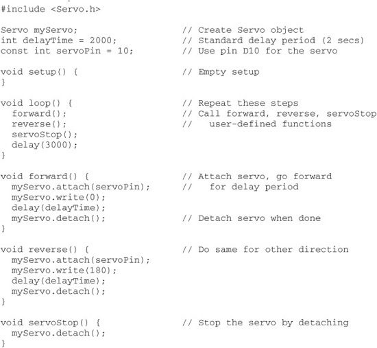
The following program swings the servo motor in one direction, then the other, briefly pausing in between. You can use either an unmodified or a modified (continuous rotation) servo to see the code in action. Refer to Figure 37-7 for a diagram on hooking up the servo. Use a standard-size (or smaller) analog servo; stay away from larger or digital servos, as they may draw too much current for the USB port on your computer to handle.
In the following example, text after the double slash // characters means a comment. It’s for us humans. During the compiling phase, comments are ignored, as they are not part of the functionality of the sketch.
basic_servo_test.pde

The first line, #include <Servo.h>, tells the IDE that you want to use the Servo library, which is a standard part of the Arduino IDE installation. (Other libraries may require a separate download, but they are used in the same way.) The name of the main Servo library file is Servo.h, so that is what’s provided here.
Servo is actually a name of a class; that’s how Arduino uses its libraries. With a class you can create multiple instances (copies) of an object without having to duplicate lots of code. Note that Servo is the name of the class to use, and myServo is the name I’ve given to the object just created.
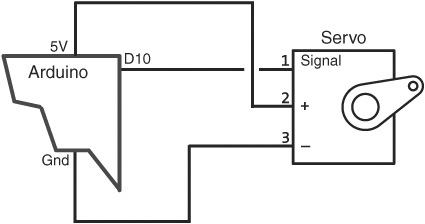
Figure 37-7 Connection diagram for testing servo functionality with the Arduino. Be absolutely sure of observing the correct polarity of the power and Ground connections to the servo.
The setup( ) function contains one statement, myServo.attach(10). Here’s what it all means:
![]() myServo is the name of the servo object that was defined earlier.
myServo is the name of the servo object that was defined earlier.
![]() attach is what’s known as a method. Methods are actions that you use to control the behavior of objects. In this case, attach tells the Arduino that you have physically connected the servo to digital pin D10, and you want to activate it. A period separates the object name and method—myServo.attach.
attach is what’s known as a method. Methods are actions that you use to control the behavior of objects. In this case, attach tells the Arduino that you have physically connected the servo to digital pin D10, and you want to activate it. A period separates the object name and method—myServo.attach.
Notice the ; (semicolon) at the end of the statement. It’s a statement terminator. This tells the compiler that the statement is complete and to go on to the next line.
The loop( ) function contains the part of the sketch that is repeated over and over again, until you download a new program or remove power from the Arduino.
![]() myServo.write(0) is another method using the myServo object. The write method instructs the servo to move all the way in one direction. When using a modified servo, this statement causes the motor to continually rotate in one direction.
myServo.write(0) is another method using the myServo object. The write method instructs the servo to move all the way in one direction. When using a modified servo, this statement causes the motor to continually rotate in one direction.
![]() delay(delayTime) tells the Arduino to wait the period specified earlier in the delayTime variable, which is 2000 milliseconds (2 seconds).
delay(delayTime) tells the Arduino to wait the period specified earlier in the delayTime variable, which is 2000 milliseconds (2 seconds).
![]() The two statements are repeated again, this time with myServo.write(180) to make the servo go in the other direction.
The two statements are repeated again, this time with myServo.write(180) to make the servo go in the other direction.
Here’s an important note about capitalization of variables, objects, and statement names. Like all languages based on C, these names are case sensitive. This means that myServo is distinctly different from myservo, MYSERVO, and other variations. If you try to use
myservo.attach(10);
(note the lowercase “s”) when you’ve defined the object as myServo, the Arduino IDE will report an error—“myservo not declared in this scope.” If you get this error, double-check your capitals.
Creating Your Own Functions
The flexibility of any programming language, Arduino included, comes in the ways you can develop reusable code, such as creating user-defined functions. To create a user-defined function, you give it a unique name and place the code you want inside a pair of brace characters, like so:
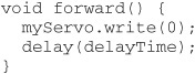
All user-defined functions must indicate the kind of data they return (for use elsewhere in the sketch). If the function doesn’t return any data, you use void instead. You must also include parentheses to enclose any parameters that may be provided for use in the function. In the case of the forward user-defined function, there are no parameters, but remember that you need the ( and ) characters just the same.
That defines the function; you need only call it from elsewhere in your sketch to use it. Just type its name, followed by a semicolon to mark the end of the statement line:
forward();
See arduino_servo.pde for a full demonstration of an Arduino sketch that runs a servo forward and backward, then briefly stops it, using the detach method. The effect of the sketch is most easily seen when using a servo modified for continuous rotation.
arduino-servo.pde
On the Web: Operating Two Servos
The Arduino can control two servos with the same ease as one. All it takes is that you create a second instance (copy) of the Servo object, giving it a unique name. For example, in a two-wheeled differentially steered robot you might call one servo object servoLeft and the other servoRight.
As a bonus project, check out the RBB Online Support site (see Appendix A) for full details, hookup diagrams, and example code for using the Arduino with two motors.
On the support site you’ll also find extended code and additional project ideas for a project I call the ArdBot, a low-cost and expandable platform for experimenting with Arduino robotics. The basic ArdBot, with Arduino and protyotyping board, is shown in Figure 37-8.
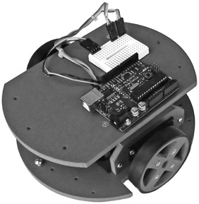
Figure 37-8 The “ArdBot,” with Arduino microcontroller and mini solderless breadboard for experimenting. Learn more about this robot on the RBB Online Support site.
Flow Control Structures
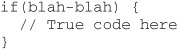
Flow control structures tell the sketch what conditions must be met to perform a given task. By far the most common flow control structure is the if command. It tests if a condition exists or doesn’t exist, then branches off execution of the program accordingly. The if structure looks like this:
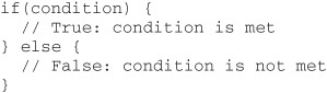
Condition is an expression, usually something that determines if A equals B, as in:
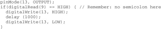
if(digitalRead(9) == HIGH)
This tests if digital pin D9 is HIGH. If it is, then the program performs the True code, because the condition is met. Otherwise, it performs the False code. A complete example goes like this, where the value of digital pin D9 makes the LED on pin D13 briefly flash:
Note that in this case there is no code for when the condition is False. This is acceptable, and quite common. Because there is no code for when the condition is False, the else command is omitted, as are its corresponding brace characters.
Be mindful of the curly braces! You need a set of curly braces to enclose the code for any True condition.
And if you want separate code for when the condition is False, you must add the else command and its set of braces:
![]()
Conditions for the if test typically test that something is equal to something else, but there are other possible comparisons. Here are the most common:

Take special note of double equals signs for equal to. Using = will not give you what you want. You need to use ==.
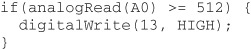
A practical example is testing if the voltage on an analog pin is above or below the halfway point—the halfway point being 511 (possible values are 0 to 1023). The following short example tests if the value at analog pin A0 is above the halfway point, or 512 and over. If it is, the LED on digital pin D13 is turned on.
Using the Serial Monitor Window
The Arduino provides a quick and easy way to get feedback about any running program when it’s tethered to its host PC via the USB cable. Built into the Arduino is the ability to talk to the PC via serial communications. You merely set up the serial link with
Serial.begin(9600);
and then send values or text to the PC with
Serial.println(value);
The result is shown in the Serial Monitor window, which you display by choosing Tools->Serial Monitor.
For example, suppose you want to see the digital value of a voltage applied to analog input pin A0. Set up the communications link in the setup( ) function, then repeatedly read the analog pin and return its value into the Serial Monitor window.
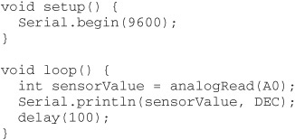
Note the optional data format in the Serial.println statement. The DEC tells the Arduino to return the value as a DECimal number. Also notice the delay statement. It’s usually a good idea to include a slight delay to slow down processing when communicating back with your PC. The Arduino can process these commands faster than the serial link can accommodate, and there’s a risk of losing data if the data is shuttled too quickly.
Some Common Robotic Functions
Arduino supports a number of built-in programming statements specifically useful for robotics. I’ll briefly review just a few of them here, but you’ll want to review these and others more fully in the Arduino language reference, available on the www.arduino.cc Web site. Examples of most of these statements can be found in Part 8 of this book.
![]() tone. Outputs a frequency on an I/O pin that, when connected to a piezo buzzer element, generates a tone. The tone to play is specified by its frequency, with a value of 440 being concert pitch A.
tone. Outputs a frequency on an I/O pin that, when connected to a piezo buzzer element, generates a tone. The tone to play is specified by its frequency, with a value of 440 being concert pitch A.
![]() shiftOut. Converts a byte (or more) of data to a stream of bits, which can then be sent one at a time to some external device, typically a shift register IC. The shift register receives the serial data and reconstructs it as parallel data outputs. The shiftOut statement is useful for minimizing the number of I/O pins used with external devices.
shiftOut. Converts a byte (or more) of data to a stream of bits, which can then be sent one at a time to some external device, typically a shift register IC. The shift register receives the serial data and reconstructs it as parallel data outputs. The shiftOut statement is useful for minimizing the number of I/O pins used with external devices.
![]() pulseIn. Measures the width of a single pulse, from 10 μs to 3 minutes. You can specify which I/O pin to use, whether you’re looking for a LOW-to-HIGH or HIGH-to-LOW transition.
pulseIn. Measures the width of a single pulse, from 10 μs to 3 minutes. You can specify which I/O pin to use, whether you’re looking for a LOW-to-HIGH or HIGH-to-LOW transition.
![]() analogWrite. Outputs a series of pulses whose duration, or duty cycle, is controlled via software—so-called pulse width modulation, or PWM. It’s very commonly used to control the speed of a DC motor. The analogWrite statement may be used only with specifically marked digital pins. On the core board designs (Duemilanove, Uno, etc.), these pins are 3, 5, 6, 9, 10, and 11.
analogWrite. Outputs a series of pulses whose duration, or duty cycle, is controlled via software—so-called pulse width modulation, or PWM. It’s very commonly used to control the speed of a DC motor. The analogWrite statement may be used only with specifically marked digital pins. On the core board designs (Duemilanove, Uno, etc.), these pins are 3, 5, 6, 9, 10, and 11.
FYI
See Chapter 22, “Using DC Motors,” for more information on PWM, especially as it relates to controlling the speed of motors.
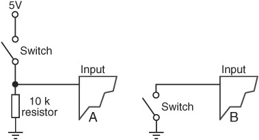
Figure 37-9 Standard connections for reading the value of a simple switch. In A, the switch is used with a 10 kΩ pull-down resistor. This keeps the value of the pin LOW until the switch is closed. In B, the switch relies on the Arduino’s built-in pull-up resistor to keep the pin HIGH until the switch is closed.
Using Switches and Other Digital Inputs
Reading the value of a switch or other digital input is a straightforward affair with the Arduino. Simply use the digitalRead statement and indicate the digital pin you wish to use:
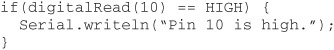
Figure 37-9A shows the traditional method of connecting a switch to a digital input pin. The 10 kΩ pull-down resistor ensures that the pin stays LOW as long as the switch is open. When the switch closes, the pin goes HIGH.
While resistors are the most common approach for wiring a switch to an Arduino, they are not strictly required, as the Arduino has its own pull-up resistors that can be turned on and off. When the pull-up resistors are engaged, the pins stay at a HIGH level, unless taken LOW by a switch or other input. To set the pull-up resistor, specify that the pin is an INPUT, then set its value to HIGH with digitalWrite.
![]()
In this case, you can do away with the resistor, as shown in Figure 37-9B. Note that the built-in resistors are pull-ups, which means the switch goes LOW when activated. Your program code needs to be changed accordingly:
if(digitalRead(10) == LOW)
Interfacing to DC Motors
You’ve already seen how to use the Arduino with servo motors. You can also use the microcontroller with DC motors. The I/O pins on the Arduino can provide only about 40 milliamps of current, not enough to directly power the typical DC motor. But as described in Chapter 40, “Interfacing Hardware with Your Microcontroller or Computer,” you can use a motor H-bridge or other driver to run most any size of DC motor with your Arduino.
![]() To turn the motor on, apply HIGH to the Enable/PWM line.
To turn the motor on, apply HIGH to the Enable/PWM line.
![]() To control the direction of the motor, apply HIGH or LOW to the Direction line of the H-bridge.
To control the direction of the motor, apply HIGH or LOW to the Direction line of the H-bridge.
![]() To control the speed of the motor, use the analogWrite statement to send a PWM signal to the Enable/PWM line. (Remember: To do this, you must connect the line to one of the digital I/O pins on the Arduino that supports PWM.)
To control the speed of the motor, use the analogWrite statement to send a PWM signal to the Enable/PWM line. (Remember: To do this, you must connect the line to one of the digital I/O pins on the Arduino that supports PWM.)
In the following sketch, a motor bridge module is connected to digital pins D11 (for Enable/PWM) and D12 (for Direction). After setting up the two pins as outputs, the sketch repeats the steps of turning the motor on fully, reversing its direction, then slowing it down to 50 percent.
arduino_motor_control.pde
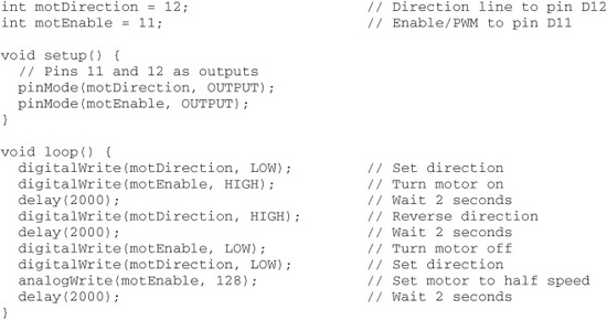
The PWM pulsed output is disabled when you use digitalWrite on the same pin. In the example, digitalWrite is used to enable the motor at full speed, but you can also use analogWrite and set the PWM duty cycle to 255. However, digitalWrite is a more efficient use of the microcontroller when controlling the speed of the motor is not needed.
If your motor doesn’t turn when its PWM duty cycle is set to 128 (50 percent), try a higher value. Not all motors will run at duty cycles below 50 percent.

Figure 37-10 Expansion shield for testing and working with various kinds of motors. This model supports R/C servos, stepper motors, and DC motors. (Photo courtesy Adafruit Industries.)
Besides fashioning your own H-bridge circuit or board, you can use any of a number of third-party expansion shields that contain their own H-bridge modules. An example is shown in Figure 37-10, which offers connection points for working with two servos, two stepper motors, and up to four DC motors. The shield is designed so that you can provide separate power to the motors than what’s supplied to the Arduino.