
Chapter 48
Danger, Will Robinson!
Everyone complains that a robot is good for nothin’—except, perhaps, providing its master with a way to tinker with gadgets in the name of “science”! But here’s one useful application you can give your robot in short order: fire and smoke detection. As this chapter will show, you can easily attach sensors to your robot to detect flames, heat, smoke, and poisonous gases, making your robot a kind of mobile safety inspector.
![]()
Now, don’t go treating your robot sentry as foolproof. The methods described here are for experimental use only. For reasons we’ll get into, a robot may not be the best at detecting smoke or gas in a room; for true safety, leave these tasks to approved fire, gas, and smoke detector appliances designed for the job.
![]()
Source code for all software examples may be found at the RBB Online Support site. See Appendix A, “RBB Online Support,” for more details. To save page space, the lengthier programs are not printed here. The support site also offers source code with added comments, parts lists (with sources) for projects, updates, extended construction plans, and more examples you can try!
Flame Detection
Flame detection requires little more than a sensor that detects infrared light and a circuit to trigger a motor, siren, computer, or other device when the sensor is activated. As it turns out, almost all phototransistors are specifically designed to be sensitive primarily to infrared or near-infrared light. You need only connect a few components to the phototransistor and you’ve made a complete flame detection circuit.
Interestingly, the detector can “see” flames that we can’t. Many gases, including hydrogen and propane, burn with little visible flame. The detector can spot them before you can, or before the flames light something on fire and smoke fills the room.
DETECTING THE ULTRAVIOLET LIGHT FROM A FIRE
Of all the methods of detecting fire and flame, using ultraviolet light sensors is probably the most popular. UV flame sensors are made for the central heating system industry and used in gas and oil furnaces to detect proper pilot light and flame settings. You can use these same sensors in your robot to look for open flame. Be warned, however, that these sensors are not cheap, and you must always use a UV sensor with an appropriate amplifier.
The Hamamatsu R2868 Flame Detector UVTron sensor, and associated amplifier board, are among the most used flame detectors for amateur robotics. It’s among the least expensive, and available through Acroname and other robotics specialty online retailers. There are others, such as the Honeywell C7027, that perform the same task.
WATCHING FOR THE FLICKER OF FIRE
Fire flickers. You can use this flame modulation in a robot fire detection system to help differentiate what is a real fire and what is likely just sunlight streaming through a window or light from a nearby incandescent lamp. By detecting the rate of flicker from a fire and referencing it against known values, it is possible to reduce some of the false alarms.
The technique is beyond the scope of this book, but with a bit of ingenuity, you could create a simple flame-flicker system using just a phototransistor (don’t use a photoresistor), and microcontroller with an analog-to-digital input. The phototransistor will pick up the infrared and near-infrared light emitted by the fire.
Your program reads the value of the photoresistor 15 to 20 times a second, looking for the telltale pattern of flame over sunlight or incandescent lighting. The closer the patterns match, the greater the likelihood that there is a real fire. For example:
![]() If the intensity of the light doesn’t change, it’s either the sun or light from a steady source like a flashlight. Either way, it’s not a flame. (Well, the sun is one huge ball of flame, but it’s 83 million miles away, and as long as it stays at that distance, we’ll be okay.)
If the intensity of the light doesn’t change, it’s either the sun or light from a steady source like a flashlight. Either way, it’s not a flame. (Well, the sun is one huge ball of flame, but it’s 83 million miles away, and as long as it stays at that distance, we’ll be okay.)
![]() If the light flickers at regular intervals, at the same intensity, it’s probably an AC-operated incandescent lamp or fluorescent light fixture, and, again, we’re not interested.
If the light flickers at regular intervals, at the same intensity, it’s probably an AC-operated incandescent lamp or fluorescent light fixture, and, again, we’re not interested.
![]() If the intensity of the light constantly changes and flickers at random, there is a greater chance the light is from a flame.
If the intensity of the light constantly changes and flickers at random, there is a greater chance the light is from a flame.
DETECTING INFRARED FROM A FIRE OR FLAME
Fire emits infrared heat, some of which is in the near infrared (just beyond dark red) part of the electromagnetic spectrum, and some in the far infrared spectrum. A simple circuit for sensing near infrared from a fire is shown in Figure 48-1. It uses a phototransistor, which is naturally responsive to infrared light in the near infrared region—about 800 nanometers (nm) to about 1500 nm. For best results, place an IR-pass filter in front of the phototransistor to block extraneous light. An IR-pass filter is one that lets in infrared light, but blocks all others.
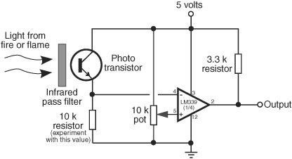
Figure 48-1 Basic test circuit for detecting the light emission of a nearby fire or flame. Adjust the 10 kΩ potentiometer for best sensitivity.

Figure 48-2 This thermopile sensor contains eight infrared detectors in an 8×1 array. It provides a serial output with the instantaneous value of each of the detectors. (Photo courtesy Devantech.)

Some phototransistors have their own built-in IR-pass filters. These are typically set to accept IR light at about 950 nanometers. If the phototransistor has a brown, dark blue, or dark red tint to it, then you know it already has an IR-pass filter built in.
You should be aware that this type of sensing circuit leaves much to be desired, as it will trigger on all kinds of light, including from the sun, an incandescent lamp, and your robot’s own infrared navigation sensors. But it’s a useful technique for general testing and experimentation when your robot lives in a controlled environment.
A better, but much more expensive, technique is to use a thermopile sensor, like the one shown in Figure 48-2. This particular unit contains eight infrared imaging sensors, aligned in a horizontal array. It’s said to be able to detect a candle flame at 6 feet. Because it has more than just one sensor in it, it can provide a kind of simple mosaic of the heat pattern of whatever it’s pointed at.
Fire that consumes any organic material burns hydrogen, which emits carbon dioxide, CO2. This emission puts out a very distinct “spike” of infrared radiation at about 4300 nanometers (see Figure 48-3). By using a very specific IR-pass filter that blocks all radiation except that at 4300 nanometers, the sensor is effectively blind to background radiation, including natural and artificial sources.
Unfortunately, IR-pass filters for 4300 nanometers are not common and are frightfully expensive when purchased new. But you just might luck out and find one at some dank and dusty surplus joint near your hometown or in the storeroom at school.
Smoke Detection
“Where there’s smoke, there’s fire.” For less than $15, you can add smoke detection to your robot’s long list of capabilities and, with a little bit of programming, have it wander through the house checking each room for trouble.
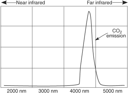
Figure 48-3 Carbon dioxide (CO2) is emitted during a fire; this emission is accompanied by a “spike” in the 4300-nanometer infrared region of the electromagnetic spectrum.
You can build your own smoke detector using individually purchased components, but some items, such as the smoke detector cell, are hard to find. It’s easier to use a commercially available smoke detector and modify it for use with your robot. In fact, the process is so simple that you can add one to each of your robots. Tear the smoke detector apart and strip it down to the base circuit board.
Many smoke detectors employ an ionization chamber that uses a mildly radioactive substance, Americium 241. This human-made element has a half-life of over 400 years (it keeps going and going and …), but the ionization chamber can become ineffective after less than 10 years, due to dust and other contaminants. Using a very old surplus or used alarm will render your “Smokey the Robot” fairly useless at detecting the smoke of fires.
HACKING A SMOKE ALARM
You can either buy a new smoke detector module for your robot or scavenge one from a commercial smoke alarm unit. The latter tends to be considerably cheaper—you can buy quality smoke alarms for as little as $7 to $10. In this section, I’ll discuss hacking a commercial smoke alarm, specifically a First Alert model SA300, so it can be directly connected to a robot’s computer port or microcontroller. Of course, smoke alarms are not all designed the same, but on many, the basic construction is similar to that described here. You should have relatively little trouble hacking most any smoke detector you happen to use.
However, you should limit your hacking attempts to those smoke alarms that use traditional 9-volt batteries. Certain smoke alarm models, particularly older ones, require you to use AC power or specialized batteries. These are not suitable for use on your battery-powered bot.
Checking for Proper Operation
Start by checking the alarm for proper operation. If it doesn’t have one already, insert a fresh battery into the battery compartment. Put plugs in your ears (or cover up the audio transducer hole on the alarm). Press the “Test” button on the alarm; if it is properly functioning, the alarm should emit a loud, piercing tone.
If everything checks out okay, remove the battery and disassemble the alarm. Less expensive models will not have screws but will likely use a “snap-on” construction. Use a small flat-headed screwdriver to unsnap the snaps.
Getting Inside the Smoke Alarm
Inside the smoke detector is a circuit board that consists of the drive electronics and the smoke detector chamber.
Either mounted on the board or located elsewhere will be the piezo disc used to make the loud tone. Remove the circuit board, being careful you don’t damage it. Examine the board for obvious “hack points,” and note the wiring to the piezo disc. More than likely, there will be either two or three wires going to the disc:
![]() Two wires to the piezo disc: The wires will provide ground and +V power. This design is typical when you are using all-in-one piezo disc buzzers, in which the disc itself contains the electronics to produce the signal for audible tones, or the disc is used as a simple speaker.
Two wires to the piezo disc: The wires will provide ground and +V power. This design is typical when you are using all-in-one piezo disc buzzers, in which the disc itself contains the electronics to produce the signal for audible tones, or the disc is used as a simple speaker.
![]() Three wires to the piezo disc: The wires will provide ground, +V power, and a signal that causes the disc to oscillate with an audible tone.
Three wires to the piezo disc: The wires will provide ground, +V power, and a signal that causes the disc to oscillate with an audible tone.
Find the wire that serves as ground. On the SA300 it’s easy because the battery terminals are labelled + and − right on the board. Find the ground (negative or –) terminal, and connect the COM black lead from the multimeter to it. Connect the red test lead to one of the wires or connections to the piezo disc.
Replace the battery in the battery compartment, and depress the “Test” button on the alarm. Watch for a change in voltage. For a two-wire disc, you should see the voltage change as the tone is produced. For a three-wire disc, try each wire to determine which produces the higher voltage; that is the one you should use. If you are using an oscilloscope, find the wire that produces the cleanest on/off pulse.
Once you have determined the functions of the wires to the piezo disc, remove the disc and save it for some other project. Retest the alarm’s circuit board to make sure you can still read the voltage changes with your multimeter. Then clip off the wires to the battery compartment, noting their polarity.
On the First Alert SA300, the piezo disc has three leads; the one that produced the largest voltage change was in the upper right corner. So I soldered a long “tap-off” wire to it from the underside of the printed circuit board. On an oscillosope, this voltage change showed as a series of very fast sawtooth pulses; these pulses are what actually produce the high-pitched tone on the piezo disc. Figure 48-4 shows the SA300 unit, before it was disassembled and gutted, with the piezo disc removed, and tap-off wire soldered to the PCB.
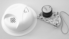
Figure 48-4 The guts of a typical battery-operated smoke detector.
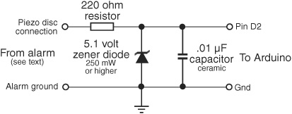
Figure 48-5 A 5.1-volt zener diode clamps the output of the smoke alarm to about 5 volts, helping to protect the input of the microcontroller. You may also wish to add extra protection in the form of an opto-isolator or buffer (see Chapter 41).
INTERFACING THE ALARM TO A MICROCONTROLLER
See Figure 48-5 for interfacing the output of a battery-operated smoke detector to a microcontroller or other circuit that expects 5-volt input. To be on the safe side, the circuit uses a 5.1-volt zener diode and current-limiting resistor to prevent a possible overvoltage condition. Most battery-operated smoke alarms operate at up to 9 volts (a few up to 12 volts), and you don’t want more than 5 volts going to your microcontroller.
![]()
Remember: There’s always a chance of damaging your microcontroller when connecting it to alien devices. Exercise care and proceed at your own risk!
The circuit in Figure 48-5 assumes an output voltage to the piezo sounder of the smoke detector of 7 to 12 volts. You may wish to add an opto-isolator (see Chapter 40), which adds protection between the detector and the robot’s electronics.
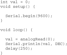
By way of example, let’s assume that the microcontroller periodically polls the input pin that is connected to the smoke alarm circuit board. The program, shown in smoke_detector.pde (for the Arduino), checks the pin several times each second. When the pin goes HIGH, the smoke alarm has been triggered and the Arduino’s LED lights up.

smoke_detector.pde

TESTING THE ALARM
Once the smoke alarm circuit board is connected to the microcontroller or computer port, test it and your software by triggering the “Test” button on the smoke alarm.
RUNNING ON 5 VOLTS
I found that the First Alert SA300 unit operated at 5 volts, rather than the 9 volts from its regular battery. Or I should say that when operating at 5 volts it triggered and sounded its alarm when pressing the Test button. I have no idea if the unit’s smoke detection abilities are diminished at the reduced voltage, but I suspect this may be the case. Anyway, running the board at 5 volts saves you from having to power it from a separate battery, so it’s worth looking into.
On the other hand, at the reduced voltage there wasn’t enough rise in signal to trigger the Arduino; the voltage at pin D2 wasn’t enough to register as a HIGH. An option in this case is to connect a voltage comparator to the hacked output of the smoke detector and adjust its reference voltage to trigger at the reduced signal level (in my tests it was about 2 volts). See Chapter 40 for additional information on using voltage comparator circuits.
LIMITATIONS OF ROBOTS DETECTING SMOKE
You should be aware of certain limitations inherent in robot fire detectors. In the early stages of a fire, smoke tends to cling to the ceilings. That’s why manufacturers recommend that you place smoke detectors on the ceiling rather than on the wall. Only when the fire gets going and smoke builds up does it start to fill up the rest of the room.
Your robot is probably a rather short creature, and it might not detect smoke that confines itself only to the ceiling. This is not to say that the smoke detector mounted on even a 1-foot-high robot won’t detect the smoke from a small fire; just don’t count on it. Always use a regular smoke alarm for actual protection, and treat the robot’s smoke alarm as an educational toy.
Detecting Dangerous Gas
Smoke alarms detect the smoke from fires but not noxious fumes. Some fires emit very little smoke but plenty of toxic fumes, and these are left undetected by the traditional smoke alarm. Moreover, potentially deadly fumes can be produced in the absence of a fire. For example, a malfunctioning gas heater can generate poisonous carbon monoxide gas.
Just as there are alarms for detecting smoke, so there are alarms for detecting noxious gases, including carbon monoxide. Such gas alarms tend to be a little more expensive than smoke alarms, but they can be hacked in much the same way as a smoke alarm.
Combination units that include both a smoke and a gas alarm are also available. You should determine if the all-in-one design will be useful for you. In some combination smoke-gas alarm units, there is no simple way to determine which (smoke or gas) has been detected.
BUILDING A NOXIOUS GAS DETECTOR CIRCUIT
There may not be many smoke detector modules available for robotics experimentation, but the same is not true of gas detectors. Parallax, Seeedstudio, and many others offer a wide variety of single-board gas detection modules that you can readily incorporate into your robot designs. No hacking required.
Figure 48-6 shows an example propane LPG sensor and module that is easily connected to a microcontroller. The sensor is a Hanwei MQ-6 gas detector, capable of picking up many kinds of volatile gases, with a special sensitivity to LPG, propane, and butane. A typical hookup diagram is shown in Figure 48-7. A sample program for the Arduino is provided in propane.pde. Connect the output of the sensor to analog pin A0.

Figure 48-6 Gas sensor detects propane, LPG, and other toxic and flammable gases. (Photo courtesy Parallax Inc.)
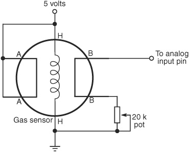
Figure 48-7 Basic connection diagram for a gas sensor that uses an internal heating element. Adjust the potentiometer for best sensitivity and range.
Note that the circuit and demo programs work with many of the gas and air quality sensors made by the same company (but not all; some need a much more sophisticated connection and heat/cool cycle). For example, the MQ-3 alcohol sensor could be used to create a Breathalyzer-bot. Check the datasheet that comes with the sensor you’re using for details.
Adjust the 20 kΩ pot for best sensitivity. Since you probably don’t have a calibrated gas source to work from, you’ll have to simply guess at the best setting. Start with the pot at its midpoint, and try adjusting it in small steps higher or lower.
![]()
Follow the manufacturer’s recommended procedure for testing and using this, or any, noxious gas sensor, or serious injury or death could result. Test only outdoors or in well-ventilated areas, and away from flame, sparks, or heat sources. Use for experimental purposes only!
propane.pde
WARM-UP, ADJUSTMENT, AND USE
The MQ-6 works by warming the air inside a chamber. It does this with a built-in heater element (this is why the sensor gets a little warm during operation). You should always allow the sensor to come to temperature before trying to take a reading. The datasheet for the sensor says to preheat the thing for 24 or more hours, but for general testing and use as a robotic gas sniffer, preheating for a minute or so will do the trick.
Run the program, open the Serial Monitor window, and let the sensor preheat. After preheating, dial the 20 kΩ pot so the reading is right in the middle. On my prototype, turning the pot to the extremes resulted in readings from 0 to 330. So I dialed in 160 as the approximate midpoint.
For the gas test I used an ordinary butane lighter, snuffing out the flame so only the gas escaped. (Of course, I did this in a well-ventilated room, and only for a few seconds.) The reading quickly climbed above 850, indicating a heavy concentration of the gas. It takes several minutes for the reading to return to normal. Don’t touch the sensor during operation, as this will affect the accuracy of the reading.
The heater runs full-time and consumes about 750 milliwatts of power at 5 volts. That equates to 150 milliamps. Don’t rely on a little 9-volt battery to operate your Arduino and gas sensor. You’ll need a beefier battery pack, perhaps a set of six or eight D cells. Remember that when the Arduino is powered from the USB port you are limited to 500 milliamps. Don’t use the gas sensor with other current-hogging components, such as servo motors.
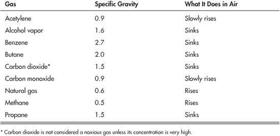
HEAVY GAS, LIGHT GAS
As with smoke detection, where the gas detector is located has great bearing on whether it detects anything. The reason: Gases either rise or fall in air, depending on their specific gravity. If a gas is lighter than air, it rises—same thing as when you let go of a helium-filled balloon.
![]() Gases that are lighter than air, such as methane and natural gas, will rise to the ceiling and may not even be noticed (depending on the concentration) by a gas detector mounted on a robot that’s only 6″ tall.
Gases that are lighter than air, such as methane and natural gas, will rise to the ceiling and may not even be noticed (depending on the concentration) by a gas detector mounted on a robot that’s only 6″ tall.
![]() Gases that are heavier than air, or about the same specific gravity as air, will sink to the ground. Sensors for these gases, which include benzene and propane, are ideal candidates for robot experimenting.
Gases that are heavier than air, or about the same specific gravity as air, will sink to the ground. Sensors for these gases, which include benzene and propane, are ideal candidates for robot experimenting.
Heat Sensing
In a fire, smoke and flames are most often encountered before heat, which isn’t felt until the fire is going strong. But what about before the fire gets started in the first place, such as when a kerosene heater is inadvertently left on or an iron has been tipped over and is melting the nylon clothes underneath?
Realistically, heat sensors provide the least protection against a fire. But heat sensors are easy to build, and, besides, when the robot isn’t sniffing out fires it can be wandering through the house giving it an energy check or reporting on the outside temperature or … you get the idea.
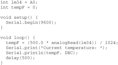
Figure 48-8 shows a basic but workable circuit centered around the popular LM34 temperature sensor. This device is relatively easy to find and costs just a few dollars. The output of the device, when wired as shown, is a linear voltage. The voltage increases 10 millivolts (mV) for every rise in temperature of 1°F. The temperature.pde sketch provides an example for the Arduino microcontroller for reading the sensor.
The LM34 provides output relative to degrees Fahrenheit. Use the LM35 if you want to measure in centigrade.
temperature.pde
A variation on the LM34 theme is shown in Figure 48-9. Here, the sensor is connected to an LM339 voltage comparator, for sensing any temperature above some limit you set via the 10 kΩ potentiometer. For example, you might “calibrate” the circuit to trigger at about 100°F. The output of the LM339 comparator will trigger when the temperature exceeds that.
The easiest way to calibrate the circuit is to set the potentiometer when the temperature is what you want. If that’s not possible, you can infer the setting by using your multimeter to measure the output voltage of the LM34 at some known temperature. Calculate the difference between the known temperature and the desired temperature, multiply this result by 0.01 (remember, the LM34 changes 1 mV per degree F). Add or subtract the difference from the known temperature.

Figure 48-8 Circuit diagram for an LM34 Fahrenheit temperature sensor. For best results, mount the sensor on a small piece of aluminum or other metal, using a thermally conductive adhesive.
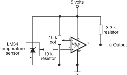
Figure 48-9 Use an LM339 comparator to set a trigger when a certain temperature is reached. The 10 kΩ potentiometer adjusts the temperature at which to trigger the comparator.
For instance, if the current temperature is 75°F, and you want to trigger at 100°F, the difference is +25°F. If the voltage from the LM34 is 2.4 volts at 75°F, add 0.25 (25 × 0.01). Set the potentiometer so that the reference voltage to the comparator is 2.65 volts (2.4 + 0.25).
Robotic Firefighting Contests
If the firefighting robot bug bites you hard, consider entering your machine in the annual Trinity College Fire Fighting Home Robot Contest (see www.trincoll.edu/events/robot/ for additional information, including rules and a description of the event).
This contest involves timing a robot as it goes from room to room in a house-like test field (the “house” and all its rooms are at a reduced scale). The object is to find the fire from a candle and snuff it out in the least amount of time. Separate competitions involving a junior division (high school and younger) and a senior division (everyone else) help to provide an even playing field for the contestants.
Several local robotics groups host their own firefighting contests. Do a Web search for a group near you, and see what kind of competitions they offer.
Finally, Go Out and Do!
Few other moments in life compare to the instant when you solder that last piece of wire, file down that last piece of metal, tighten that last bolt, and switch on your robot. Something you created comes to life, obeying your commands and following your preprogrammed instructions. This is the robot hobbyist’s finest hour. It proves that the countless evenings and weekends in the workshop were worth it after all.
I started this book with a promise of adventure—to provide you with a treasure map of plans, diagrams, schematics, and projects for making your own robots. I hope you’ve followed along and built a few of the mechanisms and circuits that I described. As you finish reading, you can make me a promise: improve on these ideas. Make them better. Use them in creative ways that no one has ever thought possible. Create that ultimate robot that everyone has dreamed about.
Your ideas, suggestions, and other comments are welcome. If you see a mistake in a circuit or mechanism, I’ll make sure the next edition of this book is corrected. Visit the support site for this book; see Appendix A. If you have a unique robot design, why not share it with others? Send me details of your robots—finished or in process.
Now, stop reading—and do. Impress us all!