Appendix D
Electronic Reference
Formulas
Here are some of the more common electronic formulas you will encounter in your electronics work. Many of these formulas have been with us for a long time.
OHM’S LAW
Ohm’s law calculates the relationship between power, voltage, current, and resistance. The basic formulas are:
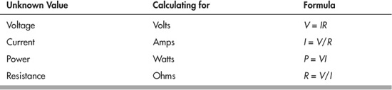
where:
V = voltage (in volts)
I = current (in amps)
P = power (in watts)
R = resistance (in ohms)
Example:
To find the power in a circuit consuming 100 volts at 10 amps, multiply volts times amps (100 × 10 = 1000). Answer: 1000 watts.
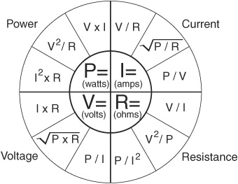
The Ohm’s law wheel can be used to help you remember the formula for calculating one value when you know the other two. Start with any of the four unknown values in the center of the circle, then apply the appropriate formula, given the two values that you do know. For instance, to calculate volts when you know power and current, you’d use:
V = P/I
CALCULATING RESISTANCE
The resistance of a single resistor in a circuit is easy to surmise. But resistance changes when you add resistors in parallel or in series.
Calculate Two Resistors in Parallel

![]()
R1 and R2 are the values of the two resistors; Rtotal is the total resistance.
Calculate Three or More Resistors in Parallel
![]()
R1, R2 (and so forth) are the values of the resistors. Rtotal is the total resistance.
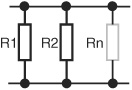
Calculate Resistors in Series
![]()
Rtotal = R1 + R2 + Rn
R1, R2 (and so forth) are the values of the resistors. Rtotal is the total resistance.
CALCULATING CAPACITANCE
These formulas can be used to calculate total capacitance in a circuit. Note that the formulas are basically the inverse of those for resistors.
Calculate Capacitors in Parallel
Ctotal = C1 + C2 + Cn
C1, C2 (and so forth) are the values of the capacitors. Ctotal is the total capacitance.
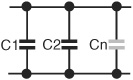
Calculate Two or More Capacitors in Series
![]()
![]()
C1, C2 (and so forth) are the values of the capacitors. Ctotal is the total capacitance.
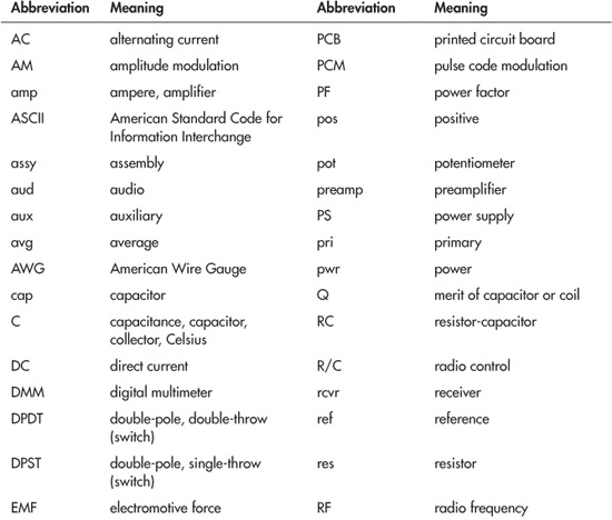
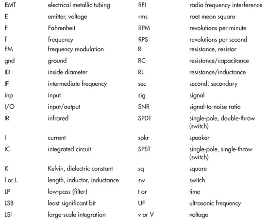
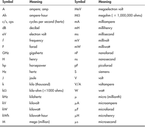
Abbreviations
Abbreviations may be used for descriptions and circuit diagrams used with electronics. Many of the most common abbreviations are listed here. Note that the use of abbreviations may not follow any kind of standard, and the accepted use of some abbreviations may come and go over time.
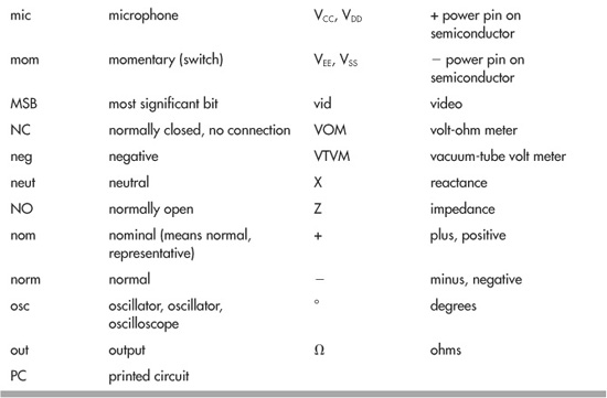
Letter Symbols Used in Electronics
These symbols are commonly used in descriptions of electronic circuits.
Numbering Units in Electronics
The science of electronics uses what’s known as SI, or International System of Units, to denote very large and very small numbers. The most common unit names used in electronics are as follows:
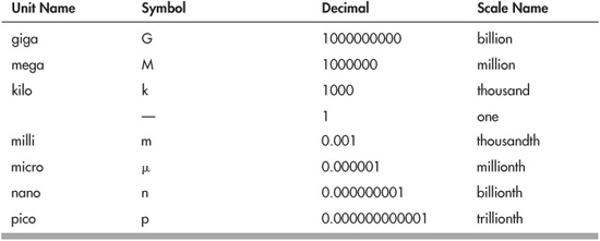
You may convert between numbering units by moving the decimal point. SI units smaller than 1 each differ by three decimal spaces between them. Move the decimal point three spaces right or left to accomplish the conversion.
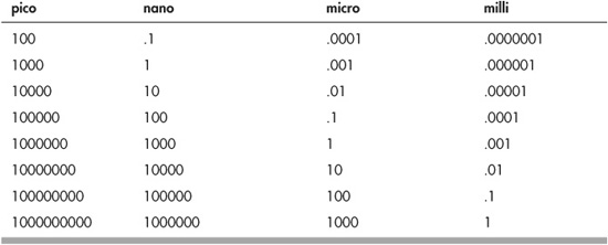
Examples:
Capacitance: 10,000 μF = 10 nF = 0.01 μF
Time: 1000 μs = 1 ms
The Six Most Common Units of Measure in Electronics
Electronics is a science based on math and relationships of numbers. Different electronic components have different units of measure, and these units are used in making calculations. A large percentage of the study of electronics boils down to the following six most common units of measure.
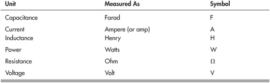
![]() A farad is a very large unit. Capacitance is typically measured in millionths of a farad (microfarad or μF) or billionths of a farad (picofarad or pF). See the section “Numbering Units in Electronics” on converting from one numbering unit to another.
A farad is a very large unit. Capacitance is typically measured in millionths of a farad (microfarad or μF) or billionths of a farad (picofarad or pF). See the section “Numbering Units in Electronics” on converting from one numbering unit to another.
![]() Similarly, a henry is a large unit, and inductors are routinely measured in millionths of a henry (milcrohenry or μH).
Similarly, a henry is a large unit, and inductors are routinely measured in millionths of a henry (milcrohenry or μH).
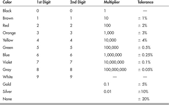
Resistor Color Coding
Because of their small size, resistors are usually coded for identification. The most common coding scheme for resistors is a series of colored bands.
RESISTOR COLOR CODE CHART
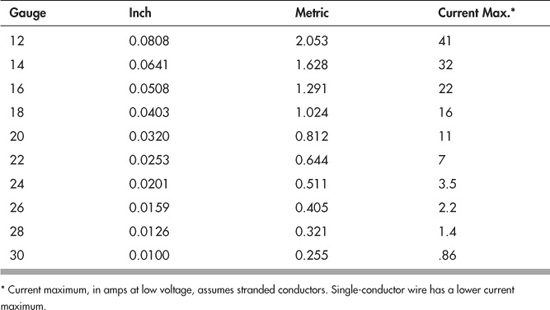
Wire Gauge
Gauge defines the diameter of wire. The larger the wire, the smaller the gauge. Only the diameter of the electrical conductor(s) is considered; the size of insulation or other nonconductive material on the outside of the wire is ignored. This chart shows the cross-section diameter of wire from 12 to 30 gauge, listed in both inch and metric sizes. Wire gauge is sometimes referred to as AWG wire size; AWG stands for American Wire Gauge.
Diameter