
3D Characterization of Particle Interaction Using Synchrotron Microtomography
ABSTRACT. Granular particles experience sliding and rolling as they are sheared. X-ray Synchrotron Microtomographic (SMT) was used to acquire 3D scans of a triaxial specimen of sand at eight axial strain levels. The specimen measures 9.5 mm in diameter and 20 mm in height. Several particles within and outside the shear band were identified and tracked as shearing progressed. The analysis reveals that sliding of particles within the shear band is much more significant than particles outside the shear band. Particles within the shear band continue to rotate throughout the experiment while particles outside the shear band exhibit insignificant rotation.
KEYWORDS: sand, triaxial, computed tomography
1. Introduction
The mechanical behavior of granular materials is highly dependent on the arrangement of particles, particle groups and associated pore space. These geometric properties comprise the so-called structure or fabric of a material. The literature lacks three-dimensional (3D) experimental measurements of fabric changes of sheared granular materials at the particle level. As a result, many researchers used the Discrete Element Method (DEM) to quantify particles sliding and rotation (e.g. Oda et al. 1997). Experimental measurements of particles interaction provide key answers to calibrate models for better understanding on the behavior of such materials. In the literature, internal structure analysis techniques are mainly classified as destructive (e.g. specimen stabilization and thin-sectioning) and nondestructive techniques (e.g. magnetic resonance imaging (MRI), ultrasonic testing, x-ray radiography, and computed tomography (CT)). Recently, x-ray CT was utilized to conduct qualitative analysis of sheared soils such as shear band visualization (e.g., Alshibli et al., 2000), however still only few studies extended the analysis to include quantitative measurements of physical properties and tracking the movements of particles. This might be due to the lack of image resolution to visualize particles for some x-ray CT systems. Furthermore, such quantitative analysis requires challenging particle identification techniques and computational power. For example, Chang et al. (2003) developed algorithms to track the movement of glass beads at different loading stages from 3D CT images. They embedded a steel ball in the mix of glass beads, which served as a reference point to track relative locations of the other beads. Similarly, Alshibli and Alramahi (2006) tracked the interaction of spherical plastic beads in a cylindrical triaxial specimen at different axial strain increments. The particles have holes which helped to track their relative movement, rotation, and interaction with each other. The data were then used to calculate particles rotation and local strains at the particle-to-particle microscopic level during shear.
Synchrotron x-ray microtomography (SMT) has emerged as the most powerful non-destructive scanning technique that can produce a high-resolution 3D of scanned objects (e.g. Matsushima et al., 2006; Hasan et al., 2008). This paper presents a quantification of 3D particles sliding and rotation within a sheared sand specimen. The analysis focuses on comparing the behavior of particles within and outside the shear band during shear.
2. Materials and methods
A miniature triaxial apparatus was especially fabricated to conduct the in situ axisymmetric triaxial experiment. It should be light weight and small in size to facilitate mounting it on the stage of the SMT scanner and must rotate freely to acquire the SMT scans. The small size also helps in increasing the resolution of the SMT scans. The triaxial cell was mounted on the SMT scanner stage using a clamping chuck via a pin attached to the base of the cell. The miniature triaxial apparatus system has similar capabilities as the conventional triaxial cell except that the specimen is confined using vacuum. It consists of a stepper motor to drive the loading ram at a constant displacement rate, a load cell located inside the test cell, a cylindrical acrylic chamber, two endplates, top and base plates, a latex membrane, and a tubing line to connect the specimen to the vacuum. The motor was powered by 12 volts electricity and automatically controlled by a computer. A data acquisition card acquired the signal from load cell with an interface to a computer.
The specimen is cylindrical in shape and measures 9.5 mm in diameter and 20 mm in height. Dry F-75 Ottawa sand was used to prepare the specimen. It is natural uniform silica sand that was mined from Ottawa, Illinois, USA and marketed by the American Silica Company. It has a mean particle size (d50) of 0.16 mm, specific gravity of solid particles of 2.65, minimum and maximum void ratio values of 0.486 and 0.805, respectively. The specimen has a relative density of 90% (dry bulk density of 1.75 g/cm3). Vacuum was used to apply a confining pressure (σ3) of 58 kPa. The specimen was compressed axially (σ1) at a displacement rate of 0.1 mm/min. Compression was paused at 0%, 2.5%, 5%, 7.5%, 10%, 12.5%, 15%, and 17.5% nominal axial strain (ε1) to acquire the SMT scans. It took approximately 2 hours to acquire each scan.
The CT scans were acquired using Sector 13-BMD synchrotron microtomography beamline at the Advanced Photon Source (APS), of the Argonne National Laboratory (ANL), Illinois, USA. An x-ray beam with energy of 33 keV was used to scan the specimen which produced a good contrast between sand particles and the void space. The voxel size of images was 10.26 µm at which individual sand particles were clearly seen by a naked eye. Algorithms were developed using the Interactive Data Language (IDL) software to reconstruct the image projections, to build 3D renderings, and to further process the scan images (Thompson et al. 2006).
3. Particle sliding and rotation during shear
A group of particles within and outside shear band regions were visually identified, tracked, and analyzed. They were randomly selected at the initial stage (before compression/shearing). Then, the same particles were tracked in the subsequent shearing stages. The displacement fields (Δx, Δy, and Δz), and horizontal and vertical rotation angles (Δκ and Δλ) were calculated as follows:
[1] ![]()

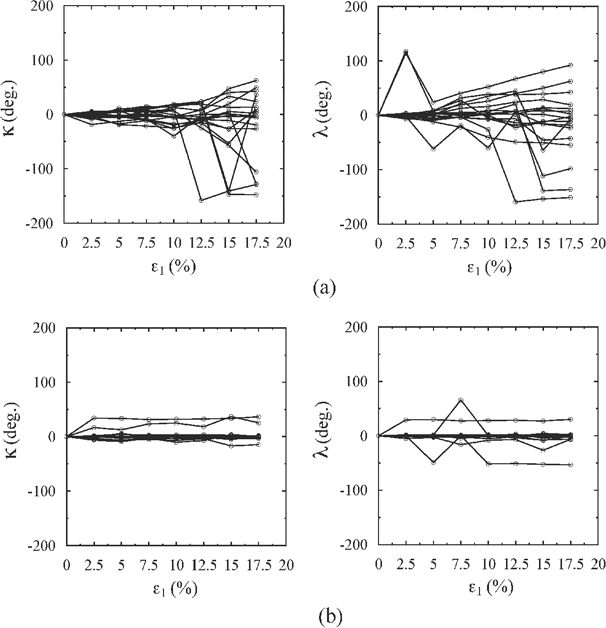
where subscript n denotes the coordinate at the nth strain stage and subscript o denotes the coordinate at the initial stage (i.e. when ε1 = 0%). The rotation of each particle was calculated as the change in the orientation of the particle major axis. Angles λ and κ define the orientation with respect to the z-axis (axial direction) and x-y plane (axisymmetric direction), respectively. Two rotation angles can fully describe the rotation of particles since the x-y plane represents the axisymmetric plane in triaxial testing.
Figure 1 shows the visualization of the evolution of the tracked particles displacements and rotations within and outside shear band. They are displayed in y-z plane (axial plane) with each figure frame serves as a reference for particles location. Note that there are some particles that might exist between these particles, but they were not displayed in the figure. There are two primary mechanisms of particle interaction visualized here: interparticle sliding and rolling. Particles within the shear band exhibit a significant sliding as the test continued due to the intensive shearing within the shear band where particles slide together globally as well as slide relative to each other. Globally, all particles within the shear band move downward to the right parallel to the shear band inclination angle. To some extent, some particles lose their interlocking which permits them to slide/shear (either face-to-face or face-to-edge) with their neighboring particles. On the other hand, particles outside the shear band exhibit insignificant sliding or rolling. Some particles within the shear band show a considerable rotation while sliding. They exhibit rotation in a continuous or an oscillatory mode either in the horizontal (axisymmetric) or vertical (axial) directions.
Figure 2 displays the displacement in the x, y and z directions of the tracked particles within and outside shear band at each stage. The curves show that particles within the shear band continue to slide throughout the test. Little change in curvature is shown for the x- and y-displacements at 5% axial strain. No change in curvature is shown at 5% axial strain for the z-displacement curve. The x-, y- and z-displacements increase as axial strain increases and the rate decreases after 12.5% axial strain. At ε1 = 17.5%, some particles slide as high as 1.1 mm (11.6% of specimen initial diameter (Do) or 6.9d50) for the x-displacement, 0.35 mm (3.7% of Do or 2.2d50) for the y-displacement, and 1.1 mm (5.5% of specimen initial height (Ho) or 6.9d50) for the z-displacement. On the other hand, particles outside shear band show much less sliding when compared to those within the shear band. At ε1 = 17.5%, particles slide only 0.07 mm (0.07% of Do or 0.4d50) for the x-displacement, 0.05 mm (0.05% of Do or 0.3d50) for the y-displacement, and 0.1 mm (0.05% of Ho or 0.9d50) for the z-displacement.
Figure 1. Illustrative example of particles evolution during shear
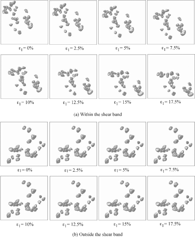
Figure 2. Displacements of tracked particles (a) within the shear band; (b) outside the shear band
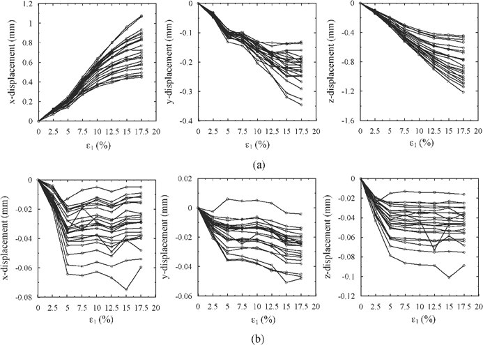
However, the trends show that these particles experience a small amount of sliding until 5% axial strain. Then, they become almost flat and stabilize after 5% axial strain, which implies particles no longer slide. Note that the 5% axial strain is the axial strain close to the peak stress state. The curves demonstrate that before the peak stress state, particles in both locations experience sliding due to the axial loading. After the peak stress state, deformations localize into the shear band when particles outside the shear band experience little change as shearing continue along the shear band.
4. Conclusions
The SMT was successfully utilized to visualize the evolution of particles sliding and rolling and to calculate their orientation distributions in the axisymmetric and axial directions. Particles within and outside the shear band region slide during shearing until peak stress state is reached. Then, only particle within the shear band continue to slide during the post peak stress regime. Sliding of particles within the shear band is much more significant than particles outside the shear band. Particles within the shear band continue to rotate throughout experiment while particles outside the shear band exhibit insignificant rotation.
Figure 3. Changes in horizontal (axisymmetric) rotations (Δκ) and vertical (axial) rotations (Δλ) of tracked particles (a) within the shear band; (b) outside the shear band
5. Acknowledgments
The authors gratefully acknowledge the financial support of the National Science Foundation grant number CMMI- 0653957. The data presented in this paper were collected using the x-ray Operations and Research Beamline Station 13-BMD at Argonne Photon Source (APS), Argonne National Laboratory. We thank Mark Rivers of (APS) for help in performing the scans. Use of the Advanced Photon Source was supported by the U. S. Department of Energy, Office of Science, Office of Basic Energy Sciences under Contract No. DE-AC02-06CH11357.
6. References
Alshibli, K. A., and Alramahi, B. A., “Microscopic Evaluation of Strain Distribution In Granular Materials during Shear”, ASCE J. Geotech. Geoenviron. Eng., vol. 132, no. 1, pp. 483-494, 2006.
Alshibli, K. A., Sture, S., Costes, N. C., Frank, M., Lankton, M., Batiste, S., and Swanson, R., “Assessment of Localized Deformations in Sand Using x-ray Computed Tomography”, ASTM Geotech. Testing J., vol. 23, no. 3, pp. 274-299, 2000.
Chang, C.S., Matsushima, T., and Lee, X., “Heterogeneous strain and bonded granular structure change in triaxial specimen studied by computer tomography”, ASCE J. Eng. Mech., vol. 129, no. 11, pp. 1295-1307, 2003.
Hasan, A., Alshibli, K., Heinrich, J., Rivers, M., and Eng, P., “Visualization of Shear Band in Sand Using Synchrotron Micro-Tomography”, Proc. GeoCongress 2008, Characterization, Monitoring, and Modeling of GeoSystems (GSP 179), ASCE, New Orleans, pp. 1028-1035, 2008.
Matsushima, T., Uesugi, K., Nakano, T., and Tsuchiyama, A., “Visualization of grain motion inside a triaxial specimen by micro X-ray CT at SPring-8”, Advances in X-ray Tomography for Geomaterials, J. Desrues, G. Viggiani, and P. Besuelle (eds.), ISTE Ltd., London, pp. 255-261, 2006.
Oda, M., Iwashita, K., and Kakiuchi, T., “Importance of particle rotation in the mechanics of granular materials”, Powder & Grains 97, Balkema, Rotterdam, 1997.
Thompson, K.E., Willson, C.S., and Zhang, W., “Quantitative computer reconstruction of particulate materials from microtomography images”, Powder Technology, vol. 163, pp. 169-182, 2006.