
Integration of 3D Imaging and Discrete Element Modeling for Concrete Fracture Problems
ABSTRACT. This paper describes a collaboration where synchrotron-based x-ray CT images of micromechanical experiments on cement-based composites are used to develop discrete element computational models of the material. Preliminary results are presented showing how 3D images are used to create computational models, as well as the resulting simulations from those models. The results show a good qualitative agreement between simulations and experiments, opening a door that will allow us to establish previously difficult-to-characterize properties such as cement-aggregate interfaces.
KEYWORDS: synchrotron x-ray CT, 3D image analysis, lattice model, fracture
1. Introduction
Predictive simulation of fracture in heterogeneous materials has traditionally been an ill-posed problem due to the complex microstructural features that do not lend themselves to simple geometric representations. Planer cracks, penny-shaped cracks, and spherical inclusions can provide useful insight into damage and fracture behavior, however, they can fall short as honest descriptors of real heterogeneous microstructure. The work described here is aimed at developing new ways to measure the physical microstructure of damage and fracture, and use those measurements to create realistic numerical models. Our approach is to identify key microstructural features in 3D tomographic images, and create lattice-type finite element models that match the measured microstructure (Landis and Bolander 2009). Below we provide an overview of the 3D imaging, the micromechanical experiments, and preliminary simulations results.
2. Instrumentation and experiments
The 3D imaging described herein was conduced at beamline 5BM of the Advanced Photon Source (APS). The high flux and monochromatic synchrotron x-ray source allows us to image subtle differences in x-ray absorption, and therefore subtle changes in microstructure. In all the tests here, an x-ray energy of 30 kV was used, tuned such that the specimen absorbed roughly 90% of the beam. Image acquisition and optics were set up such that acquired images had a spatial resolution of 6 microns per pixel.
The focus of our experiments was in situ fracture of small (4 mm diameter by 4 mm long) Portland cement-based specimens loaded in a split cylinder configuration. The materials were a conventional Portland cement paste (hardened cement and water), while the second was a mortar that had the same relative amount of cement and water as the cement paste but included fine aggregate particles not exceeding 80 microns. Specimens had a water-to-cement ratio of 0.42, corresponding to a conventional concrete with a moderate to high strength. For the specimens with aggregates, the aggregate volume fraction was 30%.
In situ imaging of fracture processes was made possible through the use of a load frame built to allow tomographic scans while the specimen is under load. An in-line transducer measures applied force, while a pair of capacitance transducers measures platen-to-platen displacement. Load was applied by both a screw actuator (coarse displacements) and a piezoelectric stack actuator (fine displacements). A schematic diagram of the load frame is shown in Figure 1.
Figure 1. Photograph of load frame in place at x-ray beam line
We selected a split cylinder configuration, which produced predominately tensile stresses in an easily controlled compression loading. The experimental protocol was set up as follows. First a tomographic scan was made of an unloaded, undamaged specimen. Then we applied a load close to, but not exceeding, the failure load, and held that load while a second tomographic scan was made. Finally, the load was increased until the specimen ruptured, when a third tomographic scan was made. Tomographic scans consisted of 1500 views over a rotation of 180 degrees. Tomographic reconstructions were made using a filtered back projection algorithm for a parallel beam. The resulting 3D images were 1299 by 1299 by 800 voxels at 6 microns per voxels.
Figure 2. Vertical slice images illustrating split cylinder fracture. Cylinder is 4 mm diameter. Note that due to non-uniform deformation, not all features in the damaged specimen image (right) appear in the same plane as the undamaged image (left)
An example of pre- and post-fracture scans is shown in Figure 2, where a specimen with aggregate particles has been loaded to rupture. One of the significant aspects of this kind of test is that we are able to measure internal changes in structure that result from damage and fracture in a single specimen. One example of this is a measure of specific fracture energy, where we make the calculation based on the non-recoverable external work as measured in the load-deformation plot, and divide this amount by the new surface area created by fracture, as measured in the tomographic images (Landis et al., 1999). Of particular note is the fact that, to the degree allowed by the spatial resolution of the scans, in this measurement we are able to account for the numerous crack branches and fragmentation that occurs as a result of heterogeneous fracture.
3. Lattice formulation and simulation
Lattice representations of heterogenous materials have been used for a number of years, emerging from work in statistical physics (Herrmann and Roux, 1990). The philosophy of the approach used here is that statistical variations and disorder can be explicitly represented in a way that resembles the actual material.
In the approach applied here, lattice topology is based on the Delaunay tessellation of nodal points within the specimen domain. The dual Voronoi tessellation defines the elastic and fracture properties of the lattice elements (Berton and Bolander, 2006). This discretization involves a three-phase representation of the material meso-structure as follows: hardened cement paste, aggregates, and cement-aggregate interface.
Figure 3. Simulation of split cylinder test: a) dark regions show fracture development from central region of model toward the load platens; and b) frontal view of fracture surface
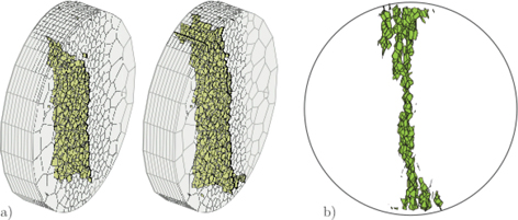
Figure 3 shows the simulated fracture pattern for a split-cylinder without aggregate inclusions. Fracture initiates in the central region of the specimen, where the tensile stress is quasi-uniform, and propagates toward the load platens. Qualitatively, the general pattern of fracture is consistent with that observed in the in situ tomographic scans (Figure 4). Specifically, while the mesh was relatively coarse, we obtained qualitative agreement in both the physical features of the fractured specimen (appropriate crack branching and crack spatial distribution) and the shape of the load deformation curve.
Figure 4. Vertical tomographic section of fractured cement paste specimen. Image highlights multiple cracks that appear at the load points after the main vertical tensile crack forms
4. Examination of specimens with spherical inclusions
Of particular interest in random heterogeneous materials such as concrete are the properties of the cement-aggregate interface. Presented here are the first steps of a process that will enable us to characterize interfaces in situ. A model specimen was developed in which the aggregate particles were spherical beads. This simplification was done to facilitate meshing of the lattice model, and it allows us to remove geometric variations in aggregates from the list of experimental variables. The selected aggregates were nominal 0.5 mm spheres made of soda lime glass. In order to vary the cement-aggregate interface bond strength, both smooth (as purchased) and etched beads were used. The specimens were etched using a very dilute HF acid. An example of a tomographic scan of such a specimen is shown in Figure 5, where the spherical aggregates appear as a relatively uniform graylevel in the image.
Figure 5. Vertical tomographic section of fractured specimen with glass bead aggregates
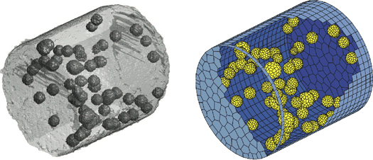
As the primary objective of this work was to match numerical to real specimens, we developed an image processing routine that allowed us to isolate the individual glass bead aggregates and determine the coordinates of the centroid so that a 3D discrete element model can be created from the images of actual specimens. Segmentation of the glass bead aggregates was accomplished through a simple 3D standard deviation analysis. Since the beads have a relatively uniform density, they can be distinguished from the more widely varying cement matrix. Once the aggregates are identified in the 3D images, we can apply routines that establish the centroid of each aggregate in the specimen. A table of aggregate locations can be then be used to create a lattice model of the specimen that has matching aggregate locations. Figure 6 shows a 3D rendering of the segmented tomographic image data along with the corresponding lattice model.
Figure 6. Illustration of segmented tomographic image with isolated aggregates and corresponding lattice model discretization
5. Summary
We have presented some preliminary work on the development of numerical models of random heterogenous composites that are meshed based on a direct correspondence between features of the numerical specimen and the real specimen. The work is presented as a first step in micromechanical characterizations of complex cement matrices and interfaces.
6. Acknowledgements
The authors gratefully acknowledge the support of a collaborative grant from the U.S. National Science Foundation (0625030 and 0625593).
7. References
Berton, S., and Bolander, J. E., “Crack band modeling of fracture in irregular lattices”, Computational Methods in Applied Mechanics and Engineering, vol. 195, p. 7172-7181, 2006.
Herrmann, H. J., and Roux, S., Statistical Models for the Fracture of Disordered Media, North-Holland, Amsterdam, 1990.
Landis, E. N., Nagy, E. N., Keane, D. T., and Nagy, G., “A Technique to Measure Three-Dimensional Work-of-Fracture of Concrete in Compression”, Journal of Engineering Mechanics, vol. 125 no. 6, 1999, p. 599-605.
Landis, E. N., and Bolander, J. E., “Explicit representation of physical processes in concrete fracture”, Journal of Physics D: Applied Physics, (in press).