
Development of a Bending Test Apparatus for Quasi-dynamical Evaluation of a Clayey Soil Using X-ray CT Image Analysis
Visualization using industrial x-ray CT scanner
ABSTRACT. Local deformation of clay cover on the landfill for radioactive waste could cause serious damage to the environment. In order to evaluate the performance of clay barrier of the clay cover to local deformation, it is useful to conduct a bending test of the clay material. This bending test would facilitate understanding about the performance of clay barriers used to cover radioactive wastes. In this paper, a new testing method for obtaining the engineering properties of the cover soils was developed and the effectiveness of this method was evaluated. It was found that the local deformation of cover soil would cause catastrophic failure and that areas of low density would not as long as the clayey soil was compacted sufficiently.
KEYWORDS: compacted clay liner, landfill, industrial x-ray CT scanner, bending test
1. Introduction
A compacted clay liner (CCL) is an impermeable barrier material that is placed at the bottom and top (cover) of landfill. As for use of the CCL to the cover system, there are potential issues such as aging of the CCL that result in local deformation of the CCL that occur as the settlement load becomes unbalanced. If this potential issue occurred in the actual site, serious environmental problems would result. Landfill for very low level radioactive waste was constructed in France Aube (Gourc and Camp, 2005 and Gourc and Oliver, 2006). The research group of Lirigm, Joseph Fourier University, Grenoble, in France has maintained a field monitoring problem and discovered that the localized settling of landfill surface. In order to observe the behavior of the CCL due to local settlement of the waste, an in-situ burst test was performed. The objective of the burst test was to simulate the critical force required to damage the CCL, namely to create cracks in this liner. This test helped display to visual observation the cracks on the surface of CCL. Meanwhile, the industrial x-ray computed tomography (CT) scanner installed at the X-Earth Center of Kumamoto University was used to visualize the crack propagation of the CCL at the each step during the loading level during the punching and bending tests. Authors developed a new bending test apparatus which can be operated in x-ray CT room. This test apparatus has made it possible to evaluate the crack generation in the specimen of CCL during incremental loading and without stress release between acquisitions of new images (Mukunoki et al., 2008).
The objective of this paper is to confirm the test performance of the new bending test apparatus for x-ray CT scanner and to evaluate the bending property and the durability of the CCL used in the actual site.
2. Experimental method
2.1. Materials
Figure 1 shows a grain size distribution curve of CCL specimen tested. The compacted clayey specimen had a soil density of 2.72 t/m3, optimum moisture content of 16%, its liquid limit and plastic index are 43.6% and 24.3%, respectively. In this study, the disk specimen with a diameter of 150 mm and the thickness of 25 mm was prepared for and subjected to a symmetric bending test with displacement control.
2.2. New bending test apparatus
The new test apparatus was used in this study. Figures 2(a) and (b) illustrate a schematic of the newly developed bending test apparatus that was used with the specimen with circular shape (referred as a disk specimen hereafter) and display a photograph of the installed test apparatus. The improved feature for this testing apparatus is that a new type of tester was developed. This testing apparatus has the loading system with an electrical actuator installed at the top of the test system as shown in Figures 2(a) and (b). The actuator can be operated by a remote controller. Additionally, the bottom plate was prepared especially for this CT system and an entire test apparatus can be fixed on the specimen table. Hence, all processes for testing the CCL can be conducted in the x-ray CT room. In this study, 300 kV was chosen. The total number of voxels in each x-ray image slice is 2048×2048 and the beam thickness is 1 mm (i.e. the dimension of a voxel is 0.195× 0.195×1 mm3).
The features of this test apparatus can be drawn as follows:
1) to perform the symmetrical-loading test in the x-ray CT room; and,
2) to scan the specimen at each deformation level with x-ray CT scanner without stress release.
Figure.1 Grain size distribution curve
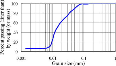
Figure.2 (a) The schematic of the developed bending test apparatus
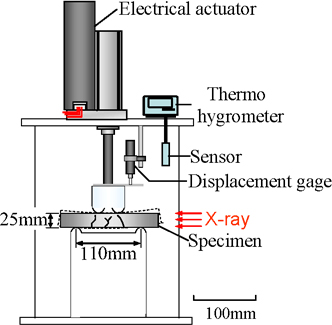
Figure.2 (b) A photograph of the developed bending test apparatus installed in the X-ray CT shield room
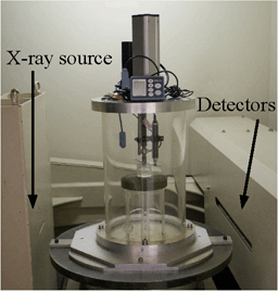
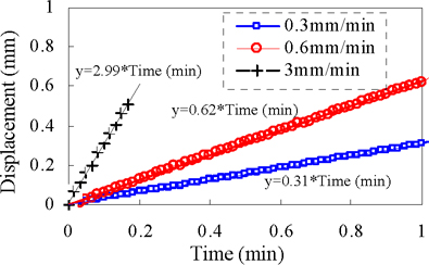
Figure.3 Calibration of loading speed versus time
3. Results and discussion
3.1. Check the performance of the bending test apparatus
Figure 3 shows displacement versus time due to loading with a speed of 0.3, 0.6 and 3.0 mm/min. The electrical actuator installed gave the linear relationship between displacement and time and it was confirmed that the loading speed was precisely maintained in this system. In this study, the loading speed was 0.6 mm/min.
3.2. Load-displacement relationship
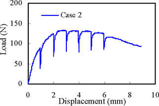
Figure 4 shows the load-displacement curve at the center of the specimen with previous test apparatus (Case 1). In this case, the CCL specimen was loaded in the soil test room and the specimen had to be moved to the CT room. Hence, the sample rebound as shown in Figure 4. Eventually, at least 65% of the displacement was rebounded at the center of the specimen. This phenomenon probably resulted in close hair cracks, artefacts in the CCL specimen due to rebounding. Figure 5 shows the load-displacement curve at the center of the specimen with new test apparatus (Case 2) shown in Figures 2(a) and (b). In this newly developed case, the actuator that was used can control the displacement very precisely, there is no observation of displacement rebounded as shown in Figure 4.
The actuator motion must be stopped during the CT scanning. The scanning time is 2.5 minutes. Times the number of CT images, it took at least 62.5 minutes to scan one CCL. As the material is clayey soil, it is difficult to avoid the stress release. However, it is impossible to make the scanning time shorter than 62.5 minutes, so the issue of stress release is not discussed in this paper. These stress releases are evident in Figure 2 and displayed as a reduction in the load at increments of 62.5 minutes.
Figure.4 Load-displacement relationship obtained from previous bending test apparatus (Case 1)
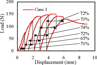
Figure.5 Load-displacement relationship obtained from the developed bending test apparatus (Case 2)
3.3. X-ray CT image
Figures 6 and 7 (a), (b) show the x-ray CT images of vertical-cross section at the different steps from the initial condition for Case 1 and 2, respectively. At the initial condition of the CCL specimen: at the displacement level of 0 mm as shown in Figures 6(a) and 7(a), some cracks can be seen in the CT images of the CCL. Cracks were generated from the displacement of 3mm around the bottom surface and they grew with increase in the displacement level. Also, the point of the crack increased along the direction of propagation as keeping with the peak point of load-displacement curve for Case 1 and Case 2. Cracks generated in the CCL specimen seem not to have a relationship to the heterogeneity in the initial condition. The width equal of the crack in Case 2 was smaller than Case 1. It is conceivable that the crack was closed during rebound.
3.4. Visualization of 3D image of low density area extracted
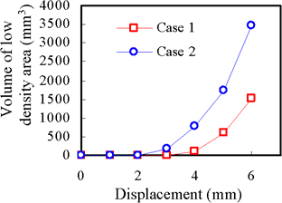
Figure 8(a), (b) show the images that was extracted from the low density area for Case 1 and Case 2. Both images were seen from the view point of the bottom surface of CCL specimen. The crack which developed from the center of the specimen can be observed to have almost the radial spread at each step in the loading process. In the 3mm displacement the crack has occurred in both Cases, however in Case 1 the number and sized of the crack was smaller than in Case 2. It is difficult to judge a difference of both Cases in displacement of 4 mm, 5 mm and 6 mm. Therefore, Figure 9 shows the length of the crack to the direction of specimen thickness. Figure 10 shows the volume of low density area. These values could be obtained from Figure 8(a), (b) using the previous apparatus (Case 1) and in the newly developed one (Case 2). The length of the crack obtained from Figure 8(b) was slightly greater than that from Figure 8(a) as shown in Figure 9. Then, the volume of low density area shown in Figure 10 was reconstructed under the condition of less than 0 of CT-value. The volume of the low density area in the case of using the newly developed apparatus was approximately two times greater than the previously developed one. Likewise, the previous apparatus would underestimate the volume of low density area because of not avoiding the rebounding of specimen; namely, this result pointed out that the rebound effect was reduced.
Figure.6 X-ray CT images due to bending loading at each displacement level for Case 1
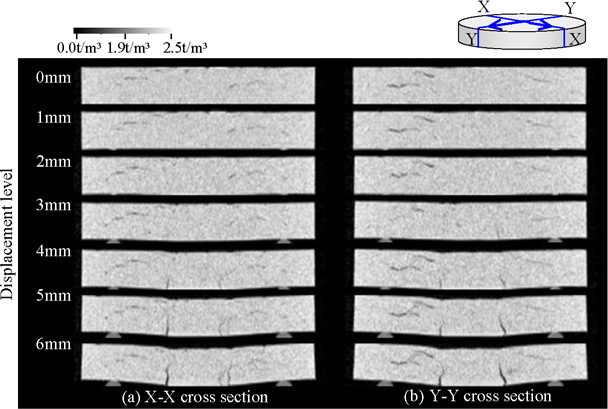
Figure.7 X-ray CT images due to bending loading at each displacement level for Case 2
Figure.8 3D image of the low density area for Case 1 and Case 2
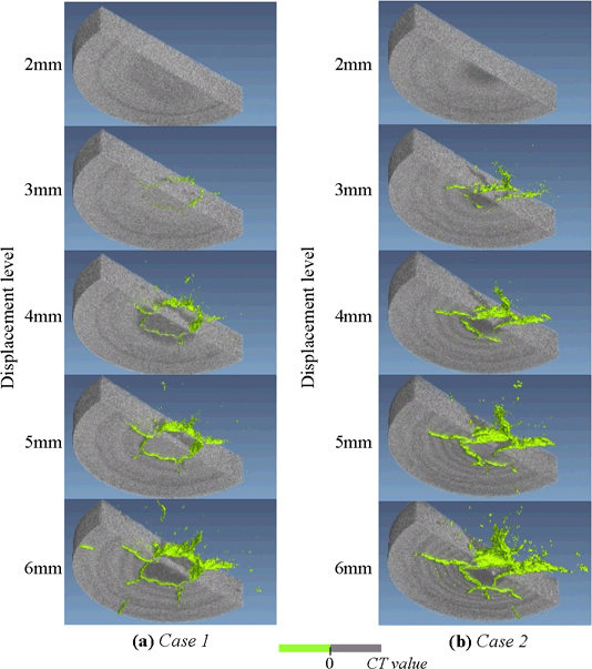
Figure.9 Distance of crack due to bending load for Case 1 and 2.
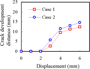
Figure.10 Volume of low-density area due to bending load for Case 1 and 2.
As in these results, to be able to perform the mechanical test in the X-ray CT room is a significant improvement and enables us to observe the phenomena while minimizing rebound artefacts in the CCL material that are caused by the unloading process.
4. Conclusions
The bending test apparatus for X-ray CT was newly developed to observe the deformation behavior of the compacted clay specimen due to symmetric loading in this paper. The conclusion can be summarized in the following:
(1) the developed bending test apparatus performed well in the x-ray CT shield room;
(2) use of the newly developed bending test apparatus made it possible to visualize the deformation process and the crack generation in the compacted clay specimen, because the sample could be symmetrically loaded with in the x-ray CT scanner;
(3) the obtained x-ray CT images of the compacted clay specimen that is subjected to various loads and load rates can be effectively evaluated with minimal rebound artefacts; and,
(4) as long as the clayey soil was compacted sufficiently, the local deformation would cause catastrophic failure of the clay cover and not areas of low density.
5. References
Gourc, J., and Camp, S. Proposal of joint program about the behavior of clay used as landfill cap cover and likely to crack under extension, Lirigm, University of Grenoble, France, 2005.
Gourc, J.P. and Olivier, F. “Overview of landfill instrumentation techniques for the monitoring of waste settlements”, pp199-206, Proceedings of the Sixth Japanese-Korean-French Seminar On Geo-Environmental Engineering, 2006.
Mukunoki, T., Otani, J., Maekawa, A., Camp, S. “Investigation of Crack Behavior on Cover soils at Landfill using X-ray CT”, pp213-219, Advances in X-ray Tomography for Geomaterials-GeoX2006, 2006.
Mukunoki, T., Nakano, T., Otani, J., A., Camp, S., Gourc, J.P. “Evaluation of Cracks in Cover Soils due to local deformation using X-ray CT”, pp243-248, Proceedings of the sixth Japanese-Korean-French Seminar On Geo-Environmental Engineering, 2008.
Kenter, J.A.M., “Application of Computerized Topography in Sedimentology”, vol. 8, pp. 201–211, Marine Geotechnology, 1989.