
X-ray Imaging of Fluid Flow in Capillary Imbibition Experiments
Influence of compaction and localized deformation
ABSTRACT. We used an industrial scanner to image capillary imbibition processes in order to get some insight into fluid motion processes in several porous rocks. Images obtained at different stages in standard capillary rise experiments on intact and damaged rock samples are analyzed. The geometry of the water front depends on the rock microstructure and its curvature changes as the water rises up to the top of the samples. The mechanical damage was induced either during creep experiments at increasing stress levels or in standard triaxial tests. The continuous recording and localization of acoustic emissions was extremely useful in identifying clusters where damage was concentrated. We show that the velocity and the geometry of the water front are strongly disturbed by localized or distributed damage.
KEYWORDS: x-ray imaging, capillary imbibition, reservoir rocks, image analysis
1. Introduction
Imaging techniques have been widely used to investigate microstructural features in porous rocks. Among them x-ray CT scanning methods are of common use in geosciences (Van Geet et al., 2000). In order to study hydromechanical coupling in reservoir rocks, we developed a three stage methodology combining x-ray CT scanning on intact rock samples, mechanical tests with acoustic emissions recording to investigate the localization of induced damage (Fortin et al., 2006), and again x-ray CT scanning on the damaged samples after unloading. Some of our results have been published recently (David et al., 2008); we present here a complementary data set on a larger number of porous rocks, focusing on the influence of rock microstructure, compaction processes and compaction bands on fluid flow patterns.
2. Description of the selected rocks and methodology
Four rocks were selected for the present study: two sandstones – Bentheim sandstone (Romberg quarry, Nothwestern Germany) and Vosges sandstone (Eastern France), as well as two calcareous rocks – Majella grainstone (central Apennines, Italy) and Saint-Maximin limestone (Paris basin, France). Both calcareous rocks have been extensively studied by Baud et al. (2009). Table 1 gives the rock composition and some relevant attributes like porosity, mean grain diameter, permeability and peak diameter on mercury porosimetry spectrum.
Table 1. Microstructural attributes of the studied rocks
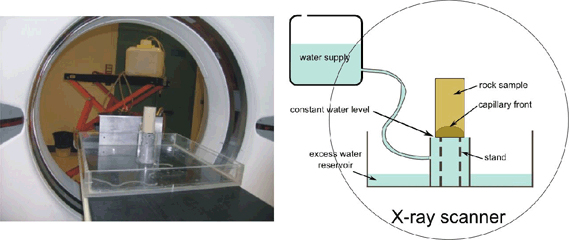
The methodology has been described in detail by David et al. (2008). In few words, dry cylindrical rock samples (diameter 40 mm, length 80 mm) are put on a stand under an industrial scanner available at Institut Français du Pétrole, France. Our experimental device allows for water to be brought into contact with the bottom part of the sample: at this point capillary rise starts and one image of the central cross-section is taken every 2.5 seconds by the x-ray CT scanner, until the water reaches the top of the core sample. Figure 1 shows a picture and a sketch of the experimental device.
Figure 1. Experimental device used for our experiments
In Figure 2, we show an example of a snapshot taken during capillary rise in each rock sample. The “processed” images show how image processing techniques described by David et al. (2008) make the analysis of water invasion easier thanks to an enhancement of density contrast between dry (dark) and wet (bright) zones.
Figure 2. Example of raw images obtained and image processing applied
An automated procedure allows us to obtain from each series of enhanced images the height of the water front in the center and at the border, from which the velocity of capillary rise and the mean radius of curvature of the water front are calculated (David et al., 2008). Complementary experiments were performed without imaging, to measure the mass of water entering the rock samples during capillary rise.
3. Comparison of capillary parameters and microstructural interpretation
As can be seen in Figure 2, the density maps reveal heterogeneous features in every rock sample: white (i.e. dense) spots or lines in Bentheim and Majella respectively, black spots (i.e. more porous zones) in Vosges and Saint-Maximin. Significant differences appear also in the geometry of the water front. A quantitative analysis of our capillary experiments is shown in Figure 3.
Figure 3. Evolution of mass intake, height of water front and radius of curvature
The geometry of the water front changes during capillary rise, and is rounder in Bentheim and Saint-Maximin compared to Majella and Vosges. The mass and height are usually plotted vs. the square root of time. Two parameters can be inferred from these plots: firstly the “A” parameter (cm.s−1/2) which is the slope of the height plot (assumed to be linear) and secondly the “B” parameter (g.cm−2.s−1/2) which is the slope of the mass plot normalized to the surface in contact with water (also assumed to be linear, at least until water reaches the top). Considering imbibition into a single pipe, the “A” parameter which describes the kinetics of water imbibition should be a constant depending on the pipe diameter. A third parameter is calculated, the Hirschwald coefficient, which is the water saturation when the water front reaches the top of the sample, derived from the mass at the plateau in Figure 3 (Zinszner et al., 2007). The results are summarized in Table 2.
Table 2. Capillary parameters of the studied rocks
To go further, we intend to interpret these data in terms of rock microstructure. Figure 4 shows how the capillary parameters scale with microstructural parameters.
Figure 4. Correlation between capillary and microstructural parameters
Except for one point, there is a clear correlation between capillary parameter “A” and the peak diameter on the mercury porosimetry spectrum. This shows that the relevant length scale for capillary processes is given by the mercury injection test (the so-called pore entry diameter), in agreement with our previous results (David et al., 2008). Notice however that according to Washburn’s equation in the single pipe model (Zinszner et al., 2007), one would expect a linear relationship between capillary parameter “A” and the square root of pore diameter, rather than diameter. The data point clearly off the trend is the one corresponding to the Vosges sandstone. This discrepancy might be explained by the large clay content in this rock, as it is well known that clay coating or filling significantly modifies capillary processes in porous rocks. The middle plot shows a clear correlation between the ratio of capillary parameters “B/A” and the rock porosity. This ratio is related to the mass intake per unit volume during capillary imbibition, and is clearly controlled by the bulk porosity. Finally on the last plot we found for all rocks that the smaller the kinetics of water imbibition (low A parameter), the flatter the water-air interface (large radius of curvature at mid height), or equivalently the faster the capillary rise, the smaller (i.e. the rounder) the capillary front.
4. Influence of mechanical compaction on capillary processes
In our previous study, we have conducted mechanical tests in a triaxial setup on Bentheim sandstone samples in the brittle regime. It was clearly shown that mechanical damage strongly modifies fluid flow patterns when comparing CT scan images during capillary imbibition tests on intact and deformed rock samples (David et al., 2008). Here we present our results for Saint-Maximin limestone, a much weaker rock than Bentheim sandstone. In Figure 5 we present the mechanical data (i.e. axial/volumetric strain vs. differential stress) for the creep tests conducted at increasing stress levels at constant confining (3 MPa) and pore (1 MPa) pressures as well as x-ray density maps for the tested rock sample before and after deformation respectively.
Figure 5. Mechanical data for creep test and comparison of density maps for the tested Saint-Maximin limestone sample
During compaction, the intensity of damage was recorded by one single acoustic emission transducer. The sample was unloaded before macroscopic failure occurred, and no fracture was observed after the test. No dilatancy was observed during the loading stage. The comparison of the density maps before and after deformation is not very easy because of the poor resolution of the CT scanner (about 400 µm). Nevertheless the deformed sample looks more homogeneous, as many dark spots have disappeared, probably due to pore collapse.
Figure 6. Left: comparison of results for capillary tests before and after deformation. Right: evolution of the coefficient of variation on 3 × 3 pixel blocks in coarsened images
Figure 6 shows the results for the capillary tests as well as for the analysis of deformation by image processing. On the capillary plots, there is a clear difference between the intact and the deformed sample. The height evolution vs. square root of time is much more linear for the deformed sample, and the kinetics of capillary rise is reduced. Indeed the “A’ parameter decreases from 0.332 cm.s−1/2 for the intact sample to 0.281 cm.s−1/2 for the deformed sample, a mild but significant decrease. Moreover for the deformed sample, the geometry of the capillary front is nearly flat, with a much larger radius of curvature. The images on the right in Figure 6 show a map of the values corresponding to the coefficient of variation (COV = standard error normalized to mean value) calculated on 3 × 3 pixel blocks after decreasing 8 times the image resolution in order to capture higher scale features on the x-ray density maps. Lower values for the COV are obtained for the deformed sample showing that the heterogeneity has been reduced by mechanical compaction. This is in agreement with the visual inspection of the raw density maps in Figure 5.
5. Influence of stress-induced compaction bands
Following the experimental procedure described by Stanchits et al. (2009), a set of Bentheim sandstone samples with diameter 50 mm and length 105 mm were deformed in classical triaxial tests at 195 MPa confining pressure and 10 MPa pore pressure. Circumferential notches with 0.8 mm width and 5 mm depth were machined in order to guide the compaction bands in the central part of the samples.
Figure 7. Left: enhanced image at intermediate stage of capillary rise. Middle: location of acoustic emissions during triaxial test. Right: capillary plots and inferred parameters
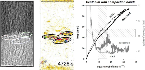
Figure 7 presents an image from CT scanning of the capillary test on one deformed sample, the location of acoustic emissions generated during triaxial loading and the capillary plots for the intact and deformed samples. Acoustic emissions clearly image the presence of compaction bands, which appear on the CT scan image as white linear sections: this is so because the density of the compaction bands increases due to porosity reduction induced by pore collapse and grain crushing. We calculated a reduction of about 15% in porosity within the bands compared to the intact rock. The capillary plots show a significant difference in the capillary rise kinetics, with a lower “A” parameter on the average for the deformed sample. Furthermore when the capillary front sweeps the compaction bands region (shaded area in Figure 7), a sharp increase in the radius of curvature is observed which shows that the water front flattens in the region where compactant deformation is concentrated.
6. Conclusion
We have investigated the influence of mechanical deformation on fluid flow using a combination of different techniques, among them x-ray CT scanning. Different porous rocks have been studied, and the results have been interpreted on a microstructural basis. It is shown that conducting capillary imbibition experiments under CT scanning is a powerful technique to image fluid flow patterns in reservoir rocks and how they are affected by deformation.
7. References
Baud, P., Vinciguerra, S., David, C., Cavallo, A., Walker, E., Reuschlé, T., “Compaction and failure in high porosity carbonates: mechanical data and microstructural observations”, Pure Appl. Geophys., vol. 166, 2009, p. 869-898.
David, C., Menéndez, B., Mengus, J.M., “Influence of mechanical damage on fluid flow patterns investigated using CT scanning imaging and acoustic emissions techniques”, Geophys. Res. Lett., vol. 35, 2008, doi:10.1029/2008GL034879.
Fortin, J., Stanchits, S., Dresen, G., Guéguen, Y., “Acoustic emission and velocities associated with the formation of compaction bands in sandstone”, J. Geophys. Res., vol. 111, 2006, doi:10.1029/2005JB003854.
Stanchits, S., Fortin, J., Guéguen, Y., Dresen, G., “Initiation and propagation of compaction bands in dry and wet Bentheim sandstone”, Pure Appl. Geophys., vol. 166, 2009, p. 843-868.
Van Geet, M., Swennen, R., Wevers, M., “Quantitative analysis of reservoir rocks by microfocus X-ray computerised tomography”, Sediment. Geol., vol. 132, 2000, p. 25-36.
Zinszner, B., Pellerin, F.M., A Geoscientist Guide to Petrophysics, Paris, Technip, 2007.