
3D Microanalysis of Geological Samples with High-Resolution Computed Tomography
ABSTRACT: During the last decade, Computed Tomography (CT) has progressed to higher resolution and faster reconstruction of the 3D-volume. More recently it has even allowed a three-dimensional look inside geological samples with submicron resolution. In recent years major steps in key hardware components like open microfocus or even nano-focus x-ray tube technology on the one side and the development of highly efficient and large flat panel detectors on the other, enabled the development of very versatile commercially available, high resolution laboratory CT systems. Electromagnetic focusing of the electron beam allows the generation of x-ray beams with an emission spot diameter smaller than 1 µm. The paper will showcase several geological applications performed with the nanotom, the first 180 kV nanofocus CT system with exceptional resolution less than 500 nm. The machine is capable of both high resolution nanofocus scans and high power mode scans (up to 15 W at the target), which can examine high-absorbing samples.
KEYWORDS: high resolution x-ray computed tomography, 3D micro-analysis, quantitative evaluation
1. Introduction
High resolution CT is nowadays a well established method for numerous industrial applications [Roth et al. 2003; Moller-Gunderson 2007; Nier et al. 2003] as well as for a wide range of research areas [Bonse 2004 and 2006]. During the last decade, Computed Tomography (CT) has progressed to higher resolutions and faster reconstructions of the 3D-volume. More recently it has even allowed a three-dimensional look into the inside of geological samples with submicron resolution.
CT for geological purposes can lead to a new dimension of understanding of the distribution of rock properties. In particular, spatial distribution of pores and pore-connections as well as cementation properties are of utmost importance in the evaluation of reservoir properties. The possibility to visualize a whole plug volume in a non-destructive way and to use the same plug for further analysis is undoubtedly currently the most valuable feature of this new type of rock analysis and will be a new area for routine application of x-ray CT in the near future.
The paper will outline the hard- and software requirements for high resolution CT. It will showcase several geological applications which were performed with the nanotom, the first 180 kV nanofocus CT system tailored specifically for highestresolution scans of samples up to 120 mm in diameter and weighing up to 1 kg with voxel-resolutions down to <500 nm (<0.5 microns).
2. High resolution CT
For many years, the only way to determine the interior structure of a sample with resolution in the sub-micron range was to section the part. This technique was not only time-consuming, but in this destructive process a valuable sample was lost. With advances in x-ray technology, however, this is no longer necessary. In many fields like biology, geology or engineering, CT with nanofocus x-ray sources allows the researcher to explore a sample’s structure at the sub-micron level. In recent years major steps in important hardware components like open microfocus or even nanofocus x-ray tube technology (the later was commercially introduced the first time by phoenix|x-ray in 2001) on the one side and the development of highly efficient and large flat panel detectors (by e.g. GE, Perkin-Elmer, Varian or Hamamatsu) using CCD or CMOS technology on the other, have allowed the development of very versatile and high resolution laboratory CT systems like the nanotom (see next section) which are commercially available. Electromagnetic focusing of the electron beam allows the generation of x-ray beams with an emission spot diameter down to well below 1 µm which is essential for CT examination with voxels-sizes in the sub-micron range. These characteristics with respect to spatial resolution principally allow CT measurements which valuably complement many absorption contrast setups at synchrotron radiation facilities [Withers 2007; Brunke et al. 2008].
Figure 1. Microfocus CT offers at resolutions of a few microns a wide application field for common 3D analyses. By use of nanofocus tube technology, CT systems are pushing forward into application fields that have been exclusive to expensive synchrotron techniques so far
3. Possible resolution and detail detectability
The requested resolution from the worldwide market increases year by year. Applications are in the fields such as materials science, micro mechanics, electronics and geology looking for the inner structures in the micron or even sub-micron range.
In order to cover the widest possible range of samples the CT system has to be equipped with an x-ray tube, manipulation stage and detector which allows in the sum a detail detectability in the sub-micrometer range. Therefore the nanotom is equipped with a 180 kV/15 W x-ray tube with adjustable spot size < 0.9 µm. Due to the penumbra effect the spot size predominates the image sharpness for extreme magnifications (for details see e.g. Brockdorf et al. 2008).
In Figure 2(a) the resolution capability of this high power nanofocus (HPNF) source is demonstrated. It shows that the 0.6 µm structure (line width) of the so called JIMA test pattern (Japan Inspection Instruments Manufacturers’ Association) can clearly be resolved. Figure 2(b) shows that for isolated structures of high absorbing material on a low absorbing substrate it is even possible to detect details of 0.5 µm size and below. The limit for this so called detail detectability for the HPNF tube lies at about 200 – 300 nm.
Figure 2. X-ray images of test patterns showing the capabilities of resolution and detail detectability of phoenix|x-ray’s high power nanofocus tube. In (a) the 0.6 µm line pair structure of the JIMA test pattern is clearly resolved. (b) shows the capability of the tube to resolve structures which are as small as 0.5 µm and below.
On the other hand the x-ray tube generates up to 15 W at the target and enables the penetration of samples like copper, steel or tin alloys thus allowing the analysis of electronic devices or high absorbing geological samples etc.
The manipulation stage is build from granite stone. Together with a high precision rotation unit samples can be moved and rotated with highest precision. On the detection side a 5-megapixel flat panel CMOS detector with a GOS scintillator deposited on a fiber optic plate is used. The pixel size of 50 µm and a 3-position virtual detector (i.e. 360 mm detector width) give rise to a wide variety of experimental possibilities.
4. Results
4.1. Oolithic carbonate: pore analysis
The first example shows an oolithic carbonate (sample diameter Ø 5 mm) scanned with 6 µm voxel size to extract information about the pore network (size of pores, connectivity, size of restrictions etc.). In Figure 3b is shown the quantitative pore analysis. Light colors are small pores whereas in black actually many interconnected pores are interpreted as one large pore. Analyzing the volume in quantitative manner yields extremely valuable information for the petrologists.
Figure 3 a+b. Tomographic slice (a) of an oolithic carbonate (Ø 5 mm). Pore analysis (b) give quantitative distribution of pore sizes (different gray levels)
4.2. Pyroclastic rock: pore network and surface extraction
As a next example a very porous pyroclastic rock (Ø 15 mm) from Etna (Sicily) has been examined at a resolution of 15 µm (see Figure 4) showing the possibility to study the spatial structure of the pore network. The resulting volume data can be used in general to produce extracted surface data for any CAD application and furthermore for FEM modeling for hydrogeological purposes.
Figure 4 a+b. 3D images of the reconstructed volume of a pyroclastic rock (view width: 13.5 mm). White areas indicate the pore network relevant for permeability (a), black are closed pores. In the right image (b) is shown the extracted surface as polygon model (black and gray means front and back surfaces).
4.3. Shell limestone: micro fossils
The last examples (Figures 5 and 6) are limestone samples called “tuffeau” largely used to build most of castles, cathedrals, churches and houses along the Loire valley (France). Due to weathering these buildings are often altered and eventually destroyed. Therefore it is important to understand the weathering mechanisms of building stones, i.e. to relate the microscopic mechanisms occurring at the pore scale (dissolution of minerals, transport, precipitation, etc.) to their consequences at the macro-scale (desquamation, powdering, etc.). Such a goal can be achieved with x-ray CT image analysis and numerical simulation of water flows within a realistic 3D image.
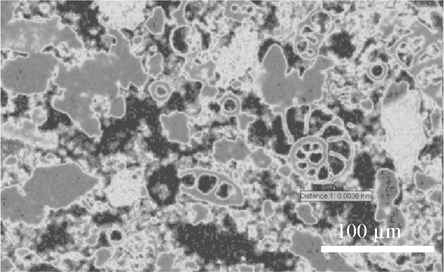
Samples were scanned with 1.2 µm voxel size and Figures 5 and 6 show impressively that such an investigation at pore scale is possible with no doubt and that evaluation of tomographic slices enables modeling at micron range.
Figure 5. Virtual cut through the 3D reconstructed volume of a shell limestone sample. The pore network is faded out and color coding is used to visualize different rock densities
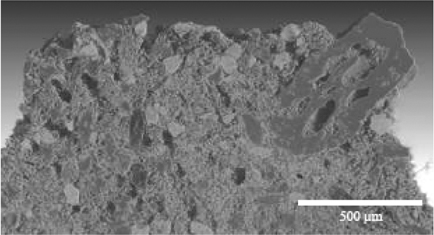
Figure 6. Zoom into a tomographic slice of a shell limestone sample to measure the wall thickness (3.6 µm) of a small ammonite
5. Summary
Since density transitions usually indicate boundaries between materials or phases, CT data is usually intuitive for geoscience professionals to evaluate. Due to the digital form, 3D data can be used for quantitative analysis as well as for a variety of measurement and visualization tasks.
Powerful software enables rapid reconstruction and visualization of the volume data allowing the user to extract and view internal features and arbitrary sectional views. The nanotom is the first nanoCT system featuring voxel resolutions of less than 500 nanometers (< 0.5 µm). The nanotom’s ability to deliver ultra highresolution images of any internal object detail at virtually any angle caters to even the most complex geological and petrological applications.
The nanotom was designed from the ground up with the primary goal of meeting the unique needs of high-resolution computed tomography and comes standard with a 180 kV high-performance nanofocus tube, 5-Megapixel digital detector, and 24 inch flat panel display. The 180 kV high power nanofocus tube enables the inspection of even the highest absorption materials such as metal, while the 5-Megapixel digital detector and a 3-position virtual detector enlargement enable the highest possible resolutions.
Today’s high-resolution x-ray CT with its powerful tubes and great detail detectability lends itself naturally to geological and petrological applications. Those include the interior examination and textural analysis of rocks and their permeability and porosity, the study of oil occurrences in reservoir lithologies, and the analysis of morphology and density distribution in sediments – to name only a few.
6. Acknowledgments
We thank E. Rosenberg, IFP, France and O.Rozenbaum, ISTO Orleans France.
7. References
Bonse, U. (Editor.), “Developments in X-Ray Tomography IV”, SPIE, Wellingham, (2004).
Bonse U., (Editor.), “Developments in X-Ray Tomography V”, SPIE, Wellingham, (2006).
Brockdorf, K. et al., “Sub-micron CT: visualization of internal structures” in Developments in X-ray Tomography VI, edited by Stuart Stock, Proceedings of SPIE, Vol. 7078, (2008).
Oliver Brunke, Kathleen Brockdorf, Susanne Drews, Bert Müller, Tilman Donath, Julia Herzen and Felix Beckmann: “Comparison between x-ray tube-based and synchrotron radiation-based µCT” in Developments in X-Ray Tomography VI, edited by Stuart R. Stock, Proceedings of SPIE, Vol. 7078, (2008).
Nier, E., Roth, H., “Analysis of Crimp Interconnections by Microfocus Computed Tomography”, QZ, 9, 916-918, (2003).
Moller – Gunderson, D., “When 2D X-ray isn’t enough”, SMT, 8, (2007).
Roth, H. Mazuik B., “What you can’t see can hurt you”, Quality Test and Inspection, 5, (2003).
Withers, P., “X-ray nanotomography”, Materials Today, 10(12), 26-34 (2007)