
Plugging Mechanism of Open-Ended Piles
ABSTRACT. The mechanism of the plugging phenomenon at the toe of vertically loaded open-ended piles was observed in this study by using a micro-focus x-ray CT scanner. The behavior of the surrounding ground at the pile toe is discussed based on the observation of the movement of iron particles, which were mixed into the sand and made layers in the sand layer. The movement of the sand particles was extracted from visualized x-ray CT data. In addition, the movement of the sand particles was extracted using the PIV (Particle Image Velocimetry) method. The CT images of the experimental results showed that the condition of the wedge formation below the open-ended pile was clearly different from that below the closed-ended pile. Although the penetration resistance of the open-ended pile and the closed-ended pile was similar, the movement of soil inside the open-ended pile was not stopped but restricted, as shown by intermittent increases and decreases in penetration resistance during pile penetration.
KEYWORDS: open-ended pile, plugging effect, bearing capacity, PIV, x-ray CT scanner
1. Introduction
For the past 50 years, the pile foundations of port facilities in Japan have been constructed by means of driving steel pipe piles into the ground. During these decades the diameter of piles and the embedded depth of piles have been enlarged. Although these changes have created considerable uncertainty about the toe-bearing capacity of piles, there have been insufficient studies on the bearing capacity of open-ended piles. This study focused on the mechanism of the plugging of open-ended piles to improve the accuracy of estimating the toe-bearing capacity of piles. The mechanism of the plugging at the toe of vertically loaded open-ended piles was observed in this study by using a micro-focus x-ray CT scanner (Kikuchi 2006). Three series of static penetration experiments with model piles were conducted. The model piles used in this study were open-ended piles and closed-ended piles. The behavior of the surrounding ground at the pile toe is discussed based on the observation of the movement of iron particles, which were mixed into sand and made layers in the sand layer. The movement of the sand particles was extracted from visualized x-ray CT data. In addition, the movement of the sand particles was extracted using the PIV (Particle Image Velocimetry) method.
2. Visualization of the plugging phenomenon
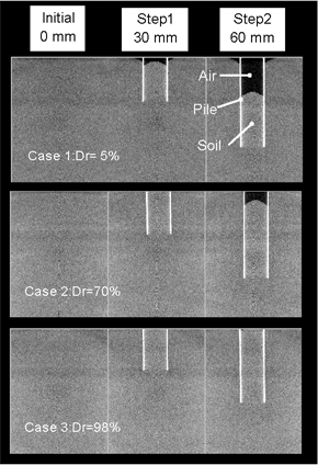
The first series of experiments was conducted to examine the plugging phenomenon. The piles used in this series were open-ended stainless steel piles with an outer diameter of 16 mm, a length of 80 mm, and a pile wall thickness of 0.3 mm. The container used was made of acrylic resin with an inner diameter of 85 mm and a height of 160 mm. The model ground was prepared with dry Toyoura sand (D50=0.2 mm, UC=1.6) by an air pluviation method. The thickness of the ground was 150 mm. Relative densities of the ground were set to 5, 70, and 98% by a vibration method. The pile penetrated the ground at a rate of 1 mm/min. The pile penetration experiment was conducted outside the x-ray CT scanner chamber. The penetration resistance and depth were measured at the pile top. When the pile had penetrated 30 and 60 mm, the load was released, the container was moved into the CT room, and x-ray CT scanning was performed.
The relationship between penetration resistance and depth is shown in Figure 1. Penetration resistance increases as the relative-density of the model ground increases.
Figure 2 shows a vertical section of CT images selected to obtain views through the central axis of the pile at each depth. The white lines are the pile, the gray area is the sandy ground, and the black area in the pile is air. The top of each CT image is the ground surface. It was observed that the ground surface, where the inner pipe pile was located, slid down with the pile in the test case of the low-density ground (Case 1, Dr=5%). Although it was speculated that the plug occurred at the pile toe, the penetration resistance did not increase. Although the ground surface did not slide down with the pile, the penetration resistance is relatively high in the test case of the high-density ground (Case 3, Dr=98%). These results showed that the occurrence of a ground invasion phenomenon into the pipe pile toe depends on the balance of ground reaction, the frictional resistance of the pile inside, and the weight of the soil. Therefore, the increment of resistance and the appearance of the plugging phenomenon do not have a one-to-one correspondence. In other words, there are some cases in which resistance occurred without the appearance of the plugging phenomenon.
Figure 1. Relationship between penetration resistance and depth
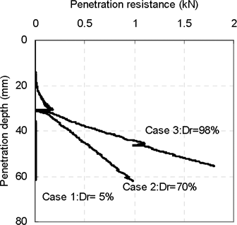
Figure 2. Vertical section of CT image.
3. Ground behavior around the pile toe
In this series of penetration experiments, a difference in the movement of the sand around the pile between closed-end and open-ended piles was observed. A new penetration apparatus was made to improve test accuracy. The dimensions of the model piles were 15 mm in diameter, 40 mm in length, and 1 mm in thickness for the open-ended piles. The material for the pile was aluminum. The container was made of acrylic resin, 100 mm in inner diameter and 440 mm in height. The sand used for the ground was Toyoura sand (0.2 mm of D50 and 1.6 of Uc). The model ground was 270 mm in thickness with a 65% relative density by air pluviation method. An overburden pressure of 2.5 kPa was applied with stainless steel balls (with a diameter of 2 mm).
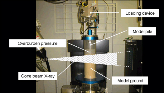
In order to investigate the movement of the ground from the x-ray CT results, a layer of iron particles (with a diameter of 0.3 mm) was used. The pile penetrated into the ground from the ground surface at a rate of 1 mm/min. The entire pile penetration experiment was conducted in the micro-focus x-ray CT scanner chamber, as shown in Figure 3. When the piles had penetrated to about 35 mm and 70 mm, the pile penetration was stopped, the load was released, and extension rods were added. To obtain test data, pile penetration was stopped at penetration intervals of 3 mm, and X-ray CT scanning was performed.
Figure 3. Penetration test in CT scanner chamber
The relationship between penetration resistance and depth is shown in Figure 4. A distinctive feature of the bearing capacity of the open-ended pile is that penetration resistance does not occur at the beginning of penetration, but decreases and increases in the middle of penetration. The increment of penetration resistance in both cases was almost equal after about 35 mm of penetration depth. This means that sufficient plugging of the open-ended pile may have developed. With the open-ended pile, resistance decreased and increased in the course of penetration at about 55 to 60 mm of penetration depth due to corresponding changes in the plugging effect. In other words, these results suggest that full plugging is not continuous but a plug is formed and broken repeatedly during pile penetration. This phenomenon was also reported through the research of a large-size laboratory experiment (Mizutani et al. 2003).
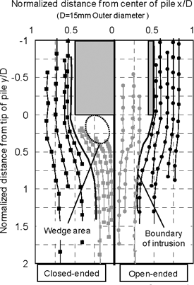
Figure 5 shows the movement of the particles during the pile penetration; the depth was from 42 mm to 81 mm, with points and lines extracted manually from the CT images. The points are the relative positions of the particles in the pile at each 3-mm step of penetration, and the lines are the particle routes. In the case of the closed-ended pile, the particles below the pile showed a tendency to be pushed to the outside of the pile toe. A clear wedge was constructed at this area, and the soil was unable to intrude there. Some of the particles below the pile were caught at the surface of the wedge, and some were discharged to the side of the pile at the edge and then moved along the pile. Because the wedge unified with the penetrating pile, the relative movement of soil at the surface of the wedge was greatly different. This implies that a shear zone may develop at the wedge surface. On the other hand, the particles below the pile toe were able to move upward and penetrate into the pile. The particles outside the pile were pushed to the outside of the pile toe.
Figure 4. Relationship between penetration resistance and depth
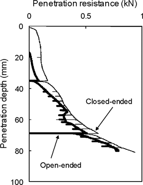
Figure 5. Movement of particles
4. Deformation analysis using PIV
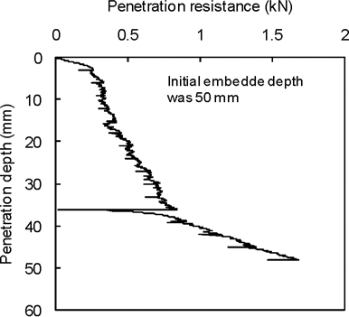
In order to examine in detail the ground behavior, the PIV method was applied to the CT images. This series of experiments was conducted to focus on the process of the plugging phenomenon evolution. In this series, the model pile was set up in the model ground at an initial penetration depth of 50 mm. The container and the loading device of this series of experiments were the same as the previous device. The pile used in this series was open-ended and 32 mm in diameter, 140 mm in length, and 1.5 mm in thickness. The pile was made of aluminum. The sand used was Souma sand #4 (0.7 mm of D50 and 1.6 of Uc). A larger-diameter model pile and larger-diameter sand were used to observe the ground behavior of the inner pipe pile by PIV in this series of experiments. The model ground was 270 mm in thickness with a 65% relative density by air pluviation method. An overburden pressure of 2.5 kPa was applied with stainless steel balls (with a diameter of 2 mm). The pile penetrated the ground at a rate of 1 mm/min from 50 mm to 98 mm in depth. The entire pile penetration experiment was conducted in the micro-focus x-ray CT scanner chamber.
The relationship between penetration resistance and depth is shown in Figure 6. Resistance occurred in the early stages of penetration in this experiment, because the soil had been packed in the pile at the start of penetration.
Figure 6. Relationship between penetration resistance and depth
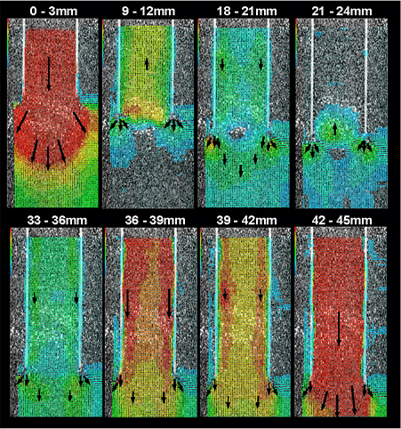
The vectors of ground displacement that were measured by the 2D PIV method are shown in Figure 7. This analysis was conducted on the plane of the central pile axis to minimize the disappearance of the particles observed in the analysis. The displacement vectors presented were measured between each 3 mm of penetration. Numbers shown at the top of each figure are the penetration depths for each figure. The pile is shown as two white lines and gradations show displacement of the ground. Since it is difficult to recognize the deformation of the ground in this figure, the major displacements are presented by arrows in the figure.
The soil inside of the pile and below the pile moved downward at penetration depths from 0 to 3 mm. This is because that inner soil put in the pile in the initial state created frictional resistance and made a plug. While the penetration depth increased slightly, the rate of resistance increment went down immediately at penetration depths from 3 to 6 mm. Low rates of incremental resistance were observed at penetration depths from 3 to 33 mm. Movements of the soil inside and below the pile were small at this penetration depth. The transient process of the plugging effect occurred in this stage. A relatively large movement of the soil inside of the pile was observed at penetration depths from 18 to 21 mm. But little movement was observed in the next stage of penetration. It was confirmed that repeated production and destruction of plugging occurred at these steps. The rate of resistance increment rose again after 33 mm of penetration. The displacement of the soil inside of the pile and below the pile became larger at penetration depths ranging from 30 to 36 mm; in particular, a downward movement of the soil existed and was maintained at penetration depths from 36 to 42 mm. A sufficient plugging effect occurred at this step. In this way, the relationship between penetration resistance and ground deformation was observed by using the PIV method.
Figure 7. Image of the ground displacement from CT images using PIV method. Arrows show the major direction and amount of displacement of the ground during the 3 mm penetration. The penetration depth is presented above each picture
5. Expected plugging mechanism of open-ended piles
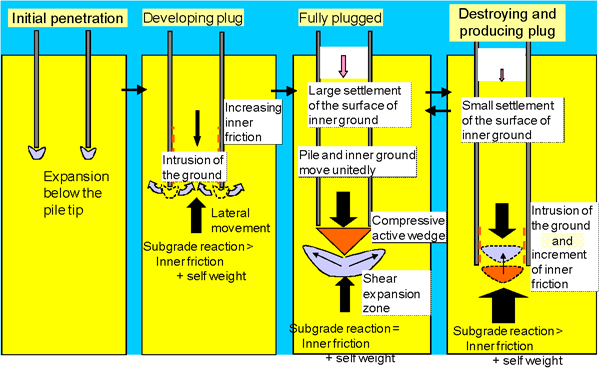
Based on these observations, the expected plugging mechanism is presented in Figure 8. The ground below the pile toe was deformed by pile penetration. The deformed and dilated soil intruded into the inside of the pile and it produced friction between the pile and the intruded soil. If the inner friction resistance and self-weight balanced with the bearing resistance of the ground below the pile toe, the plug was produced. Then, the area below the pile was compacted to form a soil wedge. However, if the bearing resistance of the ground below the pile overcame the resistance of the inner friction, the plug was destroyed and the wedge and the ground under the wedge intruded into the inside of the pile. This kind of mechanism in which the plug was produced and destroyed was repeated during the penetration of open-ended piles.
Figure 8. Expected plugging mechanism of open-ended pile
6. Conclusions
In this study, the behavior of the ground around a pile toe was analyzed based on a static penetration test. During the penetration test, the movement of the ground was observed using a micro-focus x-ray CT scanner. CT images of the experimental results showed that the condition of wedge formation below an open-ended pile was clearly different from that below a closed-ended pile. Although the penetration resistance of the open-ended pile and closed-ended pile was similar, the movement of soil inside the open-ended pile was not stopped but restricted, as shown by intermittent increases and decreases in penetration resistance during pile penetration. Conclusions about the expected plugging mechanism are presented in Figure 8.
7. References
Mizutani T., Kikuchi Y. and Taguchi H. “Cone Penetration Tests for the Examination of Plugging Effect of Open-ended Piles.” Proc. of IC on Foundations, BGA, 655-664, 2003.
Kikuchi Y. “Investigation of Engineering Properties of Man-made Composite Geo-materials with Micro-focus X-ray CT”. International Workshop on X-ray CT for Geomaterials-GeoX2006-, 53-78, 2006.