
Progress Towards Neutron Tomography at the US Spallation Neutron Source
ABSTRACT. The new US Spallation Neutron Source provides a world-class source of pulsed neutrons which may be useful for neutron tomography experiments in the geosciences. An instrument development team is proposing the construction of a tomography beamline at SNS, a project estimated at about $15M US. Progress on the technical, scientific, user community, and business cases is presented.
KEYWORDS: spallation neutron source, tomography, VENUS, geoscience
1. Introduction
The geosciences have been quick to use new imaging methods, both in the field and in the laboratory. As an example of the latter, we point to the success of the several tomography beamlines at the US Advanced Photon Source X-ray synchrotron (http://www.aps.anl.gov). While x-ray imaging is quite powerful, neutron imaging offers new options for geomaterials [Vontobel 2005]. At the time of writing, access to neutron imaging in the US is quite limited: the National Institute of Standards and Technology (http://physics.nist.gov/MajResFac/Nif/) and the University of California at Davis (http://mnrc.ucdavis.edu/imaging.html) have established user access programs and North Carolina State University and Indiana University are developing imaging facilities. The recent opening of the US Spallation Neutron Source (SNS, http://neutrons.ornl.gov/) at Oak Ridge National Laboratory in Tennessee may offer to the geosciences additional access with greatly improved imaging methods. In brief, the SNS experimental hall has room as of Fall, 2009, for a neutron tomography beamline and its neutron science advisory committee is considering the application for space on the floor. If laboratory space is granted, the next milestones are securing funds for an engineering design, then funds for construction. Altogether, the SNS neutron tomography beamline project may cost more than $15 M US and require several years to design and construct. At this writing, the project has a logo and a name, VENUS (VErsatile Neutron Imaging InstrUment at SNS).
The VENUS neutron tomography beamline design takes advantage of the unique pulse neutron flux produced at SNS. Members of the geoscience community are already familiar with time-of-flight methods as used in seismic imaging; many of the same issues – finite time duration of the initial pulse, propagation distances and media, and detector time resolution – are found in imaging with pulsed neutrons sources.
2. Spallation Neutron Source and proposed VENUS tomography beamline
In context, the US SNS is one of several pulsed neutron sources world-wide. In Oxfordshire, Great Britain, the ISIS-2 neutron source (http://ts-2.isis.rl.ac.uk/) will soon have the IMAT imaging beamline. The Japan Proton Accelerator Research Center (http://j-parc.jp/) is using the NOBORU beamline to evaluate tomography methods. The European Spallation Neutron Source (http://www.ess-neutrons.eu/) has recently completed the site selection process, opting for construction in Sweden. The China Spallation Neutron Source is proposed for construction in Dongguan, Gaungdong province [Wei 2009]. The above sources operate, or will operate, in a pulsed mode, typically 25 to 60 Hz. The SINQ neutron source at the Paul Sherrer Institute in Switzerland (http://sinq.web.psi.ch/) is a continuous neutron source creating neutrons via a spallation process.
In brief, a spallation neutron source starts with a near-GeV proton beam striking a high atomic number target. Each proton-nucleus collision generates 20-30 neutrons in the “spallation” process [Bauer 2001]. The high-energy neutrons are slowed with a moderator, often liquid hydrogen, to yield a flux with maximum intensity at 1-5 Å wavelength; see, for example Figure 15 in [Lu 2008] and note that 20 meV = 2.022 Å. The De Broglie equation allows one to convert neutron wavelengths into velocity as needed for time-of-flight measurements.
2.1. Properties of neutrons and time-of-flight imaging
Materials science is replete with imaging methods, ranging from optical, MRI, x-ray, positron, ultrasound, scanning probe microscopes to atom-scale aberration-corrected electron microscopy. In this context, neutrons are fascinating probes for several unique reasons:
– As neutral particles, their transmission through dense matter is exceptional. Neutrons can image structure inside solid lead objects.
– Neutrons have exceptional sensitivity to hydrogen, deuterium and other light atoms. One centimeter of water greatly attenuates 2 Å (20 meV, 2,000 m/s) neutrons.
– Neutrons in near thermal equilibrium with liquid hydrogen have wavelengths on the order of common crystallographic dimensions, so transmission through an object is sensitive to the various crystalline phases.
– Neutrons have a large magnetic spin moment, and are sensitive to magnetic fields and gradients.
Existing neutron tomography beamlines at reactor and continuous spallation sources have imaged samples spanning a huge range of science and culture. Excised rat lungs show changes as a function of inflation, key data needed for fundamental knowledge of human artificial ventilation systems. The images of trapped magnetic fields in superconducting lead provide tantalizing views of more applications to come in the field of high Tc materials [Kardjilov 2008; Dawson 2009; Strobl 2009]. Cultural heritage artefacts, as recovered from the depths of the Mediterranean Sea, have been examined to find what lies underneath the centuries-old encrustations [Kockelmann 2006].
Time-of-flight neutron imaging has been tested at the ISIS pulsed neutron source for metals [Kockelmann 2007]. Iron and copper were readily distinguished based upon their differing crystallographic d-spacings, when imaged with neutrons in the range of 1 to 5 Å. They found that in transmission-mode imaging, the crystallographic structure strongly affects the neutron scattering cross sections. Neutron scattering cross sections are usually tabulated for set velocity, typically 2,200 m/s which corresponds to 1.7982 Å or 25.299 meV. A few materials have been studied as a function of neutron energy, as shown in Figure 1. We see that crystalline materials show distinct “Bragg edges” where scattering cross sections change several-fold. Kockelmann et al. found that metal stress significantly affects the amplitude and sharpness of the Bragg edges. Figure 1 also shows the extremely large scattering cross section for liquid water, a fact that has led to experiments in wetting front imaging in geomaterials [Carminati 2007; Tullis 2007]. The data in Figure 1 are from “Experimental Nuclear Reaction Data” (EXFOR/CISISRS) web site (http://www.nndc.bnl.gov/exfor/exfor00.htm) and are identified in the database as: A1, 1958 R.J.Brown+; C, 1957 P.A.Egelstaff; Fe, 1982 J.A.Harvey+; P, 1952 W.W.Havens Jr; Ti, 1960 R.E.Schmunk+; and water, 1966 J.L.Russell Jr+.
Figure 1. Total neutron scattering cross-sections as a function of wavelength and as a function of flight time for a 25 m long beamline
The upper axis in Figure 1 indicates neutron travel time for a hypothetical 25 m flight path between the pulsed neutron source and the sample. The initial 2 Å neutron pulse as it enters the flight tube has a time-width on the order of 20 µs. Neutron detectors with equivalent time resolution have recently become available [Dangendorf 2009; Tremsin 2009]. Flight tubes shorter than 25 m will, in principle, benefit from higher neutron flux (less 1/r2 losses) while longer tubes will yield better wavelength accuracy and allow for larger samples (more time evolution relative to the initial pulse; more space in the experimental hall).
2.2. Workshops and user community input
Based on attendance at recent workshops held at SNS, VENUS is already appreciated by many. The October 2006 “Imaging and Neutrons” workshop (http://neutrons.ornl.gov/workshops/ian2006/) drew 200 participants, more than for any other kick-off workshop for an SNS beamline. The VENUS Instrument Development Team (IDT) was created at the 2006 workshop and then drafted a Letter-of-Intent for the ORNL neutron science advisory committee. The VENUS LoI was approved with its first reading at the November 2008 meeting. To refine the LoI, another workshop was held in November 2008 (http://neutrons.ornl.gov/conf/nisns2008/). Comments from the workshops, the IDT, and the science advisory committee have lead to the following conceptional design for VENUS.
2.3. Conceptional design of the VENUS beamline
Relative to existing beamlines at reactor and continuous spallation sources, the proposed VENUS neutron tomography beamline will be a next-generation instrument. Key features include:
– Neutrons from the pulsed source will be observed with time-of-flight (TOF) strategies. This gives us access to a wide neutron energy range in a very short time. TOF may also offer new strategies for imaging scattered neutrons, especially in thicker samples.
– The neutron energy range is particularly broad, with ∼23 MeV spallation neutrons in a 695 ns time window as well as the moderated 0.5 Å (7912 m/s, 327 meV) to 10 Å (396 m/s, 0.818 meV) originating from an approximately 20 to 40 µs time window.
– The pulsed beam allows synchronization with repetitive processes for stroboscopic imaging.
– The wave-particle dualism allows one to treat the neutron as a particle having a defined mass or to regard it as a propagating wave with corresponding amplitude and wavelength. In conventional radiography the image formation is given in terms of attenuation of the propagated neutron beam. In the case of phase-contrast imaging, the phase variations obtained by the propagation of coherent radiation are transformed to intensity variations. Phase-contrast imaging with neutrons was reported by implementing a free-path propagation technique where a beam with high order of spatial coherence was used [Allman 2000]. A new technique using spatial gratings was presented recently [Pfeiffer 2006] where the low beam intensity problems of the former methods are partially solved.
– The spin rotation of the component perpendicular to the magnetic field B can be described by the spin phase
[1] ![]()
where γ is the gyromagnetic ratio of the neutron (−1.8324×10⁸ rad s−1 T−1) and m is the mass and λ the wavelength of the neutron. The total spin rotation in simple monochromatic transmission imaging can be deduced with an uncertainty with respect to the periodicity of the cosine function, if no other a piori knowledge about the sample can be used. In contrast, a time-of-flight approach, could overcome this drawback efficiently, due to the additional wavelength-dependent information [Strobl 2009].
– At this point, it is important to discuss the relative merits of monochromatic reactor sources versus time-of-flight spallation sources. Time-of-flight allows the experimentalist to adjust data collection for either very fine or very broad wavelength ranges; a monochromator generally has a fixed bandwidth. Data from FRM II [Schulz 2009] and SNS flux simulations show that FRM and SNS have equivalent data acquisition rates when VENUS is operated in a 10-point multiplex mode for each neutron pulse (assumes Δλ=0.1 Å and a bandwidth of 1 Å). The VENUS advantage increases with bandwidth and/or larger Δλ.
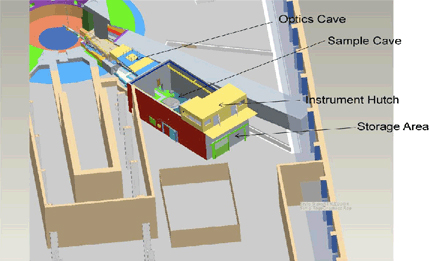
Combining all of these thoughts has lead to a preliminary design which was presented to the SNS neutron science advisory committee as part of a beamline letter-of-intent (approved). A sketch of the proposed VENUS beamline is shown in Figure 2. The sketch is based on a flight tube of 15 to 20 m with an upstream optics cave that may contain optional neutron focusing optics, gratings for phase contrast imaging, or spin-polarizers for magnetic field imaging. Not visible in the sketch are upstream collimators to establish beam quality, gamma ray filter, neutron shutter, and bandwidth choppers to prevent overlap from multiple neutron pulses at the 60 Hz SNS source. The experimental hutch is designed to accommodate large samples and ancillary sample environmental equipment.
The design, funding and construction of such a large instrument is challenging. The VENUS Instrument Development Team consists of 30+ members from research facilities, industry, and academia across the world (see SNS workshop web sites). The science and business cases continue to evolve and user input is welcomed.
Figure 2. The VENUS beamline as proposed in the letter of intent
3. Acknowledgments
The author would like to thank Drs. Eberhard Lehmann and Burkhard Schillinger and their groups at the Paul Scherrer Institute and FRM II, respectively, for introducing the author to the technique of neutron tomography.
4. References
Allman, B. E., McMahon, P. J., Nugent, K. A., Paganin, D., Jacobson, D. L., Arif, M. and Werner, S. A., “Imaging - Phase radiography with neutrons”, Nature, vol. 408, 2000, p.158-159.
Bauer, G. S., “Physics and technology of spallation neutron sources”, Nuclear Instruments & Methods in Physics Research Section a-Accelerators Spectrometers Detectors and Associated Equipment, vol. 463, 2001, p.505-543.
Carminati, A., Kaestner, A., Ippisch, O., Koliji, A., Lehmann, P., Hassanein, R., Vontobel, P., Lehmann, E., Laloui, L., Vulliet, L. and Fluhler, H., “Water flow between soil aggregates”, Transport in Porous Media, vol. 68, 2007, p.219-236.
Dangendorf, V., Bar, D., Bromberger, B., Feldman, G., Goldberg, M. B., Lauck, R., Mor, I., Tittelmeier, K., Vartsky, D. and Weierganz, M., “Multi-Frame Energy-Selective Imaging System for Fast-Neutron Radiography”, IEEE Transactions on Nuclear Science, vol. 56, 2009, p.1135-1140.
Dawson, M., Manke, I., Kardjilov, N., Hilger, A., Strobl, M. and Banhart, J., “Imaging with polarized neutrons”, New Journal of Physics, vol. 11, 2009, p.art. no. 043013.
Kardjilov, N., Manke, I., Strobl, M., Hilger, A., Treimer, W., Meissner, M., Krist, T. and Banhart, J., “Three-dimensional imaging of magnetic fields with polarized neutrons”, Nature Physics, vol. 4, 2008, p.399-403.
Kockelmann, W., Frei, G., Lehmann, E. H., Vontobel, P. and Santisteban, J. R., “Energy-selective neutron transmission imaging at a pulsed source”, Nuclear Instruments & Methods in Physics Research Section a-Accelerators Spectrometers Detectors and Associated Equipment, vol. 578, 2007, p.421-434.
Kockelmann, W., Siano, S., Bartoli, L., Visser, D., Hallebeek, P., Traum, R., Linke, R., Schreiner, M. and Kirfel, A., “Applications of TOF neutron diffraction in archaeometry”, Applied Physics a-Materials Science & Processing, vol. 83, 2006, p.175-182.
Lu, W., Ferguson, P. D., Iverson, E. B., Gallmeier, F. X. and Popova, I., “Moderator poison design and burn-up calculations at the SNS”, Journal of Nuclear Materials, vol. 377, 2008, p.268-274.
Pfeiffer, F., Grunzweig, C., Bunk, O., Frei, G., Lehmann, E. and David, C., “Neutron phase imaging and tomography”, Physical Review Letters, vol. 96, 2006, p.art. no. 215505.
Schulz, M., Böni, P., Calzada, E., Mühlbauer, M. and Schillinger, B., “Energy-dependent neutron imaging with a double-crystal monochromator at the ANTARES facility at FRM II”, Nuclear Instruments & Methods in Physics Research Section a-Accelerators Spectrometers Detectors and Associated Equipment, vol. 605, 2009, p.33-35.
Strobl, M., “Future prospects of imaging at spallation neutron sources”, Nuclear Instruments & Methods in Physics Research Section a-Accelerators Spectrometers Detectors and Associated Equipment, vol. 604, 2009, p.646-652.
Strobl, M., Kardjilov, N., Hilger, A., Jericha, E., Badurek, G. and Manke, I., “Imaging with polarized neutrons”, Physica B, vol. 404, 2009, p.2611-2614.
Tremsin, A. S., McPhate, J. B., Vallerga, J. V., Siegmund, O. H. W., Hull, J. S., Feller, W. B. and Lehmann, E., “Detection efficiency, spatial and timing resolution of thermal and cold neutron counting MCP detectors”, Nuclear Instruments & Methods in Physics Research Section a-Accelerators Spectrometers Detectors and Associated Equipment, vol. 604, 2009, p.140-143.
Tullis, B. P. and Wright, S. J., “Wetting front instabilities: a three-dimensional experimental investigation”, Transport in Porous Media, vol. 70, 2007, p.335-353.
Vontobel, P., Lehmann, E. and Carlson, W. D., “Comparison of X-ray and neutron tomography investigations of geological materials”, IEEE Transactions on Nuclear Science, vol. 52, 2005, p.338-341.
Wei, J., Chen, H. S., Chen, Y. W., Chen, Y. B., Chi, Y. L., Deng, C. D., Dong, H. Y., Dong, L., Fang, S. X., Feng, J., Fu, S. N., He, L. H., He, W., Heng, Y. K., Huang, K. X., Jia, X. J., Kang, W., Kong, X. C., Li, J., Liang, T. J., Lin, G. P., Liu, Z. N., Ouyang, H. F., Qin, Q., Qua, H. M., Shi, C. T., Sun, H., Tang, J. Y., Tao, J. Z., Wang, C. H., Wang, F. W., Wang, D. S., Wang, Q. B., Wang, S., Wei, T., Xi, J. W., Xu, T. G., Xu, Z. X., Yin, W., Yin, X. J., Zhang, J., Zhang, Z., Zhang, Z. H., Zhou, M. and Zhu, T., “China Spallation Neutron Source: Design, R&D, and outlook”, Nuclear Instruments & Methods in Physics Research Section a-Accelerators Spectrometers Detectors and Associated Equipment, vol. 600, 2009, p.10-13.