Computation of Aggregate Contact Points, Orientation and Segregation in Asphalt Specimens Using their X-ray CT Images
ABSTRACT. In this paper, image processing and analysis methods are presented to extract the individual aggregate properties from the x-ray CT images of asphalt specimens. First, a technique was presented (and validated) to segment the clustered aggregates due to elevated pixel intensities near the aggregate-to-aggregate contacts in the image. Once the aggregates were segmented, aggregate-to-aggregate contact points, 3D orientation and segregation of aggregates were analyzed for asphalt specimens compacted at different levels.
KEYWORDS: x-ray CT, aggregate, asphalt mixture, image processing
1. Introduction
Internal structure characteristics related to the aggregate skeleton significantly influence the long-term performance and sustainability of asphalt pavements. Packing and compaction of aggregates within asphalt mixtures can be very important for the overall performance of the system. However, in asphalt mixtures, direct quantification of internal packing characteristics of aggregates in 3D has been very limited. One method of direct quantification of 3D microstructures is through imaging techniques such as x-ray Computed Tomography (CT). Previous studies have utilized x-ray CT to quantify the air void distribution (Masad et al. 2002; Tashman et al., 2002), aggregate homogeneity (Azari et al., 2005), and pore-scale fluid flow modeling of asphalt mixtures (Kutay et al. 2007a; Kutay and Aydilek 2007b). However, the compacted characteristics of individual aggregates such as location, orientation, and aggregate-to-aggregate contact points have rarely been successfully quantified. One of the main challenges in processing and analyzing the x-ray CT images was the segmentation of aggregates that are in close proximity to other aggregates, which causes clustering of aggregates after thresholding and labeling operations (Figure 1). In this study, an image processing procedure was followed to overcome this shortcoming. In addition, packing/compaction characteristics of aggregates including the aggregate-to-aggregate contact points, 3D orientation angles and segregation were studied for asphalt mixtures with different compaction levels.
2. Materials and characteristics of the x-ray CT equipment
In order to illustrate the aggregate packing characteristics computed by the image analysis algorithms presented in this paper, two asphalt mixture specimens compacted at 30 (low compaction level, labeled N30) and 160 (high compaction level, labeled N160) number of gyrations were utilized. Both specimens were of the same mix design and were compacted using the Superpave Gyratory Compactor. The specimens were scanned at the x-ray CT equipment available at the Federal Highway Administration (FHWA) Turner-Fairbank Highway Research Center (TFHRC). The x-ray CT device had a 420 keV continuous x-ray source and a linear array detector of 512 channels. The diameters of the specimens were 150 mm. The minimum aggregate size that can be measured using the x-ray CT technique is highly dependent on the spatial resolution of the images. In this study, the resolution of the resulting images, corresponding to 150 mm diameter specimens, were approximately 0.3 mm/pixel in the horizontal direction and 0.8 mm/pixel in the vertical direction. Assuming that approximately 8-10 voxels are needed to be able to segment an aggregate, the minimum size of the aggregate that can be measured was of about 3 mm. This size can be reduced if smaller size specimens are scanned.
3. Image processing procedure to segment aggregates
In dense asphalt specimens, where the aggregates are in close proximity to each other, the elevated pixel intensities near aggregate-to-aggregate contacts result in multiple aggregates being incorrectly considered and labeled as a single particle. As seen in Figure 1b and 1c, after thresholding and labeling operations, the regions 11 and 13 are actually composed of two or more aggregates, yet labeled as a single entity when the traditional algorithm is applied.
Figure 1. Illustration of traditional binary thresholding and labeling; (a) original grayscale image, (b) thresholded binary image, and (c) labeled image

In order to eliminate the problem of clustering of aggregates, several different image processing methods were investigated. The set of image processing steps that were found to be successful in separating the aggregates is illustrated in Figure 2. In summary, the steps are as follows:
1. Filter the image using a Gaussian filter to eliminate most of the noise (Figure 2b). The size and standard deviation of the Gaussian filter can be varied based on the quality of the image or the material composition of the aggregates.
2. Apply the H-maxima transform to suppress all the maxima in the grayscale image whose height is more than a selected scalar value. The goal of this step is to eliminate the variation in pixel intensity of the aggregates so that they have uniform gray value. H-maxima transform allows this without changing the intensities of the darker (i.e. lower intensity) regions (Figure 2c). This step is very important for a successful watershed transformation.
3. Invert the image and perform watershed transformation where the image is divided into unique watershed regions and their boundaries are determined (Figure 2d).
Figure 2. Image processing steps for separation of aggregates
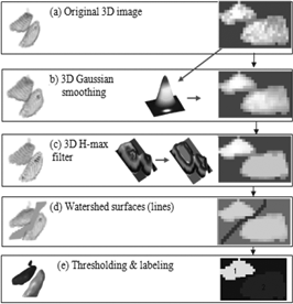
Figure 3. Original and image-based back-calculated gradations
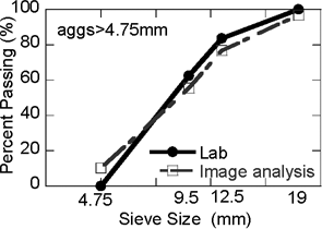
These steps were implemented in Matlab® and utilized several sub-functions available in the Image Processing Toolbox. The algorithm was validated by calculating the aggregate gradation from the x-ray CT images of a specially prepared asphalt mixture whose aggregate gradation is known. As shown in Figure 3 the gradation of the specimen measured in the lab matches reasonably well with the gradation calculated from the analysis of x-ray CT images. It should be noted that, during image analysis, the individual aggregates were classified into each sieve size using their sphere-equivalent diameter, i.e. Deq = 2(3Vag/4π)1/3, where Vag is the volume of the aggregate.
4. Calculation of aggregate-to-aggregate contact points
Contact points were calculated using the surface voxels of each aggregate. Surface voxels were isolated from the rest of the voxels using the following rule: a voxel is part of the surface if it is non-zero and it is connected to at least one zero-valued pixel. Then, the minimum distance between the surfaces of neighboring aggregates was calculated (Figure 4). If this distance was less than a pre-selected surface distance threshold (SDT) value, the aggregates were assumed to be incontact.
An important component of the contact point calculation is identifying neighboring aggregates. This step is crucial for the computational efficiency of the algorithm. Otherwise, the surface voxels of all aggregates will be searched, which would increase the computation time significantly. Neighboring aggregates were detected using their centroids (xc, yc, zc), equivalent diameters (Deq), and the SDT value. Before the contact point search, the distances between the centroids of all aggregates were computed. If the distance between any two aggregate was less than the sum of the equivalent diameters of the aggregate pair plus the SDT value, they were considered “neighbors”.
Figure 4. Number of contact points as a function of SDT
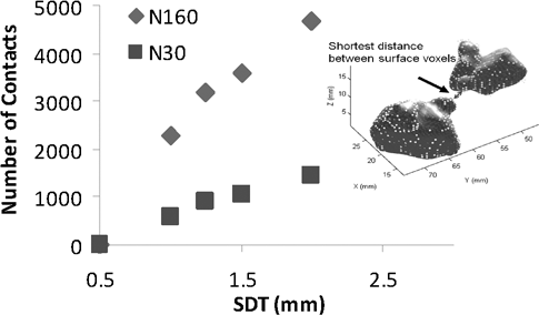
Figure 4 shows the variation of number of contact points as a function of the SDT values. It can be observed from Figure 4 that the number of contact points varies greatly with the selected Surface Distance Threshold (SDT) value. In addition, the number of contact points is significantly higher for N160 (high compaction) than for N30 (low compaction) at all SDT values. This was expected since the aggregates get close to each-other with additional compactive effort. It should be noted that the selection of SDT value is important for the quantity of contacts. However, regardless of the selected SDT value, the number of contact points is a very good indicator of compactive effort in different asphalt mixtures.
5. Calculation of the orientation of aggregates
First step in computation of the orientation is the determination of the major principal axis (Dmax) of an aggregate. The Dmax was determined using the formula:
[1] ![]()
where xi, yi and zi are x-, y- and z-coordinate of a surface voxel with respect to the centroid of the image, x−i, y−i and z−i are x-, y- and z-coordinate of a surface voxel (with respect to the centroid of the image) at the opposite side of a line going through the centroid of the aggregate (Figure 5 a).
Figure 5. (a) The illustration of the coordinates used in the Dmax and orientation calculation and (b) the orientation angles α, β and θ
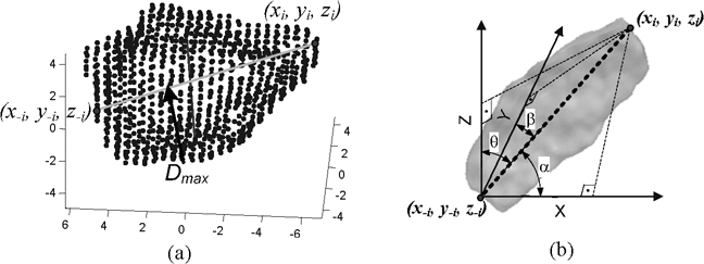
Once the Dmax was determined, the orientation angles were computed using the surface voxels in the opposite ends of the Dmax line as follows:
[2] ![]()
where α, β and θ are the orientation angles of the principal axis with respect to the x-, y- and z- axes, respectively, as shown in Figure 5b. Physically, these angles represent how the major principal axis is oriented with respect to the x-, y- and z-axes. For example, if an aggregate has θ = 90, it is lying on x-y plane. If both θ = 90, and α =90, then the aggregate is parallel to the y-axis.
Figure 6. Aggregate orientation distribution in specimens (a) N30 and (b) N160
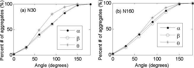
Figures 6a and 6b show the cumulative distribution of the α, β and θ orientation angles for specimens N30 and N160, respectively. For random orientation distribution of an angle, this graph should be linear as in the case for angles α and β. As shown in Figure 6a, in specimen N30, the distribution of the angle θ is not uniform. The maximum deviation of the curve (of angle θ) from the uniform distribution is at around 90 degrees. This indicates that the number of aggregates with θ ∼ 90 is larger than the other angles. It should be noted that the z-axis is the direction of compaction. This indicates that the maximum principal axis of the majority of aggregates lie on x-y plane (i.e. perpendicular to the direction of compaction). On the other hand, Figure 6b shows that, at higher compaction level (N160), the curve for the angle θ gets closer to the uniform distribution. This may indicate that the aggregates become more randomly distributed as the compaction level increases.
6. Calculation of the segregation of aggregates
The segregation of aggregates in the specimens was quantified by dividing the specimen into different zones (groups) and calculating the number of aggregates in each group for each size. Since the specimens used in this study were cylindrical, radial and vertical segregation was investigated. For radial segregation, the 3D x-ray CT image was divided into three groups as shown in Figure 7a.
Figure 7. Illustration of segregation groups for (a) radial and (b) vertical segregation
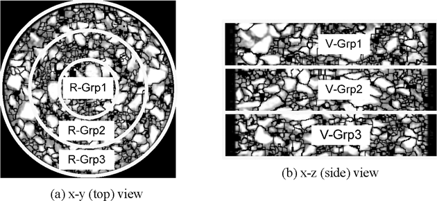
In this figure, Group-1 is a cylinder with radius Rspec/3, Group-2 is a ring shape with inner radius Rspec/3 and outer radius 2*Rspec/3, and Group-3 is a ring shape with inner radius 2Rspec/3 and outer radius Rspec. The Rspec is the full radius of the specimen. Similarly, the vertical segregation was quantified by dividing the specimen into three zones in the vertical direction as shown in Figure 7b. In Figure 7b, each group is the 1/3 of the height of the specimen. It should be noted that image slices shown in Figure 7 are the processed images, showing the watershed lines separating the aggregates from each other.
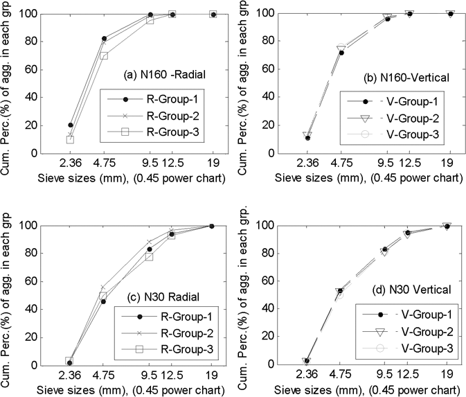
Figure 8 shows the results of vertical and radial segregation analyses of specimens N30 and N160. Figure 8 can simply be interpreted as the aggregate gradation in each zone (i.e. group). As shown in Figures 8b and 8d, there seems to be no segregation in the vertical direction. On the other hand, as shown in Figures 8a and 8c, there are slight differences in gradation in radial groups (Figure 7a). In Figure 8a, the specimen N160 seems to have coarser gradation in Group 3 (outermost ring) as compared to the other groups. In specimen N30, as shown in Figure 8c, the Group 2 seems to have slightly finer gradation than the other groups.
Figure 8. Radial (a & c) and vertical (b & d) segregation of the aggregates
7. Conclusions
This paper presented several image processing and analysis procedures to extract aggregate packing characteristics in asphalt mixtures using x-ray CT images. First, the problem of touching-aggregates was addressed through an image processing procedure that utilizes Gaussian filtering, regional maxima filtering and watershed transformation. Once the aggregates are separated (i.e., each aggregate occupy distinctly separate regions), aggregate-to-aggregate contact points, 3D orientation angles and segregation (i.e. gradation of aggregates at certain zones of the specimen) was computed. Based on the foregoing, the following conclusions were drawn:
- The image processing technique presented in this paper can successfully be used to separate aggregates in compacted asphalt mixtures. The same technique can also be used in concrete images.
- It was observed that the number of contact points of aggregates in asphalt mixture vary greatly with the selected Surface Distance Threshold (SDT) value. However, regardless of the selected SDT value, the number of contact points is a very good indicator of compactive effort in different asphalt mixtures.
- Orientation analyses revealed that maximum principal axis of the majority of aggregates lie on x-y plane (i.e. perpendicular to the direction of compaction) in specimens analyzed in this study.
- Segregation analyses, comparing aggregate gradations at different zones of the specimen, indicated no segregation in vertical direction. Whereas, there was indications of segregation in radial direction in specimens (which were compacted using the gyratory compactor).
8. References
Kutay, M.E., Aydilek, A.H., Masad, E., and Harman, T. (2007a), “Computational and Experimental Evaluation of Hydraulic Conductivity Anisotropy in Hot Mix Asphalt”, International Journal of Pavement Engineering, vol. 8 (1): 29-43.
Kutay, M.E., and Aydilek, A.H. (2007b), “Dynamic Effects on Moisture Transport in Asphalt Concrete”, ASCE Journal of Transportation Engineering, vol. 133 (7): 406-414.
Masad, E., Jandhyala, V.K., Dasgupta, N., Somadevan, N. and Shashidhar, N. (2002), “Characterization of air void distribution in asphalt mixes using x-ray computed tomography”, Journal of Matls. in Civil Eng., vol. 4 (2): 122-129.
Tashman, L., Masad, E., D’angelo, J., Bukowski, J. and Harman, T. (2002), “X-ray tomography to characterize air void distribution in Superpave gyratory compacted specimens”, International Journal of Pavement Engineering, vol. 3 (1), pp. 19-28.
Azari, H., McCuen, R., and Stuart, K. (2005), “Effect of Radial Inhomogeneity on Shear Properties of Asphalt Mixtures”, Journal of Matls. in Civil Eng., vol. 17 (1): 80-88.
