
WHEN IT COMES TO character animation, the Bone tool can be quite useful. Applying bones to a character is often referred to as “rigging”. The first step is designing the character so that each body part is a separate object that can be articulated with a bone armature. The next step is adjusting the rotation and translation of each bone to limit how much they rotate and move along its X and Y axes. This is the most critical detail of the Bone tool because you don’t want the character’s limbs and joints to bend past their anatomical limits.
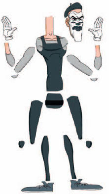
1 Here’s the exploded view of the character and all its various body parts. Notice the arms and legs have elbows and knee caps to help eliminate gaps between objects when rotated.
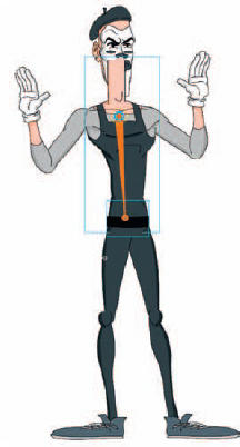
2 The first bone is the root (sometimes referred to as a “parent” bone) in the chain. It seems logical to assign the main torso or chest object to this root bone. Here I have linked the torso and the pelvis objects together.
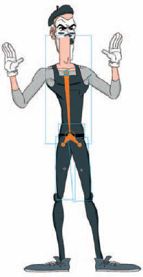
3 Working downwards, I branch off from the pelvis symbol to both upper leg symbols. The pelvis symbol is important because it increases articulation while hiding any potential gaps between the legs and torso when rotated.
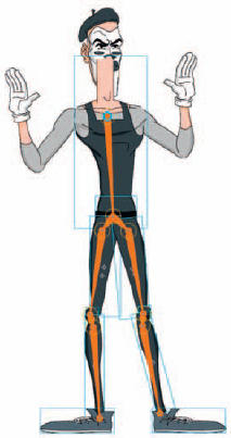
4 The lower portion of the character rigging is complete. Bones were added from the upper leg symbols to each knee cap, then to each lower leg symbol and then ultimately each foot symbol.
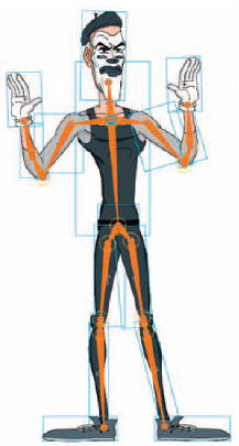
5 Continuing from the root bone, connect both upper arms, elbows, forearms and hands. The final step in the armature is adding the last bone from the root to the head symbol.
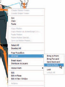
6 When adding bones to symbols, the stacking order can often change based on the original design. To correct this, right-click over the necessary symbols, go to Arrange and then select the appropriate action.
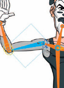
7 Next, constrain the rotation and translation for each bone. Select a bone and in the Properties panel check the Constrain boxes for each of these properties and use the hot text sliders to set each value.
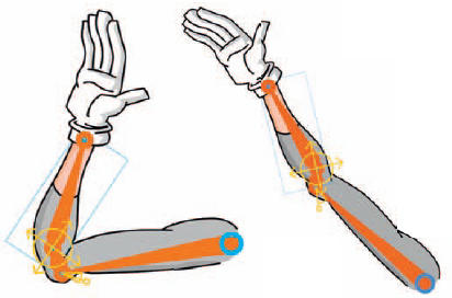
8 By default, bone translation for the X and Y axes are disabled. When each translation is enabled, a bone can move along the X-or Y-axis to an unlimited degree. Select Enable in the Joint: X Translation or Joint: Y Translation section in the Property panel. A two-headed arrow appears perpendicular to the bone on the joint to indicate that X-axis motion is enabled. Adjusting the minimum and maximum values helps you control the position of the bone, especially when rotation is disabled as well.
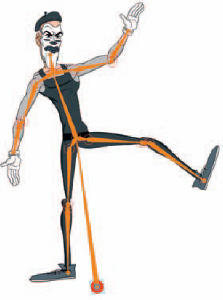
9 Another technique I have been playing with is having the root bone start on a “ghost” symbol. A ghost symbol is not part of the character design. Its sole purpose is to separate the root bone from the actual character for even more articulation.


Hot Tip
In the “Chapter 14” folder on the source CD I included “mime_bones.fla”. You are welcome to open it and play around with the Mime character and its bone armatures. I included the two different techniques displayed here (with and without the “ghost” root symbol). To prevent the ghost symbol from being visible on export, simply edit the symbol by deleting the object inside it (do not delete the instance of the symbol).
![]()