
316 Design of CMOS Millimeter-Wave and Terahertz Integrated Circuits
0 50 100 150 200 250 300
-3
-2
-1
0
1
2
miu
Frequency (GHz)
re(miu)
im(miu)
0 50 100 150 200 250 300
-25
-20
-15
-10
-5
0
S(2,1)
Frequency (GHz)
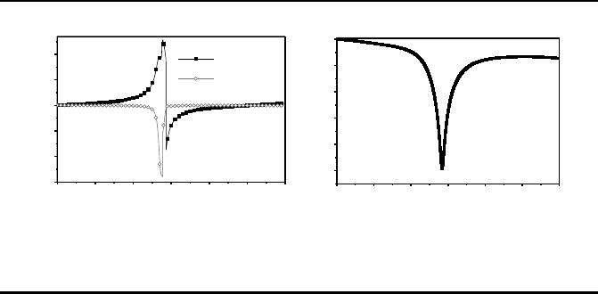
(a) (b)
Figure 14.11: (a) The simulated body current distribution of the
single SRR resonator at magnetic reso nance frequency (140 GHz),
and (b) Figure 14.4: the simulated body current d istribution o f the
stacked SRR resonator at magnetic resonance frequency (140 GHz).
large power at the receiver side, but their data rates are only limited to multi-
Gbps. The performance of the proposed SRR-based modulator will be evalu-
ated by modulation of 20Gbps data in the next section.
The stacked SRR and the SRR-based modulator are designed in standard
65nm 1P9M CMOS technology. The silicon substrate is lossy with 70-S/m
conductivity, while the stacking SRR and the proposed modulator are con-
structed using the top-most two copper metals owing a thickness of 0.9µm
and 3.3µm, respectively. Here, the EM software HFSS is used for simulation.
An incident EM wave polarized to the x direction (shown in Figure 14.8)
excites the structure , and the boundary condition set as open to simulate
the real space. The boundary conditions are at large distance from the metal
structure to avoid significant reflections.
To investigate how the induce d cur rent is suppressed, Figure 14.10(b) il-
lustrates the body curre nt distribution in the upper SRR unit-cell. Now the
currents on two stacking SRR unit-cells flow in the clockwise direction. Thus,
the overall magnetic field is perpendicular to the SRR structure is reinforced
by the summation of the magnetic field generated in e ach SRR unit-cell, which
leads to a significant increase of the negative permeability effect. Meanwhile,
the induced currents in each unit-cell are mutually compensated and the re-
sulting current density is strongly suppressed as compared to the case of single
SRR shown in Figure 14.10(a). As a result, the current crowding effect is o mit-
ted, and the radiation loss is significantly suppressed as well. The ma gnetic
metamaterial property is further confirmed by Figure 14.11. The parameter
extraction is done by the conversion fro m S parameters [315]. It shows that
near the magnetic resonance freque nc y, the effective permeability has a nar-
row nega tive region, at which a sharp attenuation takes place. Note tha t while
..................Content has been hidden....................
You can't read the all page of ebook, please click here login for view all page.