
Antenna 199
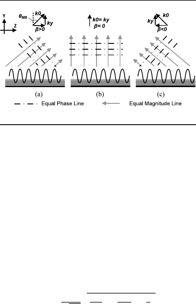
Figure 8.1: Operation diagram of leaky wave antenn a: (a) β > 0, (b)
β = 0, and (c) β < 0.
8.3 Circularly Polarized SIW Antenna
SIW structures have been recently explored for the design of high-quality fa c-
tor (Q) passive devices in b oth mm-wave and sub-THz regions [233, 234, 23 5].
SIW can be regarded as a dielectric-filled rectangular waveguide with sur-
rounding walls and metal layers on the top and bottom surfaces, which
leverages the advantages of both planar transmission line and non-planar
waveguide with lowe r loss and wide-band performance in a miniaturized cavity
for on-chip antenna design.
SIW antennas designs are proposed in both PCB scale [2 33] and chip
scale [234] with a wide bandwidth and a hig h gain. In [234], a 400GHz linear
polarized on-chip SIW antenna is demonstrated in SiGe process with -0.55dBi
gain and 7.8% relative bandwidth. However, its dimension has to satisfy an
equivalent electrical length of λ/2, which should be further miniaturized when
designed on-chip.
A compact circular-polarized SIW antenna design is designed in the CMOS
process with corner slots, of which the geometrical configuration is illustrated
in Figure 8.2. The operating frequency of a SIW antenna is determined by
the cavity dimension. It can be approximated by the following equation by
considering the cavity resonance model [236].
f
mnp
=
c
2
√
µ
r
ε
r
s
(
m
L
eff
)
2
+ (
n
W
eff
)
2
+ (
k
h
)
2
(8.3)
where L
eff
= L and W
eff
= W are the effective length and width of the
substrate integrated cavity, c is the speed of light in free space, µ
r
and ε
r

200 Design of CMOS Millimeter-Wave and Terahertz Integrated Circuits
Figure 8.2: Geometrical configuration of the proposed SIW antenna
with four corner slots.
are the relative permeability and permittivity of the dielectric material inside
the c avity and h is the cavity height. The resonance modes with lowest order
are used for a minimum antenna size, considering h is much smaller than the
wavelength when designed on-chip, the available resonance frequencies left are
f
210
and f
120
with
f
210
=
c
2
√
µ
r
ε
r
q
4
L
2
eff
+
1
W
2
eff
f
120
=
c
2
√
µ
r
ε
r
q
1
L
2
eff
+
4
W
2
eff
. (8.4)
After introducing co rner slots with 45
◦
to the edg e, both L
eff
and W
eff
can be approximated by the total effective length of the center rectangular
cavity and two keystone cavities as shown in Figure 8.2:
L
eff
= L
rectangular
+ 2L
keystone
W
eff
= W
rectangular
+ 2W
keystone
(8.5)
where L
rectangular
= L −
√
2L
S
, W
rectangular
= W −
√
2L
S
, W
keystone
and
L
keystone
are the effective lengths of each keystone cavity in the X and Y
directions, resp ectively. The effective length of keystone cavity can be appr ox-
imated by the following equa tions [237]:
(
L
keystone
=
L
S
R
tl
1.152
W
keystone
=
L
S
R
tw
1.152
(8.6)

Antenna 201
with
R
tl
=
L
S
(2W −
√
2L
S
)
√
2W L
S
R
tw
=
L
S
(2L−
√
2L
S
)
√
2LL
S
. (8.7)
With (8.5), (8.6) and (8.7), L
eff
and W
eff
can be simplified as:
L
eff
= L + 1.042L
s
−
1.737L
2
s
W
W
eff
= W + 1.042L
s
−
1.737L
2
s
L
. (8.8)
As observed fro m (8.8), both the effective width and length are extended
by a factor of L
eff
/L or W
eff
/W after introducing corner slots, which means
the antenna size can be re duced by the same ratio at a particular frequency.
However, the reduction radio is als o limited by higher-order effects. As shown
in (8.8), L
eff
and W
eff
reach their maximums of 1.15L and 1.15W when
L
s
= 0.3W a nd 0.3L, respectively, which is equivalent to a 15% size reduction
in each dimension of SIW antenna.
Note that the lengths of center slots L1 and W 1 can be calculated by:
(
L1 =
1
2f
L1
√
µ
eff
ε
eff
W 1 =
1
2f
W 1
√
µ
eff
ε
eff
(8.9)
where f
L1
and f
W 1
are the resona nt frequencies of center slots, µ
eff
and ε
eff
are the e quivalent permeability and pe rmittivity in the center slots, respec-
tively. In a conventional SIW antenna design [233], to maximize radiation
efficiency, both center slots need to have the same resona nt frequencies as the
respective r esonance mode: f
L1
= f
120
and f
W 1
= f
210
. By properly adjusting
the cavity dimensions, f
120
and f
210
can be close to each other so tha t a cir-
cularly polarized radiation is generated at a frequency in between. However,
the antenna designed in such method has a narrow bandwidth, because only
two resonance modes exist. In this work, the radiation bandwidth is extended
by introducing additio nal resona nc e modes in the antenna design, whe re four
resonance modes are generated by designing f
L1
and f
W 1
slightly lower and
higher than f
120
and f
210
, respectively. Mor eover, the antenna perfo rmance
is further impr oved from the following two aspects. Firstly, the radiation effi-
ciency is increased with the cavity heig ht, which could be achieved by selecting
a CMO S process option with a large number of sta cking layers. Secondly, the
metal loss of SIW walls is largely reduced by replacing metal vias with metal
bars. Note that vertical co nnection by metal bars is an option provided in the
standard CMOS process to connect many vias horizontally (Figure 8.3) if the
metal density is not critical in the particular area.
..................Content has been hidden....................
You can't read the all page of ebook, please click here login for view all page.