
Static geometry is used for various objects in the environment that do not have any special properties assigned to them. Some obvious examples could be walls, some structural components of levels, and other natural objects like large rocks.
Most of these would be considered static geometry because, typically, these objects would not need to have any advanced object setup to work.
In this recipe, we will make a typical wooden prop. As this tutorial is meant to show the process of exporting a basic mesh, it is not essential that you create an identical asset to the one created in this recipe.
This tutorial assumes that users understand the basics of 3ds Max, such as the user interface and the creation of simple geometry. It also assumes that the user can place objects into a level using the Sandbox Editor.
Note
All directories containing objects must be placed under the root game folder in the GameObjects folder. Objects placed outside of the Game folder won't work in the engine.
You should have just completed the Basic material setup in 3ds recipe previously and thus should have 3ds open.
Let's go ahead and get our hands dirty by making some models:
- First let's create some geometry for your first object.
In this example, I have created a simple cylinder-type mesh that will become a wooden barrel. I have thus named the object or node in 3ds as
wooden_barrel_simple: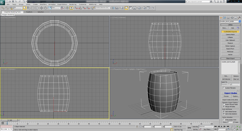
- As the pivot of the object in 3ds Max will be the pivot of the object in the engine, align the pivot to the origin. This will make placing the object easier once it's in Sandbox.
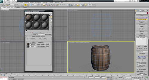
- Next, let's assign a material to our object. You can use the material we created in the previous recipe or create a new multi/sub-object material with two submaterials and name it
wooden_prop. - To assign the
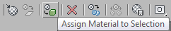
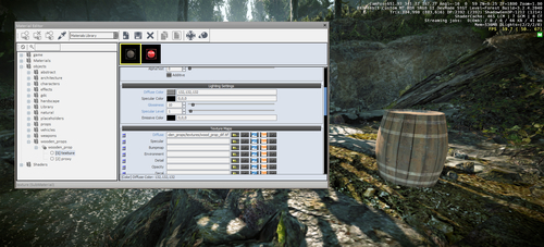
wooden_propmaterial to thewooden_barrel_simpleobject, select the object and open the material editor. - Next, click on the Assign Material to Selection icon.
Now that we have our material applied, we can assign a texture.
- Before assigning textures to our mesh, we must first make sure we have UV-mapped our object and that it has smoothing groups assigned. It is typically easier to preview smoothing groups with no texture being displayed.
Note
During export, if smoothing groups are not found on the mesh, the exporter will generate them automatically, which can cause errors to appear on the mesh.
In this example, I created a simple cylindrical unwrap:
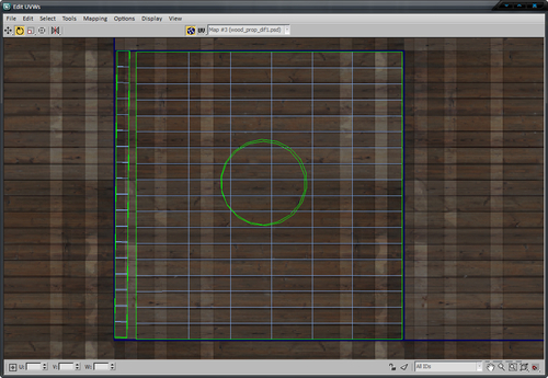
We can now assign a texture to the first submaterial. Ensure all the polygons in your object are set to material ID 1.
- Assign an appropriate wooden-type texture to the material.
- Finally, before exporting, it is important that your mesh be an editable poly or editable mesh and the modifier stack should be collapsed to avoid any unsupported modifiers on export.
- Save your .MAX scene at the same location as you want to store the asset. In this case, save the .MAX scene to
Gameobjectswooden_propswooden_barrel_simple.max. - To export the object, open the 3ds exporter and locate the Object Export section at the top of the interface. Select your prop and click on the Add Selected button. You will notice its name is added to the export list.
- Next, select the type of file you'd like to export. In this case, it is a geometry or . CGF file.
- Next, click the Export Nodes button. This will export the object to the same folder as the 3ds Max file. By default, the exported object will be given the same name as the 3ds Max filename, in our case
wooden_barrel_simple.cgf.The final step of this process is to preview the asset in engine!
- Open up the CryENGINE Sandbox and load a level.
- On the rollup bar, select brush and browse to
wooden_props/wooden_barrel_simple.cgfand drag it into the level.You will see that the geometry is there but the texture is red and reads replace me.
This is simply telling us that our .MTL file does not have a valid texture in the diffuse slot.
- To rectify this, select the prop and open the Sandbox Material Editor.
- Click the get material from selected tool.
- Then, browse to the diffuse slot of your object and using the browse button locate the texture you want to use for the object.
To visualize objects in a world, CryEngine uses the concept of render nodes and render elements. Render nodes represent general objects in the 3D engine. Among other things, they are used to build a hierarchy for visibility, allowing physics interactions, and finally for rendering. For actual rendering, these nodes add themselves to the renderer passing an appropriate render element, which implements the actual drawing of the object in engine. These objects are all seen as Y+ facing forward in the CryENGINE.
You will definitely want to know more about optimizing the physics and collision of objects using a collision or proxy mesh. You can also learn about occlusion geometry and user-defined physics properties next.
The physics proxy is the geometry that is used for collision detection. It can be part of the visible geometry or linked to it as a separate node. Usually the physics proxy geometry is a simplified version of the render geometry but it is also possible to use the render geometry directly for physics. However, for performance reasons, the collision geometry should be kept as simple as possible since checking for intersections on complex geometry is very expensive, especially if it happens often. A physics proxy is set up in the DCC tool exclusively. The only setup needed in Sandbox is assigning the surface type.
A simple geometry object that represents the shape of the render geometry is created in the DCC tool. It must be named "$occlusion" and linked to the object to which it belongs. In our example, this is the wall piece. No special material setup is needed.
- Occlusion polygons will always be treated as double-sided in the engine. A simple single-sided plane in the DCC application might be a sufficient occluder for a solid wall.
- Occlusion geometry usually has to be rasterized on the CPU, which is a lot slower than drawing it on the GPU. So, keep the number of polygons of the occluder geometry as low as possible; for example, just use a single-sided plane for a complex wall.
It may be required that some objects have specific information or properties applied. This can be accomplished through using the User Defined Properties in 3ds Max. Select an object and on the Edit menu, click Object Properties to access the User Defined Properties of that object.
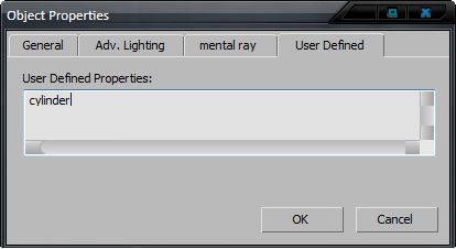
Some common parameters used are:
box— Force this proxy to be a Box primitive in the enginecylinder— Force this proxy to be a Cylinder primitive in the enginecapsule— Force this proxy to be a Capsule primitive in the enginesphere— Force this proxy to be a Sphere primitive in the engineMass = Value— defines the weight of an object mass = 0 sets the object to unmovable
- Having created and exported an object you can go to the Utilizing Geom entities instead of Brushes recipe in Chapter 3,Basic Level Layout
- Go to the next recipe in this chapter to learn how to create and export destroyable assets