C.8. Frequency Response of NPN – PNP Amplifier Due to the Base Shunt Capacitor
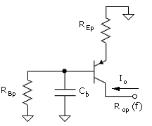
In the npn – pnp amplifier project, we determine VAFn directly through a gain measurement for a circuit configuration in which (C.51) is valid. The requirement that RBp ≈ 0 will be implemented by shunting the base of the pnp transistor to ground with a capacitor, Cb, as shown in Fig. C.12. The capacitor must be sufficiently large to hold the base at ground at the frequency of the gain measurements.
Figure C.12. Segment of the npn – pnp amplifier of Fig. C.10 showing the addition of a pnp base-bypass capacitor, Cb.

The expression to determine the required value of Cb can be obtained as follows: We start with the expression for Ro without Cb, which is (C.47) and repeated here (referring to the generalized circuit Fig. C.11):
![]()
With the capacitor in parallel with RBp, RB in (C.47) is replaced with the impedance of the parallel combination of RBp and Cb. The resulting Rop is frequency dependent and is given by
Equation C.56

This can be manipulated into the form
Equation C.57

where
Equation C.58
![]()
and
Equation C.59

The approximate form uses RBp >> rπp + REp. At f ≈ f1, Rop(f1) ≈ rop, such that a good approximation is obtained with dropping the “1” in the numerator. The approximate form is then
Equation C.60

Further rearranging leads to
Equation C.61
![]()
where
Equation C.62

and
Equation C.63

The approximate form again uses RBp >> rπp + REp.
Mathcad-generated plots of the magnitude of Rop(f) using (C.57) (and f2 and fz exact) and (C.61) (with the approximate forms for f2 and fz) are shown in Fig. C.13. These are for VAFp = 150 V, βacp = 50, RBp = 330 KΩ, REp = 800 Ω, Cb = 2 μF and IC = 1 mA. Characteristic frequencies are fz = 1.9 Hz and f2 = 38.2 Hz. The approximate form is very close to the exact form except in the lowest frequency range. For f → 0, Rop(f) ≈ rop in both cases. For example, in the exact and approximate cases, Rop(f) = 1.12rop and Rop(f) = 1.05rop, respectively, for f = 0.
Figure C.13. Mathcad-generated plots of the magnitude of Rop(f) using (57) and (61). The calculation made with the approximate form, (61), also uses the approximate forms for f2 and fz.

Substituting Rop(f) for Rop in (C.52), we obtain the frequency-dependent amplifier-circuit gain
Equation C.64

Then using (C.61) for Rop(f) in (C.64) results in
Equation C.65
![]()
where
Equation C.66
![]()
The approximate form uses Ropmax >> ron and the approximate f2 and fz.
The design frequency f3dB is obtained from ![]() [(6.8)]. Utilizing the approximate forms of f2, fz, and fp, f3dB simplifies to
[(6.8)]. Utilizing the approximate forms of f2, fz, and fp, f3dB simplifies to
Equation C.67

The result is significantly lower than f2 in (C.61) because Rop(f) is in parallel with ron, which is much smaller than the high-frequency value of Rop(f). The parameter βacp appears from the association βacp = gmrπp [(C.15)].
Mathcad-generated plots of (C.65) for the exact and approximate values for fp and fz are shown in Fig. C.14. The parameter and component values are from the plots of Fig. C.13 with the addition of VAFn = 250 V, βacn = βacp = 50, and RBn = RBp = 330 kΩ. With capacitor Cb = 2 μF, f3dB = 3.8 H (exact fp and fz) and f3dBapprox = 4.5 Hz [(C.67)].
Figure C.14. Plots of (C.65) with approximate and exact values for fz, (C.63), and fp, (C.66). The approximate form is sufficiently close for selecting Cb.

