B.4. Diode-Connected Transistor Circuits for Measuring Base and Collector Current
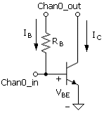
The circuit shown in Fig. B.9 is used in the parameter-determination project for measuring the base current with the collector open. The collector is tied to the output channel voltage, which holds the collector – base junction in reverse bias, and therefore in the active mode. The configuration is effectively a diode (open collector) with two terminals, base and emitter, and the diode current is the base current. The base current is that of the active-mode transistor, because the collector – base junction is maintained in a reverse-bias state. Note that according to (B.12), base-current magnitude does not otherwise depend on the value of the base – collector voltage. This is shown to be valid in the project. (The base current is much different when the collector terminal is tied to ground and the base – collector junction is forward biased.)
Figure B.9. Circuit for measuring base current in the open-collector diode-connected circuit.

The measurement circuit includes a current sensing resistor, RB. The relation between IB and VBE for this terminal configuration is (B.12), repeated here

As noted above, the base current of (B.12) exhibits no base-collector voltage dependence other than the requirement that the transistor be in the active mode.
This is assured in this circuit since VBC is
Equation B.15
![]()
where VCC ≡ Chan0_out.
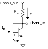
In the alternative diode circuit of Fig. B.10, the base and collector are connected such that VBC = 0 and the equation for the collector current is (B.7) with VBC = 0, or, simply,
Equation B.16
![]()
Figure B.10. Circuit for measuring emitter current. In this circuit, VBC = 0 and (B.16) applies.

The measured current in the circuit, that is, sensed by the sensing resistor, RE, is the emitter current, IE. This is the sum of (B.12) and (B.16), which is
Equation B.17

We note that (B.12) remains valid for VBC = 0. Current measurements from the two diode circuits provide, therefore, IC, from IC = IE –IB. In the parameter measurement project, it is verified that the base current is the same for both measurement circuits. This is a means by which the independence of base current on reverse voltage is demonstrated.
In the BJT parameter determination project, parameter extraction from the exponential relations is obtained from plots of current – voltage characteristics. The form of the log of the current versus voltage provides information on the two parameters of the exponential from a straight-line curve fit. For example combining the currents from the two circuits gives, as noted, IC = IE – IB and [from (B.16)]
Equation B.18
![]()
The zero voltage intercept thus reveals IS and the slope will show that nF ≈ 1.
A simple exponential represents the base current only approximately, as it is a combination of two exponentials; that is,
Equation B.19
![]()
In the measurement of the base current, using the circuit of Fig. B.9, the measured semilog plot will appear to be a straight line. This would suggest that the current – voltage relation is a simple exponential, as in the case of the collector current. However, parameters nEprime and ISEprime vary, depending on the given narrow range of base – emitter voltage of the measurement. Note that since nF = 1 and nE > 1, nEprime will be in the range 1 < nEprime < nE.
Sample measured results are shown in Fig. B.11, where the current is plotted on a log scale. For this plot, IC has been obtained from IC = IE – IB. Both plots are straight lines, indicating the exponential relationship between current and voltage for the two cases. Careful scrutiny of the lower curve (IB) should show a slight upward curvature since it is a mixture of two exponential terms, as noted. The steeper slope for emitter current is a result of the fact that nF = 1 and nEprime > 1.
Figure B.11. LabVIEW plot of measured currents (mA) versus base – emitter voltage (V). The ratio of the two is the βDC of the transistor.

