- Copyright
- National Improvements | Virtual Instrumentation Series
- Preface
- References
- Hardware and Software Requirements
- LabVIEW VI Libraries and Project and Problem Folders and Files
- Elementary Circuit Analysis for Analog Electronics
- Transistors and Voltage Amplification
- Characterization of MOS Transistors for Circuit Simulation
- Signal Conductance Parameters for Circuit Simulation
- Common-Source Amplifier Stage
- Coupling and Bypass Capacitors and Frequency Response
- MOSFET Source-Follower Buffer Stage
- MOSFET Differential Amplifier Stage
- DC (Bias) Circuit
- DC Imbalances
- Signal Voltage Gain of the Ideal Differential Amplifier Stage
- Effect of the Bias Resistor on Voltage Gain
- Differential Voltage Gain
- Common-Mode Voltage Gain
- Voltage Gains Including Transistor Output Resistance
- Body Effect and Voltage Gain
- Amplifier Gain with Differential and Common-Mode Inputs
- Comparison of Numerical Gain Results
- Summary of Equations
- Exercises and Projects
- MOSFET Current Sources
- Common-Source Amplifier with Current-Source Load
- Operational Amplifiers with Resistor Negative Feedback
- Operational Amplifier Applications with Capacitors
- Cascaded Amplifier Stages
- Combining NMOS and PMOS Circuits in Cascade
- Amplifier Gain of Differential Amplifier and Common-Source Stage in Cascade
- Stabilization of Signal Gain and Bias Current with a Source Resistor
- Common-Source Stage as a Series – Series Feedback Circuit
- Shunt – Series Cascade Amplifier
- Summary of Equations
- Development of a Basic CMOS Operational Amplifier
- Current-Source Bias for the Differential Amplifier Stage
- Current-Source Output Resistance and Common-Mode Gain
- Current-Source Load for the Common-Source Stage
- Current-Source Load for the Differential Stage
- Two-Stage Amplifier with Current-Source Biasing
- Output Buffer Stage
- Output Resistance of the Feedback Amplifier and Effect on Gain from Loading
- Output Circuit of the TS271 Opamp
- Summary of Equations
- Communicating with the Circuit Board: LabVIEW Programming and Measurement Exercises
- Characterization of the Bipolar Junction Transistor for Circuit Simulation
- Fundamentals of Bipolar Junction Transistor Action
- Base-Width Dependence on Junction Voltage
- BJT Base, Emitter, and Collector Currents in the Active Mode
- Diode-Connected Transistor Circuits for Measuring Base and Collector Current
- Output Characteristics of BJT in the Common-Emitter Mode
- SPICE Solution for IC versus VCE of the Measurement Circuit
- Collector-Emitter Voltage and Collector Current in the Saturation Region
- SPICE BJT βDC as a Function of Collector Current
- Signal or Incremental Common-Emitter Current Gain
- Summary of Equations
- Exercises and Projects
- Common-Emitter Amplifier Stage
- DC (Bias) Analysis
- Linear or Signal Model for the BJT
- Amplifier Voltage Gain
- Accuracy of Transistor Gain Measurements
- Effect of Finite Slope of the Transistor Output Characteristic
- Selection of Coupling Capacitors
- Common-Emitter Amplifier with Active Load
- Frequency Response of NPN – PNP Amplifier Due to the Base Shunt Capacitor
- Common-Emitter Stage with Emitter Resistor and the Emitter-Follower Amplifier Stage
- Summary of BJT Model Parameter Relations
- Summary of Circuit Equations
- Exercises and Projects
- Basic Circuit Analysis for Electronic Circuits and Programming Exercises
- Basic NMOS Common-Source Amplifier with Programming Exercises
- Characterization of the PMOS Transistor for Circuit Simulation
- Characterization of the NMOS Transistor for Circuit Simulation
- PMOS Common-Source Amplifier
- PMOS Common-Source Amplifier Stage with Current-Source Biasing
- NMOS Common-Source Amplifier Stage with Source-Resistor Bias
- NMOS Source-Follower Stage
- MOSFET Differential Amplifier Stage
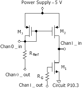
- Current Mirror and Common-Source Amplifier with Current-Source Load
- Operational Amplifier with Resistor Feedback
- Operational Amplifier Integrator and Oscillator
- Communicating with the Circuit Board Using the DAQ
- Sending and Receiving Voltages with the Sending and Receiving VIs
- Sending and Receiving Voltages from the Front Panel
- Plotting Measured Samples
- Using the Autoranging Voltmeter
- Observing the Oscilloscope Output Graph
- Discrete Output Voltage from the DAQ
- Discrete Input Voltage from the Circuit Board
- Using the Simultaneous Sending/Receiving Function
- Characterization of the Bipolar Junction Transistor for Circuit Simulation
- NPN Common-Emitter Amplifier
- NPN – PNP Common-Emitter Amplifier with Current-Source Load
P10.4. Evaluation of the Bias Setup
-
No Comment
..................Content has been hidden....................
You can't read the all page of ebook, please click here login for view all page.


