Gain.vi runs DC.vi to set up the bias and balance the circuit. It then sends out a signal squarewave and reads the response at the two outputs. Gain is calculated as output voltage divided by Vs/2. The 1/2 accounts for the voltage divider of the two gate resistors.
Set in Chan0_out (VDD), which you selected above in Parameters.vi. Run Gain.vi to obtain the gain at the two outputs. Adjust Vs for an output voltage magnitude similar to that in the example.
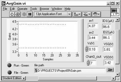
Now run AvgGain.vi with your VDD (Chan0_out) and Vs from Gain.vi. as a subVI repeatedly and averages the gains continuously during the measurements. With the Run Mode on (Green), allow the VI to continue to run until the average gain no longer appears to be changing. Reset Run Mode to halt execution.
Repeat with the File Mode button set to on (Green). The data file contains ID1, ID2, VSG VSD, av1, and av2. The Mathcad evaluation file will read these data.
Use SimAvgGain.vi to obtain the data file from the data saved in AvgGain.vi. Paste graph data and copy and paste the Digital Control values. Gains will be obtained from the graph data and need not be copied from the Digital Indicators.