SPICE IC versus VCE. This is performed with subVI SPICE.vi.
Straight-line curve fit from active-region data:
ICo ≡ IC(VCE = 0) (active-region extrapolation)
VAF = Slope/ICo
Procedure
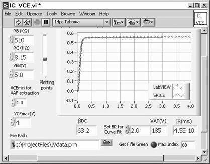
Open subVI, IC_VCEsub.vi. This VI will send out a value of VBB and sweeps VCC to sweep VCE. The maximum VCE is set for 4 V. Set the value of the resistors. Run and re-run while setting VBB for an active-region collector current of about 0.5 mA. Note that at this collector current, a maximum VCE of 4 V should be attainable as the circuit was designed (PB.3, PB.4) for ICmax ≈ 1 mA for VRc ≈ 9V. Default and save.
Now open VI, IC_VCE.vi. Set the value of the resistors. Set VBB from the subVI, IC_VCEsub.vi. Set VCEmax at 1 V. Run the VI and adjust BR for a best fit. Then re-run the VI with VCEmax set at 4 V to obtain a good value for VAF. VAF is computed from data points in the range 1 < VCE <VCEmax. Default and save the Front Panel. Double check to be sure that the subVI is defaulted and saved. The data are used in the output characteristic measurement simulation.