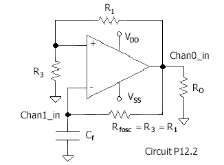
Note that Tosc is about ½ of the design Tmax from the integrator or about 50 ms.
Procedure
Turn off the power supply to reconnect the circuit into the oscillator configuration. Note the connection of Chan1_in, which measures the capacitor voltage.
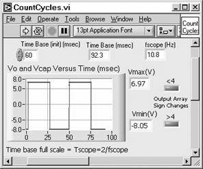
The main VI, Oscillator.vi(below), contains subVI’s CountCycles.vi and T.vi.CountCycles.vi determines the number of cycles in the oscillator output data array (Chan0_in) by checking for sign changes. It then increases or decreases the sample rate (for a fixed number of samples) until the number of sign changes in the array is 4. T.vi then checks the number of samples in the positive and negative pulses and multiplies the total by the sample rate to obtain the oscillator frequency. This frequency is used to set the time base of the oscilloscope, OscOscill.vi, to display five cycles of the oscillator waveform in the Front Panel of the main VI.
Connect the circuit with the power supply off to avoid damage to the chip. Then turn on the power supply. Open the oscillator oscilloscope VI, OscOscill.vi. Set the oscilloscope frequency, fscope, to the expected frequency of the oscillator (e.g., about 50 Hz). This sets up the scope for a full sweep of 2/fscope = 40 msec (Note that the scope is set for 2048 samples per sweep. Thus the resolution is 2/(2048fscope) = 19 μs for this example.)
Run OscOscill.vi to verify that the circuit is oscillating. Reset fscope for a time base that includes about two cycles of oscillation and rerun. Note that this fscope setting is approximately the frequency of the oscillator.
Open subVI CountCycles.vi. Set TimeBase (init)(msec) (full sweep time of scope) to include about two cycles of the oscillator waveform. (Use Time Base = 2/fscope.) Run the subVI to verify that the VI can find the final time base, which includes about two cycles.
Open Oscillator.vi. Set Time Base(init)(msec) to the value obtained in CountCycles.vi. Set in the value of Rfosc. Run the VI to obtain a final plot of the oscillator waveform and the frequency and period of the oscillator. Note the value found for the capacitor. Compare this with the value expected. The precision of the value depends on the precision of the Rfosc. Note that if the Time Base(init) is not set close to the final value, the VI will find the correct value, after some searching. Set the value of R3 for the record. It plays no role in the VI. Save the information in the Front Panel by obtaining a log.
Replace Rfosc with Rfosc ≈ 10 Rfosc(very approximately). Set in the new value in Oscillator.vi. Use Oscillator.vi to measure the new oscillator frequency. Compare the capacitor measurement. Obtain a log for this case.
Now replace R3 with R3 ≈ R3/10 (very approximately). Set in the new value of R3 for the log record. Run the VI. Note that the capacitor measurement is not valid for this case. The capacitor now charges to about 10% of the maximum output voltages before switching. This increases the frequency of oscillation, due to the shorter transient time. Obtain a log and save.