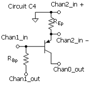
Circuit C4 is for obtaining the relevant SPICE parameters for the pnp. Of interest are VAFp, βDCp, and ISp. To obtain the parameters, connect Circuit C4 using the resistors calculated for this part (pnp). These will also be used in the complete amplifier. The VI for obtaining the parameters is IC_VEC.vi.
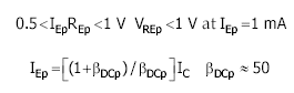
Open IC_VEC.vi. Install, in their Digital Indicators, RBp and REp. Run the VI IC_VEC.vi with subVI IC_VECsub.vi open to observe the plot in progress. Reset VBB as necessary to obtain an active-region IC of about 1 mA. Verify that IC = 1 mA with |VBB|<10 V can be obtained. |VBB| should be roughly 10 V at IC = 1 mA for maximum measurement precision. Adjust parameter βR for a curve fit using VCEmax = 1 V. Note that VCEmin is automatically set to 0.5 V for small VCEmax.
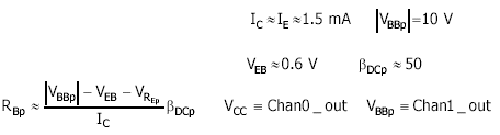
Determine the value of VAF specifically for the range that includes the bias value of VCE for the amplifier, which is VCE ≈ 5 V. Set VCEmin = 4 V and VCEmax = 6 V. Run the VI to obtain VAF. Compare the result with VCEmin = 3 V and VCEmax = 7 V. Note that in both cases the range brackets the operating point VCE = 5 V. Default and save the Front Panel to preserve the parameter values.
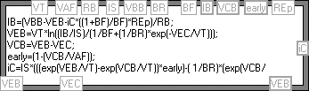
The computational subVI, SPICE_IV_Rep.vi, computes the SPICE plot, which is plotted along with the measured data. The Formula Node from the Diagram of SPICE_IV_REp.vi is shown below. A solution for IC as a function of VEC using the circuit and device equations is obtained. This is also explored in the project Mathcad file.