P10.5. Measurement of the Amplifier Gain versus Drain Current
Procedure
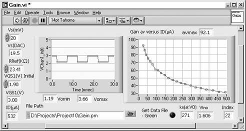
In Gain.vi, set VGS1 Initial to the value from the evaluation of SetVoID.vi above. The VI will sweep VGS1 over a range to include a maximum response of about 500 μA, according to the design above. Due to the high gain, the input signal voltage will be small in terms of the DAC. A subVI computes the actual output signal voltage from the value requested. The value computed is used in the gain computation.
Open SetVoID.vi along with Gain.vi. Set all numbers in the Digital Controls of Gain.vi. Run the VI and adjust Vs such that Vo min and Vo max are confined between 1 and 4 V, as in the example. These are indicated for the initial bias current (highest gain). Also, adjust (down) the Control-Loop Constant of SetVoID.vi if the bias setting function oscillates out of control. Save the Front Panel when the VI is functioning properly.
Open AvgGain_ID.vi. This VI runs Gain.vi as a subVI repeatedly and averages the plots of each execution. Set the Run Mode switch to Continuous and the File Mode switch to on (Green) and run the VI for data smoothing. Switch to One Plot to halt the execution. The data file includes gain, VGS1, and ID. This is used in the project Mathcad analysis file.
Obtain a data file from saved data in AvgGain_ID.vi with SimAvgGain_ID.vi.