Connect Circuit B3 and run subVI, IterVCC.vi. The VI adjusts VCC to set VCE = VBE. Try various values of VBB at VCCinit = 1 V. Verify that the VI can adjust VCC to make VBE = VCE (VCB = 0). With a proper choice of resistors, as verified in PB.3, VCC ≈ 10V for VBB ≈ 10V. Beta_IC.vi sweeps VBB until ICmax ≈ 1mA (very approximately) or Chan0_out = 10 V.
Open Beta_IC.vi. Set values for RC and RB in the Digital Controls. Run the VI and re-run while resetting VBBinit to obtain an initial value of IC of about 0.01 mA. This should match the lowest current in the measurement of the emitter current of Circuit B1. Note that if VCC or VBB attempts to become greater than 10 V, the VI will halt with IC < 1 mA. A red VBB or VCC button will indicate this condition. If the maximum current in the plot is near this value, this is sufficient. Default and save the Front Panel. Note that for the case of VCC > 10 V for the last measured current, the last (invalid) data point set will be eliminated from the Mathcad data file.
Obtain a data file of the graph. Set Get File Green (logic 1) to green and write the file path and file name. Run the VI to obtain the data file. The data file is used in ProjectB2.mcd.
For obtaining a data set at a later time, such as for simulation only, open Beta_IC.vi; retrieve the data log from the Front Panel. Then go to the Diagram of Beta_IC.vi and open XYtoDataFile2.vi (or use Browse>>Show VI Hierarchy). Copy and paste data and run the data file VI to obtain the file.
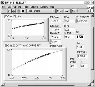
Open BF_NE_ISE.vi (below). Install your plot data and value of IS from Beta_IC.vi into the Control Graph and Digital Indicator, respectively. Run the VI to obtain IS, NE, and ISE. The VI performs a curve fit using (B.38). Three data-point sets used by the VI are nearest to 0.01, 0.1 and 1 mA.
The VI, CompareBetas.vi (below), is for comparing the results from the two measurements from PB.3 and PB.4. Open the VI and paste data from Beta.vi and Beta_IC.vi in the two Control Graphs. Run the VI to compare the plots. The results are expected to be very similar. This is experimental proof of the fact that IB is independent of VBC, unlike the collector current. Note that VBC = 0 V in the measurement with Beta_IC.vi, but that VCB = IBRB in the base current measurement of Diode_IV.vi. The latter is as high as about 9 V.