With our camera driver running, we can use the calibration tool of ROS to calibrate it. It is important that the camera driver provides CameraInfo messages and has the camera_info_set service, which allows you to set the path to the calibration results file. Later, this calibration information is loaded by the image pipeline when using the camera. One camera driver that satisfies these prerequisites is the camera1394 driver for the FireWire cameras. In order to calibrate your FireWire camera, use the following command:
$ roslaunch chapter5_tutorialscalibration_firewire_camera_ chessboard.launch
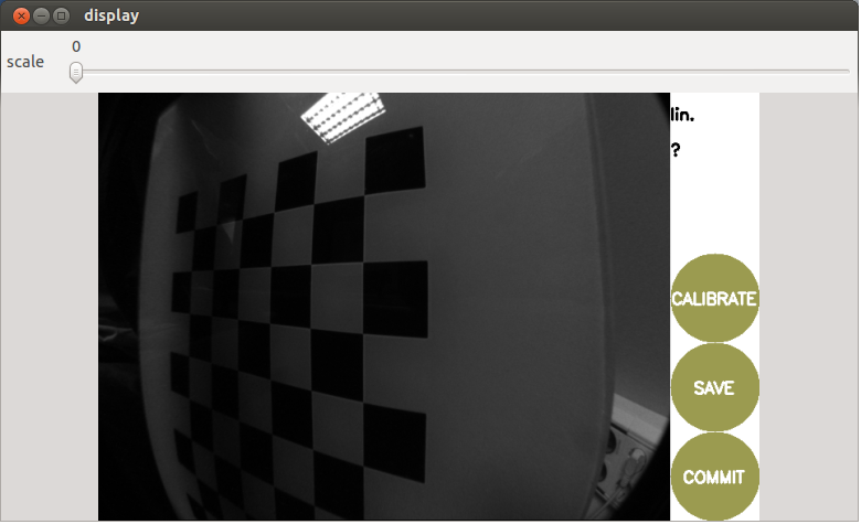
This will open a GUI that automatically selects the views of our calibration pattern and provides bars to inform users how each axis is covered by the views retrieved. It comprises the x and y axes, meaning how close the pattern has been shown to each extreme of these axes in the image plane, that is, the horizontal and vertical axes, respectively. Then, the scale goes from close to far (up to the distance at which the detection works). Finally, skew requires that views of the pattern tilt in both the x and y axes. The following three buttons these bars are disabled by default, as shown in the following screenshot:
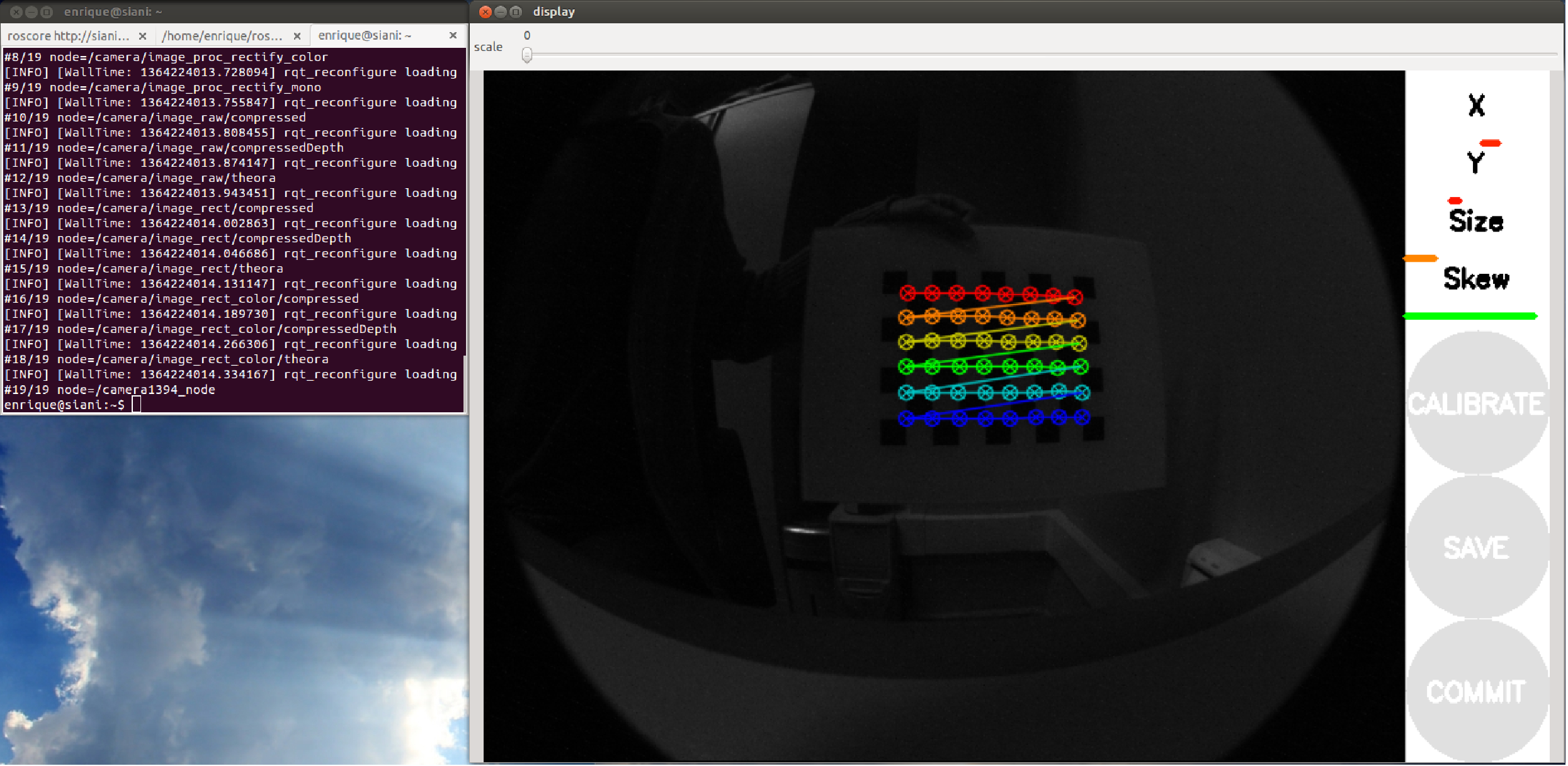
You will see the points detected overlaid over the pattern every time the detector finds them. The views are automatically selected to cover a representative number of different views, so you must show views to make the bars become green from one side to the other, following the instructions given in the following section. In theory, two views are enough, but in practice around ten are usually needed. In fact, this interface captures even more (30 to 40). You should avoid fast movements because blurry images are bad for detection. Once the tool has enough views, it will allow you to calibrate, that is, to start the optimizer which, given the points detected in the calibration pattern views, solves the system of the pinhole camera model.
This is shown in the following screenshot:
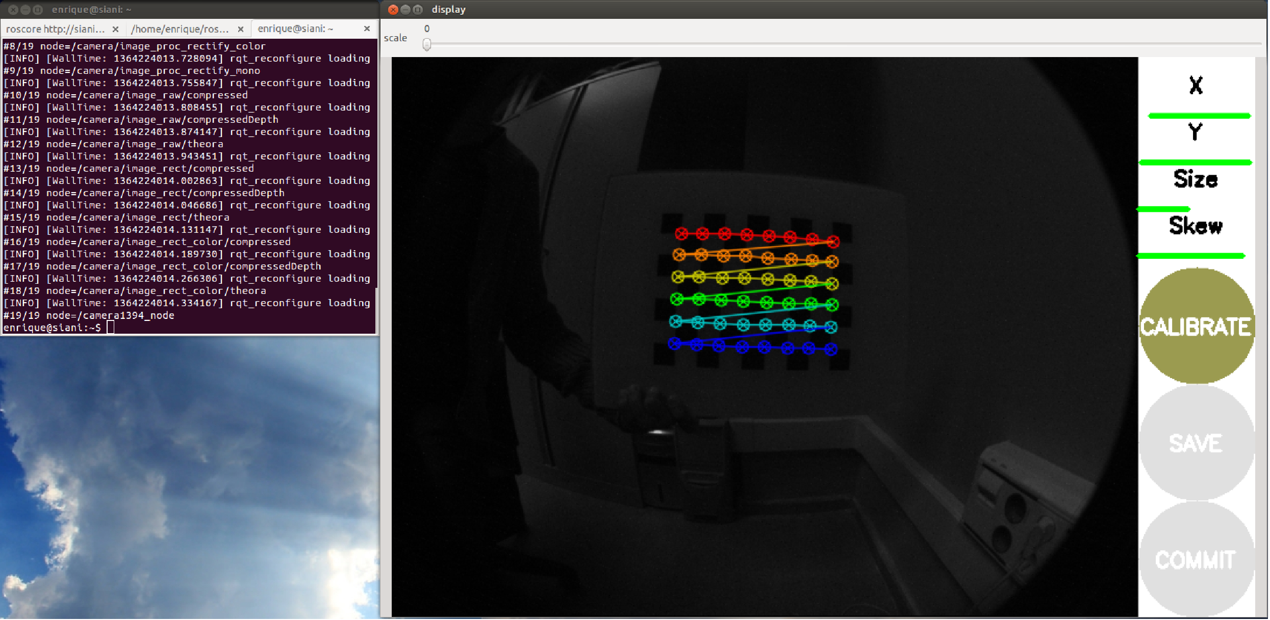
Then, you can save the calibration data and commit the calibration results to the camera, that is, it uses the camera_info_set service to commit the calibration to the camera, so later it is detected automatically by the ROS image pipeline.
The launch file provided for the calibration simply uses cameracalibrator.py of the camera_calibration package:
<node pkg="camera_calibration" type="cameracalibrator.py"
name="cameracalibrator" args="--size 8x6 --square 0.030"
output="screen">
  <remap from="image" to="camera/image_colour" />
  <remap from="camera" to="camera" />
</node>
The calibration tool only needs the pattern's characteristics (the number of squares and their size, --size 8x6 and --square 0.030 in this case), the image topic, and the camera namespace.
The launch file also runs the image pipeline, but it is not required. In fact, instead of the image_color topic, we could have used the image_raw one.
Once you have saved the calibration (Save button), a file is created in your /tmp directory. It contains the calibration pattern views used for the calibration. You can find it at /tmp/calibrationdata.tar.gz; the ones used for calibration in the section can be found in the calibration directory and the firewire_camera subfolder for the FireWire camera. Similarly, on the terminal (stdout output), you will see information regarding the views taken and the calibration results. The ones obtained for the section are in the same folder as the calibration data. The calibration results can also be consulted in the ost.txt file inside the calibrationdata.tar.gz ZIP file. Remember that after the commit, the calibration file is updated with the calibration matrix and the coefficients of the distortion model. A good way to do so consists of creating a dummy calibration file before the calibration. In our package, that file is in calibration/firewire_camera/calibration_firewire_camera.yaml, which is referenced by the parameters file:
camera_info_url:
 package://chapter5_tutorials/calibration/firewire_camera/calibrati
 on_firewire_camera.yaml
Now, we can use our camera again with the image pipeline, and the rectified images will have the distortion corrected as a clear sign that the camera is calibrated correctly. Since ROS uses the Zhang calibration method implemented in OpenCV, our advice is that you consult its documentation at http://docs.opencv.org/doc/tutorials/calib3d/camera_calibration/camera_calibration.html.
Finally, you can also play with different calibration patterns using the following launch files for circles and asymmetric circles (https://raw.githubusercontent.com/opencv/opencv/05b15943d6a42c99e5f921b7dbaa8323f3c042c6/doc/acircles_pattern.png), prepared for FireWire cameras, as an example:
roslaunchchapter5_tutorialscalibration_firewire_camera_circles.lau
 nchroslaunchchapter5_tutorialscalibration_firewire_camera_acircles.la
 unch
You can also use multiple chessboard patterns for a single calibration using patterns of different sizes. However, we think it is enough to use a single chessboard pattern printed with good quality. Indeed, for the USB camera driver, we only use that.
In the case of the USB camera driver, we have a more powerful launch file that integrates the camera calibration node; there is also a standalone one for FireWire cameras. In order to calibrate your camera, use the following action:
$ roslaunch chapter5_tutorials camera.launch calibrate:=true
In the following screenshots, you will see the steps of the calibration process in the GUI, identical to the case of FireWire cameras. That means we have an operating camera_info_set service:

After pressing the CALIBRATE button, the calibration optimization algorithm will take a while to find the best intrinsic and extrinsic parameters. Once it is done, SAVE and COMMIT will be enabled. The following screenshot shows this: