A differential wheeled robot will have two wheels connected on opposite sides of the robot chassis which is supported by one or two caster wheels. The wheels will control the speed of the robot by adjusting individual velocity. If the two motors are running at the same speed it will move forward or backward. If a wheel is running slower than the other, the robot will turn to the side of the lower speed. If we want to turn the robot to the left side, reduce the velocity of the left wheel compared to the right and vice versa.
There are two supporting wheels called caster wheels that will support the robot and freely rotate according to the movement of the main wheels.
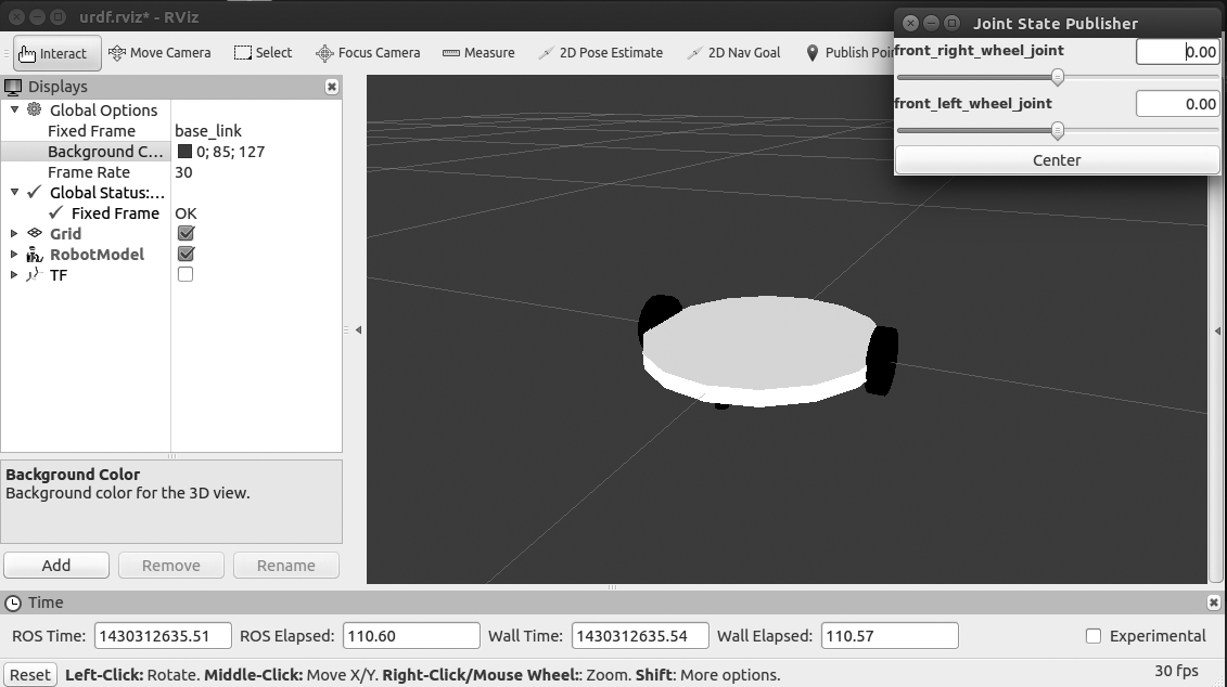
The UDRF model of this robot is present in the cloned ROS package. The final robot model is shown as follows:

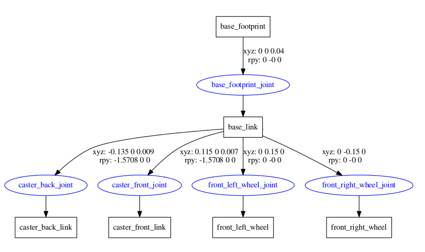
The preceding robot has five joints and five links. The two main joints are two
wheel joints and the other three joints are two fixed joints by caster wheels, and one fixed joint by base foot print to the base link of the robot.
Here is the connection graph of this robot:
We can go through the important section of code in the UDRF file. The UDRF file name called diff_wheeled_robot.xacro is placed inside the urdf folder of the cloned ROS package.
The first section of the UDRF file is given here. The robot is named as differential_wheeled_robot and it also includes a UDRF file called wheel.urdf.xacro. This xacro file contains the definition of the wheel and its transmission; if we use this xacro file, then we can avoid writing two definitions for the two wheels.
We use this xacro definition because two wheels are identical in shape and size:
<?xml version="1.0"?>
<robot name="differential_wheeled_robot" xmlns:xacro="http://www.ros.org/wiki/xacro">

  <xacro:include filename="$(find mastering_ros_robot_description_pkg)/urdf/wheel.urdf.xacro" />
The definition of a wheel inside wheel.urdf.xacro is given here. We can mention whether the wheel has to be placed to the left, right, front, or back. Using this macro, we can create a maximum of four wheels, but now we require only two:
<xacro:macro name="wheel" params="fb lr parent translateX translateY flipY"> <!--fb : front, back ; lr: left, right -->
    <link name="${fb}_${lr}_wheel">
We also mention the Gazebo parameters required for simulation. Mentioned here are the Gazebo parameters associated with a wheel. We can mention the frictional coefficient and stiffness co-efficient using the gazeboreference tag:
    <gazebo reference="${fb}_${lr}_wheel">
      <mu1 value="1.0"/>
      <mu2 value="1.0"/>
      <kp  value="10000000.0" />
      <kd  value="1.0" />
      <fdir1 value="1 0 0"/>
      <material>Gazebo/Grey</material>
      <turnGravityOff>false</turnGravityOff>
    </gazebo>
The joints that we define for a wheel are continuous joints because there is no limit
in the wheel joint. The parent link here is the robot base and the child link is each wheel:
    <joint name="${fb}_${lr}_wheel_joint" type="continuous">
      <parent link="${parent}"/>
      <child link="${fb}_${lr}_wheel"/>
      <origin xyz="${translateX *
We also need to mention the transmission tag of each wheel; the macro of the wheel is as follows:
    <!-- Transmission is important to link the joints and the controller -->
    <transmission name="${fb}_${lr}_wheel_joint_trans">
      <type>transmission_interface/SimpleTransmission</type>
      <joint name="${fb}_${lr}_wheel_joint" />
      <actuator name="${fb}_${lr}_wheel_joint_motor">
        <hardwareInterface>EffortJointInterface</hardwareInterface>
        <mechanicalReduction>1</mechanicalReduction>
      </actuator>
    </transmission>

  </xacro:macro>
</robot>
In diff_wheeled_robot.xacro, we can use the following lines to use the macros defined inside wheel.urdf.xacro:
  <wheel fb="front" lr="right" parent="base_link" translateX="0" translateY="-0.5" flipY="-1"/>
  <wheel fb="front" lr="left" parent="base_link" translateX="0" translateY="0.5" flipY="-1"/>
Using the preceding lines, we define the wheels on the left and right of the robot base. The robot base is cylindrical in shape as shown in the preceding figure. The inertia calculating macro is given here. This xacro snippet will use the mass, radius, and height of the cylinder and calculate inertia using this equation:
  <!-- Macro for calculating inertia of cylinder -->
  <macro name="cylinder_inertia" params="m r h">
    <inertia  ixx="${m*(3*r*r+h*h)/12}" ixy = "0" ixz = "0"
              iyy="${m*(3*r*r+h*h)/12}" iyz = "0"
              izz="${m*r*r/2}" />
  </macro>
The launch file definition for displaying this root model in RViz is given here.
The launch file is named view_mobile_robot.launch:
<launch>
  <arg name="model" />
  <!-- Parsing xacro and setting robot_description parameter -->
  <param name="robot_description" command="$(find xacro)/xacro.py $(find mastering_ros_robot_description_pkg)/urdf/diff_wheeled_robot.xacro" />
  <!-- Setting gui parameter to true for display joint slider -->
  <param name="use_gui" value="true"/>
  <!-- Starting Joint state publisher node which will publish the joint values -->
  <node name="joint_state_publisher" pkg="joint_state_publisher" type="joint_state_publisher" />
  <!-- Starting robot state publish which will publish tf -->
  <node name="robot_state_publisher" pkg="robot_state_publisher" type="state_publisher" />
  <!-- Launch visualization in rviz -->
  <node name="rviz" pkg="rviz" type="rviz" args="-d $(find mastering_ros_robot_description_pkg)/urdf.rviz" required="true" />
</launch>
The only difference between the arm UDRF file is the change in the name; the other sections are the same.
We can view the mobile robot using the following command:
    $ roslaunch mastering_ros_robot_description_pkg
 view_mobile_robot.launch
The screenshot of the robot in RViz is as follows: