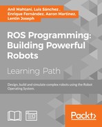
In this section, we will discuss a basic software block diagram of a self-driving car that was in DARPA Challenge:
Let's learn what each block means. Each block can interact with others using inter-process communication (IPC) or shared memory. ROS messaging middleware is a perfect fit in this scenario. In DARPA Challenge, they implemented a publish/subscribe mechanism to do these tasks. One of the IPC library development by MIT for 2006 DARPA challenge was Lightweight Communications and Marshalling (LCM). You may can learn more about LCM from the following link (https://lcm-proj.github.io/).
- Sensor interface modules: As the name of the module indicates, all the communication between the sensors and the vehicle is done in this block. The block enables us to provide the various kinds of sensor data to all other blocks. The main sensors include LIDAR, camera, radar, GPS, IMU, and wheel encoders.
- Perception modules: These modules perform processing on perception data from sensors such as LIDAR, camera, and radar and segment the data to find moving and static objects. They also help localize the self-driving car relative to the digital map of the environment.
- Navigation modules: This module determines the behavior of the autonomous car. It has motion planners and finite state machines for different behaviors in the robot.
- Vehicle interface: After the path planning, the control commands, such as steering, throttle, and brake control, are sent to the vehicle through a drive-by-wire (DBW) interface. DBW basically works through the CAN bus. Only some vehicles support the DBW interface. Examples are the Lincoln MKZ, VW Passat Wagon, and some models from Nissan.
- User interface: The user interface section provides controls to the user. It can be a touch screen to view maps and set the destination. Also, there is an emergency stop button for the user.
- Global services: This set of modules helps log the data and has time stamping and message-passing support to keep the software running reliably.
Simulating and interfacing self-driving car sensors in ROS
In the preceding section, we discussed the basic concepts of a self-driving car. That understanding will definitely help in this section too. In this section, we are simulating and interfacing some of the sensors that we are using in self-driving cars. Here is the list of sensors that we are going to simulate and interface with ROS:
- Velodyne LIDAR
- Laser scanner
- Camera
- Stereo camera
- GPS
- IMU
- Ultrasonic sensor
We'll discuss how to set up the simulation using ROS and Gazebo and read the sensor values. This sensor interfacing will be useful when you build your own self-driving car simulation from scratch. So if you know how to simulate and interface these sensors, it can definitely accelerate your self-driving car development.