Dagu encoders are composed of two parts for each wheel. A magnetic disk with eight poles: four north poles and four south poles and a Hall effect sensor. The magnet disk is placed in a shaft of a wheel and the Hall effect must face it at a maximum distance of 3 mm.

Once you have placed the encoder on the wheel, you can connect it to the Arduino. The Hall effect sensor is directly soldered to three wires: black, ground, and white.
The black wire is the ground of the sensor and must be connected to Arduino ground; the red one is for power supply and should be connected to 5V. The white wire is the signal; the signal is binary and changes his values from high level to low level once the magnet disk turns and a different pole faces the sensor.
So, it is logical to think in connecting signal wire to an Arduino digital pin. But furthermore, encoders' signals can change very quickly depending on the revolutions of the motor and the number of poles/steps of your encoder. It is recommended to connect encoder signals to Arduino interruption pins to achieve a faster reading of the signal changes
For Arduino/Genuino Uno, interruption pins are digital pin 2 and digital pin 3. We will connect the encoders to this pin. For checking how the encoder works and learning how you can use Arduino interruptions, we will use the following code:
#include <std_msgs/Float32.h>
#include <TimerOne.h>
#define LOOP_TIME 200000
#define left_encoder_pin 3
#define right_encoder_pin 2
We declare new variables to count each tick of the encoders and create topics in order to publish the wheel velocities:
unsigned int counter_left=0;
unsigned int counter_right = 0;

ros::NodeHandle nh;
std_msgs::Float32 left_wheel_vel;
ros::Publisher left_wheel_vel_pub("/left_wheel_velocity",
 &left_wheel_vel);

std_msgs::Float32 right_wheel_vel;
ros::Publisher right_wheel_vel_pub("/right_wheel_velocity",
 &right_wheel_vel);
We have to create two functions to handle encoders' interruptions. Each time a change is detected in the right or left encoder pin, a count is increased:
void docount_left() // counts from the speed sensor
{
  counter_left++; // increase +1 the counter value
}
void docount_right() // counts from the speed sensor
{
  counter_right++; // increase +1 the counter value
}
A timer is used to publish the velocity of each wheel. We use the encoder counters, the wheel radius and the timer duration to calculate speed:void timerIsr():
{
  Timer1.detachInterrupt(); //stop the timer
  //Left Motor Speed
  left_wheel_vel.data = counter_left;
  left_wheel_vel_pub.publish(&left_wheel_vel);
  right_wheel_vel.data = counter_right;
  right_wheel_vel_pub.publish(&right_wheel_vel);
  counter_right=0;
  counter_left=0;
  Timer1.attachInterrupt( timerIsr ); //enable the timer
}
Finally, in the setup functions, the encoder pins are declared as INPUT_PULLUP. This means that Arduino will treat them as inputs and it will connect internally a pull-up resistor to these pins:
//Setup for encoders
pinMode(right_encoder_pin, INPUT_PULLUP);
pinMode(left_encoder_pin, INPUT_PULLUP);
Timer1.initialize(LOOP_TIME);
attachInterrupt(digitalPinToInterrupt(left_encoder_pin),
 docount_left, CHANGE); // increase counter when speed sensor pin
 goes HighattachInterrupt(digitalPinToInterrupt(right_encoder_pin),
 docount_right, CHANGE); // increase counter when speed sensor pin
 goes High
Also, the messages that will be published have been advertised in the setup:
nh.advertise(left_wheel_vel_pub);
nh.advertise(right_wheel_vel_pub);
Timer1.attachInterrupt( timerIsr ); // enable the timer
You can upload now the code to the board, and run the Arduino node:
    $ roscore
    $ rosrun rosserial_python serial_node.py /dev/ttyACM0
When you type the following in another terminal:
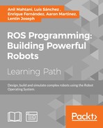
$ rostopic list
You will see:
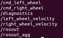
You can now make an echo of the topic and turn the wheels or you can run rqt_graph. Also, you can check the frequency of each publications with rostopic hz:
OK, now we can unify these two topics in geometry msgs::Twist as we have done with /cmd_vel previously. We have to create a new geometry_msgs::Twist to send the velocity of the platform and a topic publisher for this message:
geometry_msgs::Twist sensor_vel;
ros::Publisher sensor_vel_pub("/sensor_velocity", &sensor_vel);
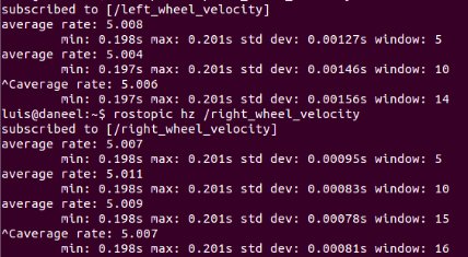
And in the timerISR() function, we calculate the linear and angular velocities using kinematics equations:
sensor_vel.linear.x = radius*(left_wheel_vel.data +
 right_wheel_vel.data)/2;
sensor_vel.linear.y = 0;
sensor_vel.linear.z = 0;
sensor_vel.angular.x = 0;
sensor_vel.angular.y = 0;
sensor_vel.angular.z = radius*(left_wheel_vel.data +
 right_wheel_vel.data)/L;
sensor_vel_pub.publish(&sensor_vel);
After that, we can modify the odometry node to subscribe to the real odometry data from our encoder sensors published in the topic /sensor_vel:
You can check the example with the following command:
    $ roslaunch chapter8_tutorials chapter8_robot_encoders.launch
    $ rosrun rosserial_python serial_node.py /dev/ttyACM0