
Following figure shows the base footprint of our robot:
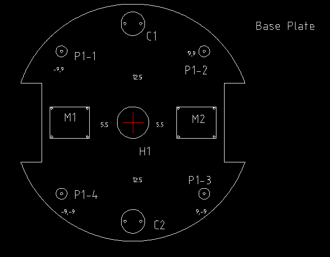
The preceding figure shows the base footprint of our robot. You can see that it is circular and there are two slots on the left and right for attaching motors and wheels. M1 and M2 are the positions of the motor body, and the shaft will be in the slots. The motors can be put on the top of the plate or on the bottom. Here, we are attaching the motors to the bottom of this plate. The wheels should be inside these two slots. We have to make sure that the slot length is greater than the wheel diameter. You can see C1 and C2, which are the positions where we are attaching the caster wheels. Caster wheels are freely rotating wheels without any actuation. We can select available caster wheels for this purpose. Some caster wheels may have issues moving on uneven terrain. In that case, we may need to use a caster wheel with spring suspension. This ensures that it always touches the ground even when the terrain is slightly uneven.
You can also see parts such as P1-1 and P1-4, which are the poles from the base plate. If we want to attach an additional layer above the base plate, we can use these poles as the pillars. Poles can be hard plastic or steel, which are fixed to the base plate and have a provision to attach a hollow tube on them. Each poles is screwed on to the base plate.
The center of the base plate is hollow; this will be useful when we have to take wires from the motors. Mainly, we will attach the electronic board required for the robot to this plate.
Here are the dimensions of base plate and each part:
| Parts of base plate | Dimensions (length x height) or (radius) in cm |
| M1 and M2 | 5 x 4 |
| C1 and C2 | Radius = 1.5 |
| S (screw) | 0.15 |
| P1-1, P1-2, P1-3, P1-4 | Outer radius 0.7, Height 3.5 |
| Left and right wheel section | 2.5 x 10 |
| Base plate | Radius = 15 |