In Arduino and other controller boards, what we have created a did was make a hardware ROS node. But RPi and Odroid are single-board computers, so we can run ROS on the board itself. We can run ROS on these two boards in three ways. We can run ROS on the same board, or we can run the ROS master on the board and connect other ROS nodes from the PC or make the PC the ROS master and make the board the client.
In this section, we are going to create a simple demo to blink an LED using ROS topics from the same board. To work with Raspberry Pi and Odroid, we have to use a library called wiringpi.
Here are the commands to install wiringpi on Raspberry Pi:
    $ git clone git clone git://git.drogon.net/wiringPi
    $ cd wiringPi
    $ sudo ./build
And these are the commands to install wiringpi on Odroid:
    $ git clone https://github.com/hardkernel/wiringPi.git
    $ cd wiringPi
    $ sudo ./build
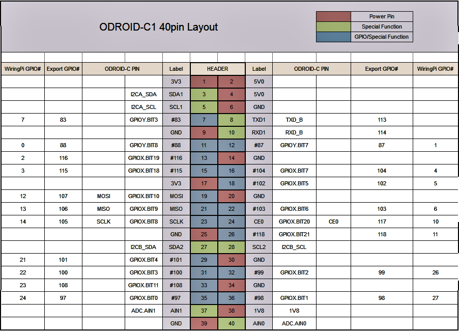
After installing wiringpi, we should know the GPIO pin layout of each board in order to program it. The GPIO pin layout of the boards is as follows:

The pin layout of Odroid is similar to RPi. Here is the GPIO pin layout of Odroid C1/C2: